
 ?Mathematical formulae have been encoded as MathML and are displayed in this HTML version using MathJax in order to improve their display. Uncheck the box to turn MathJax off. This feature requires Javascript. Click on a formula to zoom.
ABSTRACT
Indoor positioning with high accuracy plays an important role in different application scenarios. As a widely used mobile communication signal, the Long-Term Evolution (LTE) network can be well received in indoor and outdoor environments. This article studies a method of using different reference signals in the LTE downlink for carrier phase time of arrival (TOA) estimation. Specifically, a solution is proposed and a multipath tracking Software Defined Receiver (SDR) is developed for indoor positioning. With our SDR indoor positioning system, the pilot signals of the LTE signals are firstly obtained by the coarse synchronization and demodulation. Then, with the assistance of the pilot signals, the time delay acquisition, the multipath estimating delay lock loop (MEDLL) algorithm, and the multipath anomaly detection are sequentially carried out to obtain navigation observations of received signals. Furthermore, to compare the performance of different pilot signals, the Secondary Synchronous Signals (SSS) and Cell Reference Signals (CRS) are used as pilot signals for carrier phase-based TOA estimation, respectively. Finally, to quantify the accuracy of our multipath tracking SDR, indoor field tests are carried out in a conference environment, where an LTE base station is installed for commercial use. Our test results based on CRS show that, in the static test scenarios, the TOA accuracy measured by the 1-σ error interval is about 0.5 m, while in the mobile environment, the probability of range accuracy within 1.0 m is 95%.
1. Introduction
In recent years, with the development of the economy and emerging applications, research on indoor pedestrian navigation has been increasing (Chen and Chen Citation2017; Dangermond and Michael Citation2020). In complex indoor environments, wireless signals have much more severe multipath effects and signal attenuation. Indoor positioning faces difficulties and challenges that are different from traditional outdoor navigation (Li et al. Citation2020; Trinder and Liu Citation2020). As one of the most effective outdoor navigation methods, the Global Navigation Satellite System (GNSS) is difficult to cope with the severe attenuation and scattering of signals in indoor environments for navigation (Chen et al. Citation2015; Raquet and Martin Citation2008).
Long-Term Evolution (LTE) is a wireless communication technology standard developed by the 3rd Generation Partnership Project (3GPP) (E-UTRA Citation2019; Shamaei and Kassas Citation2018). The LTE is a type of cellular mobile network, and the coverage area of LTE cells varies from nanoscale base stations (BSs) with a radius of tens of meters to macrocell macrocellular BSs with a radius of 100 km (Lee et al. Citation2012). In the major cities and regions of China, the LTE network has been widely deployed. Especially for urban centers, to improve the quality of LTE networks, BSs are more densely distributed. So far, there have been 5.58 million LTE BSs in China, and more than 1.24 billion smartphone users use LTE networks every day (Yi Citation2019).
LTE technology has been of interest in urban and indoor positioning, owing to its worldwide usage, good coverage in urban areas, and desirable signal properties. Positioning techniques including Enhanced Cell ID (CID), Observed Time Difference of Arrival (OTDOA) with a dedicated Positioning Reference Signal (PRS), and Assisted-Global Navigation Satellite System (A-GNSS) have been specified in the LTE standardization process. In Cherian and Rudrapatna (Citation2013), these several positioning techniques based on LTE signals are described in detail. A new cluster-based LTE fingerprinting method is proposed by Mondal et al. (Citation2015) that uses CIDs to reduce the search space for cluster operations, thereby reducing computational complexity and localization time. In Del Peral-Rosado et al. (Citation2016), The Time of Arrival (TOA) measurements from the LTE network are fused with the pseudorange measurements from the GNSS system. The developed A-GNSS hybrid positioning system not only improves the original accuracy of the GNSS system but also provides location-based services in areas where GNSS is not available. Several signal receivers based on LTE signal Time Difference of Arrival (TDOA)/TOA are shown in Driusso et al. (Citation2017) and Shamaei and Kassas (Citation2018), which achieve reliable positioning accuracy in urban areas. In particular, Wang and Morton (Citation2020) consider the multipath effect of LTE signal propagation in urban environments, which improves the accuracy and stability of LTE signal TOA estimation. From the above, many researchers have shown that the LTE signal has a strong potential for navigation and positioning. However, most field experiments by researchers have been limited to urban outdoor environments. Given the severe multipath effects in indoor environments, there are currently few signal tracking and positioning methods that can be used in indoor environments.
Currently, as the Signal of Opportunity (SoP) for indoor positioning, the Wireless Local Area Network (WLAN) (Yan et al. Citation2021), the Bluetooth Low Energy (BLE) (Chen and Pei Citation2013), and the cellular network signal (Zhou et al. Citation2020; Chen et al. Citation2021; Liu et al. Citation2022b) have been widely used (Chen et al. Citation2011; Yan et al. Citation2018; Li et al. Citation2016). With the continuous improvement of LTE network construction, many LTE micro BSs have appeared in large shopping malls and crowded areas in the urban center. These LTE signals not only have a high Signal-to-Noise Ratio (SNR) but can also be used consistently by users over a long period of time under the maintenance of the mobile operator. As an SoP, the LTE signal shows extremely high potential and application value, whether it is used alone to develop an indoor positioning system or integrated with existing positioning systems.
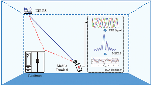
In this article, a multipath tracking Software Defined Receiver (SDR) based on an improved multipath estimating delay lock loop (MEDLL) algorithm as shown in , which is developed to obtain highly accurate TOA estimates from LTE signals for severe multipath effects in indoor environments . In the developed SDR, the multipath signals are efficiently extracted by the MEDLL algorithm and the first path signal is accurately tracked. Meanwhile, the LTE indoor micro-BS is used for continuous tracking experiments to verify the feasibility of LTE signals in indoor positioning. The conventional Delay Lock Loop (DLL) algorithm is used as a comparison method to verify the effectiveness of the developed SDR in this article. Specifically, the main contributions of this article are summarized as follows:
A multipath tracking SDR for carrier phase TOA estimation is developed. The MEDLL algorithm is applied to reduce the influence of the multipath effects in indoor environments on continuous time delay tracking. The DLL is also used as a comparison algorithm for indoor LTE signal delay tracking.
For the complex characteristics of indoor environments, a multipath anomaly detection process is added to the multipath tracking SDR. This reduces the number of iterations of the MEDLL algorithm and effectively improves the operational efficiency of the algorithm when path signals are anomalous.
The Secondary Synchronization Signal (SSS) and Cell Reference Signal (CRS) of the commercial LTE signal are used as pilot signals for TOA estimation, respectively. The carrier phase ranging estimation obtained from static experiment and mobile experiment TOA estimation are analyzed. The accuracy and stability of the developed SDR in different states are verified.
Figure 1. Schematic diagram of multipath tracking for TOA estimation with LTE signals in indoor environments.
The rest of this article is organized as follows: Section II briefly describes the pilot signals used for TOA estimation and the signal model of the LTE signal. Section III details coarse synchronization and demodulation, time delay acquisition, MEDLL algorithm, multipath anomaly detection, and carrier phase TOA estimation in multipath tracking SDR. Section IV describes the experimental equipment and scenes. Section V provides an analysis of the different experimental results. Finally, Section VI concludes the article and indicates future work.
2. LTE downlink frame and signal model
In this section, the frame structure of the LTE downlink signals is outlined. Then, two types of pilot signals that can be exploited for navigation purposes are discussed. Finally, the signal model for navigation is explained in detail.
2.1. LTE frame structure
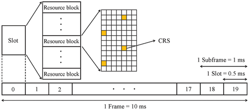
The LTE standard uses Orthogonal Frequency Division Multiplexing (OFDM) modulation to achieve robust transmission in multipath scenarios (Liu et al. Citation2014). In the LTE standard (E-UTRA Citation2019), OFDM signals are specified by three parameters, namely, the number of subcarriers or the Fast Fourier Transform (FFT) size, the sampling period, and the length of Cyclic Prefix (CP). In the LTE, the physical layer uses time-frequency resources for transmission. The smallest physical time-frequency resource consists of one subcarrier in one OFDM symbol, which is defined as a Resource Element (RE). The transmissions are scheduled in groups of 12 subcarriers, defined as Resource Blocks (RBs). The time-frequency resources are illustrated in , where the physical signal transmissions are organized into signal frames, subframes, and slots in the time-domain. Each signal frame has a duration of 10 ms and consists of 10 subframes with a subframe duration of 1 ms. A subframe is formed by 2 time slots, and each time slot consists of 7 OFDM symbols. The time interval of one OFDM symbol is 66.67 and the frequency spacing between two consecutive subcarriers is 15
.
Figure 2. LTE frame structure and mapping of the pilots of CRS to resource elements.
2.2. Synchronization signal
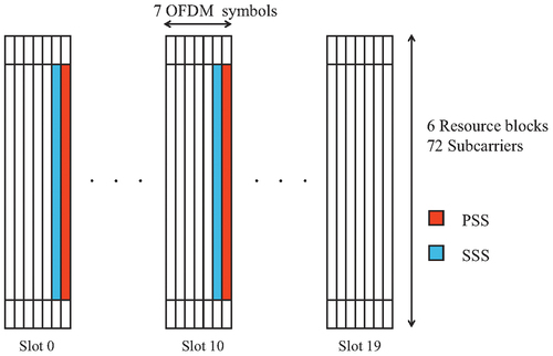
The synchronization signal is mainly used for cell search to establish communication between the BS and the user equipment in the LTE network (Das Citation2017). The synchronization signal consists of two different types of signals, i.e. the Primary Synchronization Signal (PSS) and the SSS. Both synchronization signals are generated by Zadoff-Chu sequences and mapped to 62 subcarriers in the center of the LTE transmission bandwidth (E-UTRA Citation2019). The protocols stipulate that there are 3 different PSS sequences, and each PSS sequence corresponds to 168 different SSS sequences. They are transmitted periodically in each frame of the LTE signals. shows the location of the synchronization signals in an LTE frame.
Figure 3. The location of the synchronization signal in the time-frequency grid of the 1.4 MHz bandwidth LTE signal.
2.3. Cell reference signal
The CRS is mainly used in LTE for downlink channel estimation. Based on the specific CID as well as the predefined antenna port, slot, and symbol indices in the LTE system, a unique CRS can be defined. Let us assume the total number of CRSs on an OFDM symbol is , then according to the LTE protocol (E-UTRA Citation2019), the CRS sequence
on each slot can be expressed as
where is the symbol position of the CRS signal in the time-domain,
and 4.
is the interval between two adjacent subcarriers. If
is the number of effective subcarriers for each symbol, the total number M can be calculated as
. The frequency-domain shift
depends on the CID, antenna port, and symbol indices.
2.4. Signal model
In the LTE network, SSS is designed for frame synchronization, and CRS can be used for channel estimation. From the perspective of indoor wireless positioning, the SSS and CRS are periodically transmitted in a fixed duration, which enables the receiver to continuously track the LTE signals for indoor wireless positioning. In this article, we develop the signal model for these pilot signals that can be used for wireless positioning.
Let us assume the LTE pilot signal (e.g. SSS or CRS) consists of subcarriers in the frequency-domain. Let
denote all subcarrier symbols within an OFDM symbol, where
represents the subcarrier number after the inverse fast Fourier transform operation. By adding the CP for every OFDM symbol, the samples of the transmitted baseband signal can be expressed as
where is the length of CP, and
.
In indoor environments, the LTE signal typically propagates along multiple paths, arising from reflection, scattering, and diffraction, which are due to daily human activities and many obstacles. Therefore, we assume that the LTE signal is transmitted on a frequency selective fading channel of length with complex path amplitudes
and the corresponding paths
.
At the receiver, there are usually several different errors such as Gaussian white noise, Symbol Timing Offset (STO), Carrier Frequency Offset (CFO), and Sampling Clock Offset (SCO). Among them, the STO is the deviation between the assumed and actual start time of one OFDM symbol. The CFO is caused by the mismatch between the receiver’s local oscillation frequency and the carrier of the received signal. The SCO is caused by the mismatch of the sampling clock frequency between the transceiver and the Doppler effect.
Hence, the received signal can be expressed as
where ,
and
stand for the amplitude, delay, and phase of the received signal of
path.
stands for the Line of Sight (LOS) signal and the others stand for the multipath signal.
is the sample of zero-mean complex Gaussian noise process with variance
. The phase
can be written as
where denotes the intermediate frequency,
denotes the Doppler frequency and
is the initial phase of the carrier. The timing point of the start of the FFT window is determined by the timing synchronization to be at the sample
, where
is a timing offset in units of OFDM samples.
3. TOA estimation based on carrier phase measurements for LTE positioning
The objective of the TOA estimation of the LTE signal is to find the starting point of the incoming OFDM symbols as accurately as possible. The received signals need to be completed in four steps to estimate the TOA of LTE signals, namely the coarse synchronization and demodulation, the time delay acquisition, the MEDLL algorithm, and the multipath anomaly detection. The multipath tracking SDR for LTE signal carrier phase TOA estimation is shown in . Among them, the coarse synchronization and demodulation are used to extract the pilot signals for the application of TOA estimation. The time delay acquisition is to obtain the initial value of TOA estimation for the first path and multipath of the received signal. The MEDLL algorithm is a method to achieve accurate tracking of the first path by eliminating multipath signal energy. Multipath anomaly detection is intended to improve the efficiency of the MEDLL algorithm, the primary purpose of which is to reduce the iteration time of the MEDLL algorithm without reducing its tracking accuracy . The methods are described in detail as follows.
Figure 4. Block diagram of multipath tracking SDR for LTE signal carrier phase TOA estimation.
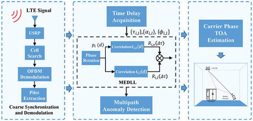
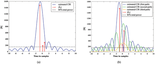
Figure 5. Comparison of the DLL algorithm and the MEDLL algorithm tracking process. (a) DLL. (b) MEDLL.
3.1. Coarse synchronization and demodulation
In the downlink of the LTE network, the user equipment firstly applied the step of cell search to obtain the CID and frame synchronization. The cell search consists of two steps: (a) by correlation with the 3 candidate sequences of PSS in time-domain with the received signal, the one giving the maximum value yields the estimated sequence for the PSS, i.e. . (b) by correlation with the 168 candidate sequences of SSS in time-domain with the received signal, the one giving the maximum value yields the estimated sequence for the SSS, i.e.
. Thus, the number of CID
is calculated as
where , and
. Correspondingly, the coarse start of the 10 ms frame timing of the LTE signals can be estimated. Based on the coarse synchronization results and the LTE protocol, the FFT is performed on the received signal to demodulate the OFDM signals and extract the pilot signals SSS/CRS (Zhang et al. Citation2012; Morelli and Moretti Citation2016).
It is noted that the coarse synchronization in the cell search process is for communication, and it can only perform signal synchronization for an integer number of sampling points. To achieve the purpose of positioning and navigation, further improvement steps are required to find more accurate symbol timing.
3.2. Time delay acquisition
The time delay acquisition step aims to reduce the residual errors resulted from the coarse synchronization and provides a more accurate start point as the initial value for the tracking step. In indoor environments, wireless signals experience the multipath fading, which is sometimes very severe. To improve timing accuracy, we try to detect each arriving path signal and estimate its time delay.
Denote as the local replica of the continuous and scatter pilots in the
th symbol, where
are the indices of the subcarriers of all the pilots in
. And let
denote the received symbols of the pilot subcarriers. According to the time shift property of the Fourier transform, the time delay estimation is equivalent to phase estimation in frequency-domain. Therefore, the time delay acquisition problem here is to find
and
that minimize the error between the received pilots and the local replica, described as
where is the number of multipaths,
is the channel amplitude of the
th path in the time of the
th symbol, and
is the corresponding time delay. We introduce the Matching Pursuit (MP) method (Cotter and Rao Citation2002; Chen et al. Citation2015) to solve the problem of (6). In order to simultaneously estimate the time delays and channel amplitudes, an order-recursive Least-Square MP (LS-MP) algorithm has been verified to be effective in our previous work (Chen et al. Citation2014, Citation2016). To apply the method for the current problem, we can obtain the arrival path information
as the initial value of time delay tracking.
For these detected arrival paths, a rule is formulated to select the paths applied for subsequent time delay tracking. First, the three paths with the top three highest channel amplitudes among the initial values are selected. Then, the earliest arrival and the second arrival path of the three paths are selected as the first and secondary paths of the received signal, respectively.
3.3. Multipath estimating delay lock loop
The MEDLL is an improved DLL where the multipath parameters are estimated to improve the Autocorrelation Function (ACF) of the first path signal (Townsend et al. Citation1995). The estimated ACFs of multipath signals are subtracted from the composite ACF to obtain the ACF of the LOS signal. As shown in , The MEDLL algorithm essentially adds a loop structure to implement multipath joint tracking to eliminate multipath error based on the DLL algorithm. Therefore, the tracking resolution of the MEDLL algorithm for the first path is related to the minimum correlation spacing of the DLL algorithm and the range of delays for which the synchronization may be achieved (Sanchez-Fernandez et al. Citation2007; Braasch Citation2001). The tracking resolution
of the MEDLL algorithm is set to 2 ns in this article.
After the time delay acquisition, to track a specific path, the receiver’s timing is first adjusted according to the estimated normalized symbol timing error, which can be expressed as
where is the estimated normalized symbol delay of the specific path of the received signal. Then, the pilot signals need to be cross-correlated with the local pilot signals to obtain an autocorrelation function. The ACF can be written as
where ,
is the number of reference pilot signals in each OFDM symbol. To obtain high-precision time delay variation estimation results, the Early-Minus-Late Power (EMLP) discriminator is used for tracking. Here, we first need to apply the local pilot signals to construct early and late reference pilot signals. The local generated early and late pilot signals are given by
where is the range of time delay estimation in EMLP, which is normalized to the signal sampling interval. Hence, we write the output of the early cross-correlation branch as
The normalized EMLP discriminator is expressed as
where the normalization factor (Chen et al. Citation2014; Chen Citation2015) holds
when
. By using the loop filter to smooth the discriminator
, the delay
, amplitude
, and phase
of the
th OFDM symbol can be updated by
where is the time delay variation value of the loop filter output of the
th OFDM symbol.
Based on the multipath signal model described before and the Minimum Mean Square Error (MMSE) principle, the estimates of ACF , amplitude
, delay
and phase
of the
th path signal can be expressed as
where is the cross-correlation function calculated based on the received signal and local pilot signal,
is the ACF of the local pilot signals. In addition, in indoor environments, severe multipath effects may cause the MEDLL algorithm multiple loop to fail to obtain a fitted solution. Limiting the number of loop iterations and restarting effective time delay tracking can improve the efficiency of the algorithm while maintaining tracking accuracy.
3.4. Multipath anomaly detection
The constantly iterative computational process of the MEDLL algorithm can significantly increase the calculation cost and reduce the operational efficiency of the algorithm. In response to this situation, this article adds a multipath anomaly detection process to the MEDLL algorithm which reduces the number of iterations of the MEDLL algorithm and improves the efficiency of the algorithm.
Severe multipath effects may cause multiple loop iterations to be unfitted when the MEDLL algorithm tracks the th OFDM symbol. Therefore, we re-enable the time delay acquisition process and use the result as the tracking result for the
th OFDM symbol when the number of iterations for an OFDM symbol is more than
. Where
is the empirical threshold, which is set to 10 in this article. Combining the MEDLL algorithm with the multipath anomaly detection algorithm enables the iterative calculation of mutually coupled multipath parameters in EquationEquations (15)
(15)
(15) –(Equation18
(18)
(18) ). The algorithm of the improved MEDLL can be expressed as follows
Algorithm. 1: The algorithm of the improved MEDLL.
The MEDLL algorithm needs to perform loop estimation to eliminate multipath signals. However, in our case, when ,
, which has little effect on the estimation accuracy of the first path. Therefore, we focus on the time delay tracking for two arrival paths in this article.
3.5. Carrier phase-based TOA estimation
Finally, the carrier phase of the first arrived path has been obtained during the time delay tracking (Chen et al. Citation2021). Correspondingly, the ranging estimation for indoor positioning is calculated as
where is the wavelength of the carrier, which for the LTE is about 0.16 m. In considering the pedestrian tracking for indoor navigation, there is no ambiguity problem existed. The reason is that the speed of a pedestrian walking indoor environment is usually less than 3 m/s, and the pilot signal period of LTE is less than 10 ms. Therefore, the phase difference between two adjacent pilot signals does not exceed one wavelength.
4. Test experiments in indoor environments
4.1. The self-built test platform for LTE signal sampling
As shown in , a test platform has been built for signal sampling and recording, which is based on a Universal Software Radio Peripheral (USRP). The USRP is a low-cost, flexible, and open-source device, which can be used for the acquisition and transmission of wireless signals (Chen et al. Citation2022; Liu et al. Citation2022a). In this work, USRP X310 is used, which has a main board integrated with a Kintex 7 FPGA. It allows receiving the signals with the carrier frequency in the range between 70 MHz and 6 GHz, as well as a bandwidth of up to 160 MHz. Such configurations can be well adapted for the sampling of the SSS and CRS of LTE signals. At the same time, to synchronize the local sampling clock with the GPS time, the USRP X310 is attached with a GPS Disciplined Oscillator module, which provides a 10 MHz reference input and allows the main oscillator to be monitored by GPS.
Figure 6. Experimental scenario and test bench. (a) USRP based SDR test bench. (b) diagram of experimental scenario and landmark points.
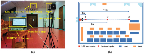
4.2. The experimental scenario
As shown in , the experimental scenario was selected a conference room on the fourth floor in a typical office building . There was a commercial LTE micro BS deployed by a mobile operator in the conference room. The LTE micro BS was located on top of the room at 3.30 m above the ground. According to the actual deployment of LTE BS by mobile operators, the LTE signals in Frequency Division Duplex (FDD) mode are used in this article. The acquisition parameters of the LTE signals are shown in .
Table 1. Signal acquisition parameters.
In order to verify the performance of TOA estimation using LTE signals in an indoor environment, static experiments and mobile experiments were carried out, respectively. During the static experiment, the signal was collected continuously at point O for 25 s. Two mobile experiments were conducted. In the first mobile experiment, the experimenter walked from point A to point B and back to point A at a constant speed. In the second mobile experiment, the experimenter walked from point C to point A and back to point C at a constant speed. It is worth noting that the signal antenna was kept at a height of 1.40 m above the ground throughout the experiment.
5. Experimental results
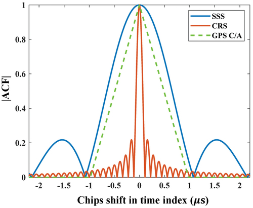
The ACFs (Chen et al. Citation2021) of SSS and CRS are shown in . To compare the performance of the two different pilot signals, the SSS and CRS were used for carrier phase-based TOA estimation, respectively. The multipath tracking SDR developed in this article is used to obtain ranging estimation. The SDR developed based on the DLL algorithm is used as a comparison method in this article.
Figure 7. The ACF of SSS, CRS, and GPS C/A.
5.1. Result of static experiment
shows the time delay results of the TOA estimation in the static experiment. Among them, shows the results of the time delay acquisition using the SSS. The multipath signal is not acquired because of the narrow bandwidth of the SSS. Therefore, shows the time delay tracking results of the DLL and MEDLL algorithms are similar. shows the results of the time delay acquisition using the CRS, which could be more accurately acquired for multipath signals because of the large bandwidth of CRS. Therefore, the MEDLL algorithm in achieves a more stable time delay result than the DLL algorithm through the detection and elimination of multipath signals. In order to evaluate the accuracy of the different methods, the Cumulative Distribution Function (CDF) and the boxplot of the TOA estimation time delay error in the static experiment are shown in . The Root Mean Square Error (RMSE), Maximum Error (ME), and probability error at 95% (2-σ) of the TOA estimation results in the static experiment are shown in .
Figure 8. Comparison of different signal results based on the DLL algorithm and MEDLL algorithm in the static experiment. (a) time delay acquisition results for SSS. (b) test results based on SSS. (c) time delay acquisition results for CRS. (d) test results based on CRS.
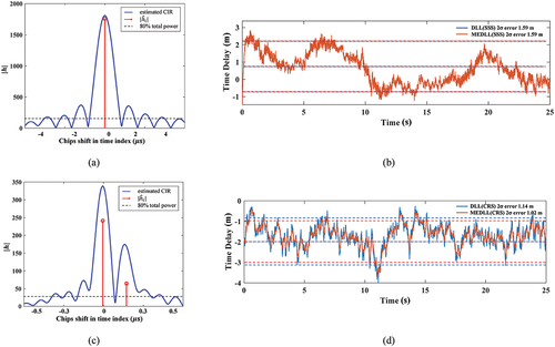
Figure 9. Comparison of statistical results under static conditions. (a) the CDF. (b) the boxplot.
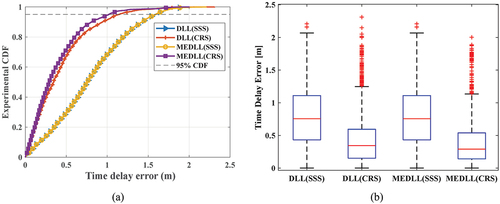
Table 2. The time delay error statistics in the static experiment.
For narrow bandwidth SSS, it was not possible to obtain sufficiently accurate multipath information through time delay acquisition. The performance of the DLL and MEDLL algorithms was similar when tracking the signal of only one path, and the probability time delay error at 95% was 1.59 m. For large bandwidth of CRS, it was possible to obtain accurate multipath information through time delay acquisition. The probability time delay error at 95% was reduced from 1.59 m to 1.14 m when tracking based on the CRS using the DLL algorithm. Moreover, the probability time delay error at 95% was further reduced from 1.14 m to 1.02 m when using the multipath tracking SDR.
5.2. Result of mobile experiment
shows the ranging estimation results in the mobile experiment. For these figures, the distance of the starting point is 0 m. When the experimenter walks toward the BS, the ranging result is positive, while the ranging distance is negative vice versa. The statistical results of the ranging estimation error in the mobile experiment are shown in . The ranging estimation error statistics in the mobile experiment are shown in .
Figure 10. Comparison of different signal results based on the DLL algorithm and MEDLL algorithm in mobile experiments. (a) the first mobile experiment. (b) the second mobile experiment.
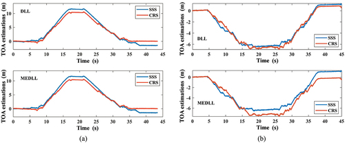
Figure 11. Comparison of the statistical results under moving conditions. (a) the CDF. (b) the boxplot.
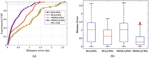
Table 3. The ranging estimation error statistics in mobile experiment.
For narrow bandwidth SSS, the ranging estimation based on the DLL and MEDLL algorithms was close. Moreover, the probability ranging estimation errors at 95% were above 2.30 m based on both the DLL and MEDLL algorithms. Compared with SSS, the probability ranging estimation error at 95% was reduced from 2.32 m to 1.33 m when tracking based on the CRS using the DLL algorithm. Moreover, the probability ranging estimation error at 95% was further reduced from 1.33 m to 1.17 m when using the multipath tracking SDR.
From the above, although the MEDLL algorithm could reduce the influence of indoor multipath effects on the accuracy of TOA estimation, the transmission bandwidth of the pilot signals could substantially affect the accuracy of the multipath tracking SDR. For large bandwidth of pilot signals, the developed SDR could identify multipath signals with some degree of accuracy while reducing its influence on the continuous tracking of the first path signal and improving the accuracy of carrier phase TOA estimation.
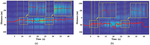
In order to verify the ability of the MEDLL algorithm to extract multipath information in indoor environments. A detailed analysis of the multipath tracking based on CRS in the first mobile experiment is presented in . Among them, ) show the relationship between the energy and time delay of the first and secondary paths of the received signal throughout the experiment, respectively. With the effect of multipath removed, there is no significant multipath signal energy in the first path and the tracking results for the first path are overall stable. As shown in , there were still residual weak effects of other path energies on both sides of the secondary path during continuous tracking. Considering both the computational cost and accuracy requirements, we argue that the influence of these path energies on the first path time delay tracking accuracy can be ignored at this point. On the other hand, significant path variations of three and six times were observed during the continuous tracking of the first path and the secondary path, respectively. The multipath anomaly detection algorithm quickly detected the occurrence of path signal anomalies in this process, reducing the number of MEDLL algorithm iterations and improving the overall SDR operation efficiency.
Figure 12. Results of the MEDLL algorithm for the extraction of multipath information. (a) the result of first path tracking. (b) the result of secondary path tracking. The blue background is the multipath signal energy separated by MEDLL, the red line is the position of the time delay at each moment, and the yellow dashed line is the time node at which the multipath anomaly detection algorithm detects the occurrence of path signal anomalies.
6. Conclusions
In this article, different pilot signals in LTE had been used for carrier phase TOA estimation in indoor environments. A multipath tracking SDR is developed based on the structural characteristics of LTE signals. The feasibility of LTE signals for indoor positioning was verified by the results of field experiments.
The results of experiments showed that both the SSS and the CRS can be used for TOA estimation in indoor positioning. Compared with SSS, the use of CRS for carrier phase TOA estimation can achieve higher accuracy and stability. Meanwhile, the results of several comparative experiments showed that the MEDLL algorithm can significantly improve the accuracy of TOA estimation for large bandwidth of pilot signals. On the other hand, the tracking results of the first path and the secondary path of CRS, respectively, showed that the use of the MEDLL algorithm can accurately extract the multipath information and effectively reduce the influence of the multipath effect on the accurate tracking of the first path. In the future, we will reduce the computational complexity of the time delay tracking algorithm while improving the accuracy and stability of the carrier phase TOA estimation.
Disclosure statement
No potential conflict of interest was reported by the author(s).
Data availability statement
The code applied in this study has not been made public because it involves subsequent research. Original data from part of the experiment can be obtained on reasonable request by contacting Zhaoliang Liu (E-mail: [email protected]).
Additional information
Funding
Notes on contributors
Zhaoliang Liu
ZhaoliangLiu received the MS degree from Wuhan University in 2020. He is currently a PhD student at the State Key Laboratory of Information Engineering in Surveying, Mapping and Remote Sensing at Wuhan University. His research interests include indoor positioning and navigation technology based on signal of opportunity, wireless communications, and the Internet of Things.
Liang Chen
LiangChen was a Senior Research Scientist with the Department of Navigation and Positioning, Finnish Geodetic Institute, Finland. He is currently a Professor with the State Key Laboratory of Information Engineering in Surveying, Mapping and Remote Sensing, Wuhan University, China. He has published over 70 scientific articles and five book chapters. His current research interests include indoor positioning, wireless positioning, sensor fusion, and location-based services.
Xin Zhou
XinZhou received the BS and MS degrees from Wuhan University in 2018 and 2020, respectively. He is currently pursuing the PhD degree in geodesy and survey engineering with the State Key Laboratory of Information Engineering in Surveying, Mapping and Remote Sensing, Wuhan University. His research interests include indoor positioning and navigation technology based on signal of opportunity, wireless communications, and the Internet of Things.
Nan Shen
NanShen is currently a PhD student at the State Key Laboratory of Information Engineering in Surveying, Mapping and Remote Sensing at Wuhan University. His research interests focus on precise GNSS data processing, software-defined receiver.
Ruizhi Chen
RuizhiChen is a professor at the State Key Laboratory of Surveying, Mapping and Remote Sensing Information Engineering, Wuhan University, and director of the laboratory. His main research interests include smartphone ubiquitous positioning and satellite navigation and positioning.
References
- Braasch, M. 2001. “Performance Comparison of Multipath Mitigating Receiver Architectures.” IEEE Aerospace Conference 3: 1309–1315. doi:10.1109/AERO.2001.931361.
- Chen, L., H. Kuusniemi, Y. Chen, J. Liu, L. Pei, and L. Ruotsalainen. 2015. “Constrained Kalman Filter for Indoor Blue-Tooth Localization.” In 2015 23rd European Signal Processing Conference (Eusipco 2015), 1915–1919. Nice. August 31. doi:10.1109/EUSIPCO.2015.7362717.
- Chen, R., and L. Chen. 2017. “Indoor Positioning with Smartphones: The State-Of-The-Art and the Challenges 2017.” Acta Geodaetica Et Cartographica Sinica 46 (10): 1316–1326. doi:10.11947/j.AGCS.2017.20170383.
- Chen, L., O. Julien, P. Thevenon, D. Serant, A. G. Pena, and H. Kuusniemi. 2015. “TOA Estimation for Positioning with DVB-T Signals in Outdoor Static Tests.” IEEE Transactions on Broadcasting 61 (4): 625–638. doi:10.1109/TBC.2015.2465155.
- Chen, L., H. Kuusniemi, Y. Chen, L. Pei, T. Kröger, and R. Chen. 2011. “Information Filter with Speed Detection for Indoor Bluetooth Positioning.” In 2011 International Conference on Localization and GNSS (ICL-GNSS), 47–52. Tampere. June 29–30. doi:10.1109/ICL-GNSS.2011.5955258.
- Chen, L., X. Lu, N. Shen, L. Wang, Y. Zhuang, Y. Su, and D. Li. 2022. “Signal Acquisition of Luojia-1A Low Earth Orbit Navigation Augmentation System with Software Defined Receiver.” Geo-Spatial Information Science 25 (1): 47–62. doi:10.1080/10095020.2021.1964386.
- Chen, L., L. Pei, H. Kuusniemi, Y. Chen, T. Kröger, R. Chen, et al. 2013. ”Bayesian Fusion for Indoor Positioning Using Bluetooth Fingerprints.” Wireless Personal Communications 70 (4): 1735–1745. doi:10.1007/s11277-012-0777-1.
- Chen, L., R. Piche´, H. Kuusniemi, and R. Chen. 2014. “Adaptive Mobile Tracking in Unknown Non-Line-Of-Sight Conditions with Application to Digital TV Networks.” EURASIP Journal on Advances in Signal Processing 2014 (1): 22. doi:10.1186/1687-6180-2014-22.
- Chen, L., P. Thevenon, G. Seco-Granados, O. Julien, and H. Kuusniemi. 2016. “Analysis on the TOA Tracking with DVB-T Signals for Positioning.” IEEE Transactions on Broadcasting 62 (4): 957–961. doi:10.1109/TBC.2016.2606939.
- Chen, L., X. Zhou, F. Chen, L. L. Yang, and R. Chen. 2021. “Carrier Phase Ranging for Indoor Positioning with 5G NR Signals.” IEEE Internet of Things Journal 1–1. doi:10.1109/JIOT.2021.3125373.
- Cherian, S. S., and A. N. Rudrapatna. 2013. ”LTE Location Technologies and Delivery Solutions.” Bell Labs Technical Journal 18 (2): 175–194. doi:10.1002/bltj.21612.
- Cotter, S. F., and B. D. Rao. 2002. “Sparse Channel Estimation via Matching Pursuit with Application to Equalization.” IEEE Transactions on Communications 50 (3): 374–377. doi:10.1109/26.990897.
- Dangermond, J., and F. G. Michael. 2020. “Building Geospatial Infrastructure.” Geo-Spatial Information Science 23 (1): 1–9. doi:10.1080/10095020.2019.1698274.
- Das, S. 2017. “LTE UE Operations Procedures and Anatomy.” In Mobile Terminal Receiver Design: LTE and LTE-Advanced, 140–173. Wiley. doi:10.1002/9781119107422.ch4.
- Del Peral-Rosado, J. A., et al. 2016. “Performance Analysis of Hybrid GNSS and LTE Localization in Urban Scenarios.” In 2016 8th ESA Workshop on Satellite Navigation Technologies and European Workshop on GNSS Signals and Signal Processing (NAVITEC), 1–8. December 14–16. doi:10.1109/NAVITEC.2016.7849332.
- Driusso, M., C. Marshall, M. Sabathy, F. Knutti, H. Mathis, and F. Babich. 2017. “Vehicular Position Tracking Using LTE Signals.” IEEE Transactions on Vehicular Technology 66 (4): 3376–3391. doi:10.1109/TVT.2016.2589463.
- E-UTRA (Evolved Universal Terrestrial Radio Access). 2019. “Physical Channels and Modulation, Document TS 36.211.” 3rd Generation Partnership Project (3GPP). September. [ Online]. http://www.3gpp.org/ftp/Specs/html-info/36211.htm
- Lee, D. H., H. Seo, B. Clerckx, E. Hardouin, D. Mazzarese, S. Nagata, K. Sayana, et al. 2012. “Coordinated Multipoint Transmission and Reception in LTE-Advanced: Deployment Scenarios and Operational Challenges.” IEEE Communications Magazine 50 (2): 148–155. doi:10.1109/MCOM.2012.6146494.
- Li, D., Z. Shao, and R. Zhang. 2020. “Advances of Geo-Spatial Intelligence at LIESMARS.” Geo-Spatial Information Science 23 (1): 40–51. doi:10.1080/10095020.2020.1718001.
- Liu, Z., L. Chen, X. Zhou, Y. Ruan, Z. Jiao, and R. Chen. 2022. “A Precise Ranging with Subcarrier Diversity for 5G NR Indoor Positioning.” The International Archives of the Photogrammetry, Remote Sensing and Spatial Information Sciences, XLVI-3/W1-2022: 125–131. doi:10.5194/isprs-archives-XLVI-3-W1-2022-125-2022.
- Liu, X., Z. Jiao, L. Chen, Y. Pan, X. Lu, and Y. Ruan. 2022. “An Enhanced Pedestrian Dead Reckoning Aided with DTMB Signals.” IEEE Transactions on Broadcasting 68 (2): 407–413. doi:10.1109/TBC.2022.3157475.
- Liu, Y., Z. Tan, H. Hu, L. J. Cimini, and G. Y. Li. 2014. “Channel Estimation for OFDM.” IEEE Communications Surveys & Tutorials 16 (4): 1891–1908. Fourthquarter. doi:10.1109/COMST.2014.2320074.
- Li, D., X. Zhao, and X. Li. 2016. “Remote Sensing of Human Beings–A Perspective from Nighttime Light.” Geo-Spatial Information Science 19 (1): 69–79. doi:10.1080/10095020.2016.1159389.
- Mondal, R. U., J. Turkka, and T. Ristaniemi. 2015. “An Efficient Cluster-Based Outdoor User Positioning Using LTE and WLAN Signal Strengths.” In 2015 IEEE 26th Annual International Symposium on Personal, Indoor, and Mobile Radio Communications (PIMRC), 2182–2186. Hong Kong. August 30 doi:10.1109/PIMRC.2015.7343659.
- Morelli, M., and M. Moretti. 2016. “A Robust Maximum Likelihood Scheme for PSS Detection and Integer Frequency Offset Recovery in LTE Systems.” IEEE Transactions on Wireless Communications 15 (2): 1353–1363. doi:10.1109/TWC.2015.2489206.
- Raquet, J., and R. K. Martin. 2008. “Non-GNSS Radio Frequency Navigation.” In 2008 IEEE International Conference on Acoustics, Speech and Signal Processing, 5308–5311. Las Vegas, NV. March 31. doi:10.1109/ICASSP.2008.4518858.
- Sanchez-Fernandez, M., M. Aguilera-Forero, and A. Garcia-Armada. 2007. “Performance Analysis and Parameter Optimization of DLL and MEDLL in Fading Multipath Environments for Next Generation Navigation Receivers.” IEEE Transactions on Consumer Electronics 53 (4): 1302–1308. doi:10.1109/TCE.2007.4429216.
- Shamaei, K. J. K., and Z. M. Kassas. 2018. ”Exploiting LTE Signals for Navigation: Theory to Implementation.” IEEE Transactions on Wireless Communications 17 (4 April): 2173–2189. doi:10.1109/TWC.2018.2789882.
- Shamaei, K., and Z. M. Kassas. 2018. “LTE Receiver Design and Multipath Analysis for Navigation in Urban Environments.” Navigation 65 (4): 655–675. doi:10.1002/navi.272.
- Townsend, B., R. Nee, V. P. Fenton, and K. van Dierendonck. 1995. “Performance Evaluation of the Multipath Estimating Delay Lock Loop.” ION GPS-95. January 18–20. doi:10.1002/j.2161-4296.1995.tb01903.x.
- Trinder, J., and Q. Liu. 2020. “Assessing Environmental Impacts of Urban Growth Using Remote Sensing.” Geo-Spatial Information Science 23 (1): 20–39. doi:10.1080/10095020.2019.1710438.
- Wang, P., and Y. J. Morton. 2020. “Multipath Estimating Delay Lock Loop for LTE Signal TOA Estimation in Indoor and Urban Environments.” IEEE Transactions on Wireless Communications 19 (8): 5518–5530. doi:10.1109/TWC.2020.2994037.
- Yan, J., Y. Cao, B. Kang, X. Wu, and L. Chen. 2021. “An ELM-Based Semi-Supervised Indoor Localization Technique with Clustering Analysis and Feature Extraction.” IEEE Sensors Journal 21 (3): 3635–3644. doi:10.1109/JSEN.2020.3028579.
- Yan, J., L. Zhao, J. Tang, Y. Chen, R. Chen, and L. Chen. 2018. “Hybrid Kernel Based Machine Learning Using Received Signal Strength Measurements for Indoor Localization.” IEEE Transactions on Vehicular Technology 67 (3): 2824–2829. doi:10.1109/TVT.2017.2774103.
- Yi, F. W. F. 2019. “China’s LTE Penetration Rate is as High as 78.3% with 5.58 Million 4G Base Stations.” CCTIME August (Online). http://www.cctime.com/html/2019-8-30/1469388.htm
- Zhang, Z., J. Liu, and K. Long. 2012. “Low-Complexity Cell Search with Fast PSS Identification in LTE.” IEEE Transactions on Vehicular Technology 61 (4): 1719–1729. doi:10.1109/TWC.2018.2789882.
- Zhou, X., L. Chen, J. Yan, and R. Chen. 2020. “Accurate DOA Estimation with Adjacent Angle Power Difference for Indoor Localization.” IEEE Access 8: 44702–44713. doi:10.1109/ACCESS.2020.2977371.