
 ?Mathematical formulae have been encoded as MathML and are displayed in this HTML version using MathJax in order to improve their display. Uncheck the box to turn MathJax off. This feature requires Javascript. Click on a formula to zoom.
ABSTRACT
Driven by improvements in satellite internet and Low Earth Orbit (LEO) navigation augmentation, the integration of communication and navigation has become increasingly common, and further improving navigation capabilities based on communication constellations has become a significant challenge. In the context of the existing Orthogonal Frequency Division Multiplexing (OFDM) communication systems, this paper proposes a new ranging signal design method based on an LEO satellite communication constellation. The LEO Satellite Communication Constellation Block-type Pilot (LSCC-BPR) signal is superimposed on the communication signal in a block-type form and occupies some of the subcarriers of the OFDM signal for transmission, thus ensuring the continuity of the ranging pilot signal in the time and frequency domains. Joint estimation in the time and frequency domains is performed to obtain the relevant distance value, and the ranging accuracy and communication resource utilization rate are determined. To characterize the ranging performance, the Root Mean Square Error (RMSE) is selected as an evaluation criterion. Simulations show that when the number of pilots is 2048 and the Signal-to-Noise Ratio (SNR) is 0 dB, the ranging accuracy can reach 0.8 m, and the pilot occupies only 50% of the communication subcarriers, thus improving the utilization of communication resources and meeting the public demand for communication and location services.
1. Introduction
With the development of satellite navigation and mobile communication technologies, the demand for high-precision location services has increased. Currently, the positioning technology used in satellite navigation systems is widely used in various fields, but navigation signals have a weak anti-interference ability (Chen et al. Citation2018). In urban canyons with indoor and outdoor occlusion and electromagnetic interference, there are problems such as weak signals, poor penetration, and unable to provide highly accurate location services (Jia et al. Citation2020; Zhu et al. Citation2018). An OFDM signal has wide coverage and strong anti-multipath, anti-fading, and anti-interference capabilities, which can compensate for the lack of navigation signals (Piccinni et al. Citation2020; Wang Citation2018). Therefore, the integration of communication and navigation systems based on LEO satellite communication constellations can improve the positioning accuracy and coverage of navigation systems (cao Citation2020; Cui and Shi Citation2013; Gaur and Prasad Citation2020; Guo et al. Citation2022; Yin et al. Citation2019; Wang et al. Citation2019).
In recent years, the integration and development of LEO navigation augmentation systems and satellite communication constellations have greatly promoted the integration of communication and navigation (Deng et al. Citation2021; Qu et al. Citation2017; Reid et al. Citation2018; Wang Citation2018; Wang et al. Citation2018a, Citation2019b). The integration of communication and navigation is important for continuously improving Positioning, Navigation, and Timing (PNT) services and is a popular research topic around the world (Benzerrouk et al. Citation2019; Leyva-Mayorga et al. Citation2020). In China, a team led by Professor Deng Zhongliang from Beijing University of Posts and Telecommunications has proposed Time and Code Division-Orthogonal Frequency Division Multiplexing (TC-OFDM), a design scheme for integrating communication and navigation at the signal level. The scheme superimposes a low-power directly spread navigation signal with high-precision ranging capability and an OFDM communication signal in the same time slot to form a TC-OFDM positioning signal (Yu Citation2013). A TC-OFDM positioning signal can achieve a positioning accuracy of 3 m in the horizontal direction and 1 m in the vertical direction for high-precision seamless indoor and outdoor positioning over wide areas. TC-OFDM is an integration method in the time domain (Liu Citation2019). A study also has proposed a signal integration method in the frequency domain, which superimposes navigation and communication signals to provide new concepts for integrating communication and navigation and continuously improves the overall performance of integrated systems (Liang Citation2019). Regarding the integration of communication and navigation, the first Iridium communication system was developed in the United States. The Iridium satellite system is a constellation of 66 satellites that are evenly distributed and can cover global regions, including polar regions. The main objective is to provide satellite communication services to users. In addition to providing communication services, the Iridium NEXT system also provides Satellite Time and Location (STL) services and can perform single-satellite positioning and timing tasks. In addition, the Iridium NEXT system has been used to improve Global Positioning System (GPS). While providing STL services, the GPS capabilities are backed up and enhanced. The communication satellites can provide navigation functions, and the indoor positioning accuracy can reach 20–50 m. Iridium STL signal design methods can provide reference for the integration of communication and navigation signal design based on new communication systems (Pratt et al. Citation1999; Qin et al. Citation2019).
The BeiDou-3 satellite navigation system has been in service for some time. The integration of communication and navigation based on communication constellations will play an important role in the construction of PNT systems (Chen et al. Citation2019; Guo et al. Citation2019; Hao et al. Citation2018; Lu et al. Citation2020). The LEO satellite navigation augmentation system is an enhancement of and complement to the Global Navigation Satellite System (GNSS) (Ge et al. Citation2018, Citation2021; Han et al. Citation2021; Li et al. Citation2019; Xu, Zhang, and Meng Citation2011; Zhang and Ma Citation2019). LEO satellite navigation augmentation ranging signals are broadcast to users by using mobile communication networks, which can assist users in obtaining global high-precision positioning services(Wang et al. Citation2020). In addition, with the increasing number of satellites and scarcity of available resources in frequency bands, the integration of communication and navigation can not only provide high-precision navigation and positioning services but also reduce frequency band resources by using satellite communication signals to broadcast navigation augmentation signals (Meng et al. Citation2018).
Therefore, to integrate communication and navigation, and improve the utilization of communication resources, this paper proposes the design of a new ranging signal based on the LEO communication constellation. The distance estimation value is obtained by using the time-frequency domain joint estimation method. The factors that affect the ranging accuracy and simulate the ranging performance of the new ranging signal are analyzed to continuously improve the utilization rate of communication resources while ensuring the ranging accuracy. The realization of the new ranging signal based on the LEO communication constellation will effectively improve multiple service capabilities and greatly promote the development of the location services industry (Wang et al. Citation2018b, Citation2019a, Citation2020; Wu, Sun, and Xie Citation2020a; Wu et al. Citation2020b).
2. Design of new ranging signals based on LEO satellite communication constellations
2.1. Iridium STL signal
The Iridium STL signal system combines satellite navigation and communication. The STL signal is a dedicated pulse signal achieved through an improvement in the paging channel of the original Iridium satellite communication system. The designed signal containing navigation and positioning information is a spread-spectrum Radio Frequency (RF) generated by the radio frequency modulation of the communication satellite signal pulse. The transmitted burst signal includes three components: Continuous-Wave (CW) mark, the PRN pilot code, and the navigation and positioning information. All components require specific coding, which provide the signal with high gain, strong landing power, strong penetration, and high resistance. Satellites with strong interference ability transmit signals in one direction, thereby not only improving the navigation and positioning performance of the signal but also greatly enhancing the GPS positioning, navigation, and timing capabilities (Xie Citation2019). The Iridium STL signal system is shown in .
Table 1. Iridium STL signal system.
In the above satellite communication system, the Iridium STL signal is transmitted by the paging channel, and the communication information is expressed in the same way as that in the Iridium System. It uses some time-frequency resources, divides the signal unit into the original time-frequency unit, and carries out the physical layer design of the signal, on the basis of which the signal ranging function is added to meet different PNT performance requirements. When the user initiates a call request, the user terminal is provided with PNT services. The design of the Iridium STL signal lays the foundation for designing integrated signals based on new satellite communication systems.
2.2. OFDM signal
The Iridium communication system was the first Global System for Mobile communication (GSM)-based LEO communication satellite systems proposed by the United States to achieve integration with GPS. It not only has satellite communication functions, but also has navigation and positioning enhancement functions, thus laying the foundation for developing LEO communication and integration. With the continuous updating of mobile communication technology, the future development requires a newer generation of communication systems.
OFDM is a key 4th-Generation (4 G) technology and the main basis for the signal system design of satellite internet. As the main modulation method in the 4G mobile communication system, OFDM is the most widely used multicarrier modulation transmission scheme (Huang and Wang Citation2018; Li, Wang, and Ding Citation2020). In the OFDM system, the transmitting end converts the transmitted digital signal into subcarrier amplitude and phase mapping, and performs Inverse Fast Fourier Transform (IFFT) operations to change the spectral expression of the data to the time domain. The IFFT can also be replaced by Inverse Discrete Fourier Transform (IDFT), which has the same effect, improves the calculation efficiency, and can be widely applied to all application systems. The receiving end performs the opposite operation and uses Fast Fourier Transform (FFT) for decomposition, and the amplitude and phase of the subcarriers are finally converted back to a digital signal. The OFDM system block diagram is shown in .
Figure 1. Block diagram of the OFDM system.
OFDM is a technology that divides the given channel into many orthogonal subchannels in the frequency domain and uses a subcarrier for modulation on each subchannel. Each subcarrier transmits in parallel and can thereby effectively combat multipath effects, eliminate Inter Symbol Interference (ISI), combat frequency selective fading, and achieve high channel utilization. OFDM can transmit data at high speeds in multipath and Doppler-shifted wireless mobile channels. Therefore, using the existing OFDM system in designing the navigation system of the LEO communication constellation can not only improve the ability of the navigation signal to resist interference and multipath, but also effectively save spatial frequency band resources, thereby greatly facilitating the development of the integration of communication and navigation (Voronkov, et al. Citation2018; Wu et al. Citation2022).
2.3 LSCC-BPR signal
With the continuous updating of mobile communication systems, the OFDM system has become the main basis for the design of integrated communication and navigation signals. Through serial-to-parallel conversion, the input high-speed data are converted into a multichannel parallel transmission of the low-speed data stream, this conversion greatly improves the information transmission rate and spectrum utilization. In the design of new ranging signals based on LEO communication constellations, the integration of the OFDM signal and ranging pilot signal can not only improve the anti-interference and anti-multipath capabilities of the navigation signal, but also effectively reduce the use of frequency band resources. The realization of integrated communication and navigation based on LEO communication constellations will continue to enhance satellite navigation capabilities (Zhou Citation2020).
In the existing OFDM communication system, and in the design of new ranging signals based on LEO communication constellations, the LSCC-BPR signal is composed of the OFDM signal and a Constant Amplitude Zero Auto Correlation (CAZAC) signal, which are superimposed in the same time slot. The CAZAC signal is transmitted in a block-type form by some OFDM subcarriers and remains continuous in the time and frequency domains. The LSCC-BPR signal continuously improves the ranging accuracy of the system and the utilization rate of communication resources without using too many communication resources.
2.3.1 Ranging pilot signal
In the integration of communication and navigation systems, the most used Zadoff-Chu sequence in a CAZAC sequence is selected as the ranging pilot and is defined as follows:
where M denotes the length of the Zadoff-Chu sequence, r denotes the reciprocal of M and is an integer, and k = 0,1 … , M-1.
A CAZAC sequence is characterized by sharp correlation peaks and zero side lobes, and the sequence remains a CAZAC sequence after Fourier transform application. In addition, a CAZAC sequence has a constant amplitude, and the Peak-to-Average Power Ratio (PAPR) is always 0 dB, therefore, these sequences can reduce the impact of PAPR values on the system, thereby making them a good choice for the design of integrated communication and navigation signals.
2.3.2 Generation of the LSCC-BPR signal
Driven by the enhancement of satellite internet and LEO navigation, to further realize integrated communication and navigation and improve the ranging accuracy, this paper proposes a new ranging signal design scheme based on LEO satellite communication constellations on top of OFDM technology for communication. The LSCC-BPR signal superimposes an OFDM signal and a CAZAC signal with a block-type structure so that the signal with ranging capability is fused to the OFDM signal. Using part of the subcarriers of the OFDM signal, positioning signals are transmitted to provide communication and high accuracy positioning services to users while ensuring no interference with each other. A block diagram of LSCC-BPR signal generation is shown in .
Figure 2. Block diagram of LSCC-BPR signal generation.
The ranging pilot is integrated with the OFDM signal in a block-type structure, and the LSCC-BPR signal structure is different due to the different insertion positions of the ranging pilot. This paper focuses on the ranging accuracy of the LSCC-BPR signal when the ranging pilot is inserted into the front, middle, and back of the subcarrier. The time-frequency structure and structure diagram of the signal are shown in
Figure 3. LSCC-BPR signal time-frequency structure.
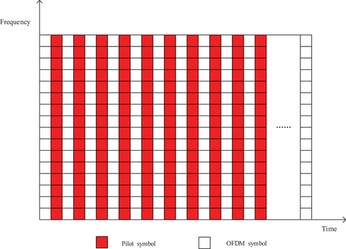
Figure 4. Schematic diagram of the LSCC-BPR signal structure. (a) Partial insertion of a pilot in front of the subcarrier. (b) Partial insertion of a pilot in the middle of the subcarrier. (c) Partial insertion of a pilot behind the subcarrier.
As shown in , the difference between the LSCC-BPR signal and the Positioning Reference Signal (PRS) in traditional 4 G is that the ranging pilot signal adopts a block-type structure. It is also integrated with the communication signal, and on-board ranging signals will occupy the same time and frequency resources as the communication information and remain continuous in the time-frequency domain. Thereby it ensures normal communication and ranging accuracy while greatly reducing the occupancy rate of the communication carrier. The realization of the LSCC-BPR signal will not only enable navigation augmentation of medium-orbit and high-orbit satellites, but also enable assisted ground base station positioning, thereby helping to solve indoor positioning problems.
3. Model of a new ranging signal system based on LEO satellite communication constellations
3.1 Traditional OFDM signal ranging system model
In an ideal OFDM signal ranging system, the transmit sequence is modulated to each of the different subcarriers by IFFT, and continuous ranging signals are generated. A block diagram of the OFDM ranging system is shown in .
Figure 5. Block diagram of the traditional OFDM ranging system.
Data transmitted by the OFDM ranging system can be expressed as:
where denotes the transmit sequence symbol, and symbols are assigned to all OFDM data; i denotes the i-th data message; N denotes the number of subcarriers; and T denotes the signal duration.
In the OFDM ranging system, the ranging pilot information is allocated to each subcarrier to provide the ranging pilot with continuity in the time and frequency domains. This method can be used to perform distance estimation and effectively suppress the fast-fading phenomenon caused by multiple paths and other factors. When ranging based on this ranging system, the ranging pilot is allocated to each communication subcarrier, which occupies too many communication resources and greatly reduces the utilization of communication resources. To improve the utilization of communication resources while ensuring the same ranging accuracy, a ranging system model of LSCC-BPR signals based on the original ranging model is proposed to reduce the proportion of communication resources occupied by ranging pilots.
3.2 Ranging system model of the LSCC-BPR signal
In the integration of communication and navigation systems, communication resources are used to complete ranging tasks. To save communication resources, firstly, the LSCC-BPR signal ranging system uses a block-type structure to send ranging pilots and modulates the ranging pilot information to some subcarriers. Secondly, the generated LSCC-BPR signal is used for distance estimation. Using a block-type structure to send ranging pilot signals without occupying all communication subcarriers ensures the continuity of ranging pilots in the time and frequency domains. Therefore, in ranging estimation, this approach greatly improves communication resource utilization. The ranging system of the LSCC-BPR signal is shown in .
Figure 6. Ranging system of the LSCC-BPR signal.
Compared with the traditional OFDM, the ranging system based on the LSCC-BPR signal mainly changes the structure of the sent ranging pilot by fusing it with the OFDM signal in a block-type structure and only a part of the communication subcarriers are occupied, thus ensuring the accuracy of ranging. At the same time, the utilization rate of communication resources is greatly improved. Since the ranging system will be applied to LEO satellites, the LEO satellites will run quickly and produce a large Doppler shift, which will have a greater impact on the orthogonality of the signal. The processing unit added to the ranging system mainly estimates, predicts, and compensates for the Doppler shift, thus reducing the impact of the Doppler shifts on the ranging accuracy. Therefore, it is necessary to estimate and compensate for the Doppler shift before ranging (Hsu and Jan Citation2014; Li et al. Citation2016; Li, Zhao, and Pei Citation2018; Niu Citation2020).
LEO satellites usually revolve around the earth at a constant speed in a circular orbit between 500 km and 2000 km. The Doppler shift of an LEO at any point P can be calculated based on the ground position information, which is expressed as:
Among them.
where denotes the Earth’s radius,
denotes is the orbital radius;
denotes the estimated angular distance of the Earth’s surface along the satellite’s orbit;
denotes the maximum elevation angle, and
denotes the satellite’s angular velocity, which can be approximated as a constant.
where denotes the average angular velocity of the satellite’s motion,
denotes the angular velocity of the Earth’s rotation, and i denotes the inclination of the satellite’s orbit.
According to EquationEquation 3(3)
(3) , the downlink Doppler shift in the L-band can range from −35 kHz to 35 kHz. The change in the position of the mobile terminal makes the Doppler shift change, generally for a high-speed moving object. Due to the change in position, the maximum Doppler shift generated by the satellite is approximately 36 kHz. It is possible to use ephemeris for pre-compensation before ranging, thus reducing the interference between subcarriers and the impact of Doppler shift on ranging accuracy.
After Doppler frequency offset compensation, when the pilot signal adopts a block-type structure, it can occupy subcarriers at different locations. This article discusses only the three forms shown in In the LSCC-BPR signal ranging system, according to the position where the ranging pilot is inserted, as shown in , the signal transmitted by the LSCC-BPR signal system can have three representations.
, data transmission by the LSCC-BPR ranging system can be expressed as:
where M denotes the number of ranging pilots, M ≤ N, and T denotes the signal duration.
, data transmission by the LSCC-BPR ranging system can be expressed as:
, data transmission by the LSCC-BPR ranging system can be expressed as:
For data transmitted through a Gaussian white noise channel, after a transmission delay τ, the data are received by the receiving end, this process is expressed as:
where A denotes the amplitude of the data after transmission through the channel, τ denotes the transmission time delay, and n(t) denotes Gaussian white noise.
4. Ranging algorithm based on the LSCC-BPR signal
The ranging based on the LSCC-BPR signal is based mainly on Time of Arrival (TOA) algorithms, which estimate the time delay of a continuously received signal in the time and frequency domains and then yield the corresponding distance value (Li et al. Citation2022). When the ranging pilot adopts the block-type pilot structure, the ranging pilot not only ensures the continuity of the pilot signal in the time-frequency domain, but also greatly saves communication resources. The algorithm flow is shown in .
Figure 7. Ranging algorithm flow based on the LSCC-BPR signal.
As shown in , when the ranging system uses the generated LSCC-BPR signal for ranging estimation, first, the integer delay estimation is performed in the time domain to obtain the integer delay estimation value, but the fractional delay cannot be estimated. Thus, after the integer delay is estimated, the signal is converted to the frequency domain, and when the frequency domain delay is estimated, the fractional delay estimation value is obtained. Finally, an estimate of the distance is obtained.
4.1 Time delay estimation in the time domain
Equations (9), (10), and (11) for received data involve sampling at , sampling intervals to obtain the data. The sampled received data are expressed as:
where denotes the sampling interval and
.
The local data generated at the receiver side are expressed as:
where m denotes the sampling start position and τ denotes the transmission delay.
The sampled data are autocorrelated with the local data.
The peak value of the autocorrelation function R(m), that is, the value of m, must be determined.
The time-domain delay estimation result is:
4.2 Time delay estimation in the frequency domain
Since only integer multiples of the time delay can be estimated in the time domain, the fractional multiples of the time delay are estimated in the frequency domain.
The received data in EquationEquations (12)(12)
(12) , (Equation13
(13)
(13) ), and (Equation14
(14)
(14) ) are sampled at
, sampling intervals and expressed as:
where i denotes the serial number of the sampling point, and denotes the decimal transmission delay.
The FFT is performed separately for time-domain sample sequences and
. Due to the time delay for the data in the time domain,
and
generate phase differences in the frequency domain, and fractional time delay estimation is performed based on the generated phase differences.
After the integer delay is estimated, the FFT is performed on time-domain sampled signals and
to obtain frequency-domain data
and
.
Then, the phase of is:
denotes the estimated value of the difference in the phase offsets separated by L subcarriers.
where L denotes the frequency domain correlation interval, which can be adjusted randomly.
The distance calculation is based on the following formula:
The LSCC-BPR signal ranging algorithm finds the integer delay estimation value in the time domain by searching the correlation peak of the signal. In the frequency domain, the decimal delay value is determined by finding the phase difference caused by the delay. After joint estimation in the time and frequency domains, a more accurate distance estimate can be obtained.
5. Distance measurement simulation results and performance analysis
To determine reasonable simulation parameters for the LSCC-BPR signal ranging system and reduce the ranging error, this paper analyses the factors affecting the ranging accuracy. After determining reasonable simulation parameters, a ranging accuracy performance analysis is carried out. In the ranging simulation, the system simulation parameters include bandwidth B = 20 MHz, sampling interval time QUOTE
= 0.05 µs, signal duration
, fractional time delay of signal transmission
QUOTE
, and L/N is any value between 0.1 and 1.
5.1 Analysis of factors affecting ranging accuracy
5.1.1 Influence of m on integer delay estimation
Because the value of m can be an integer or fraction when sampling, the following simulations are carried out to analyze the effect of time domain delay on the estimation for different values of m. The number of subcarriers is 512, 1024, 2048, and 4096, the integer part of m is taken as 256, 512, 1024, and 2048, and the fractional part is taken as 0.1 ~ 0.5 for simulation to observe the degree of influence of fractional sampling on the estimation of time-domain delay, and then, the fractional value range of m is determined. The effect of fractional sampling on the estimation of time delay when the number of subcarriers is 512, 1024, 2048, and 4096 is shown in , respectively.
Figure 8. Time delay estimation based on fractional sampling. (a) When the number of carriers is 512. (b) When the number of carriers is 1024. (c) When the number of carriers is 2048. (d) When the number of carriers is 4096.
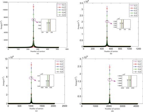
As shown in , regardless of the number of subcarriers, when the fractional part of m is set to 0.1 ~ 0.4, there is no effect on the appearance of related peaks in the time domain estimation, and integer time delay estimation yields an accurate value. However, fractional time delay estimation cannot be performed. When the fractional part of m is set to 0.5, the appearance of related peaks occurs, and the integer estimation time delay value cannot be accurately estimated. Therefore, when time delay estimation is performed in the time domain, the delay value should be in the range of 0.1 to 0.4, time delays based on integer time sampling can be estimated, and a fractional time delay will cause errors in integer time delay estimation. Thus, fractional time delay estimation needs to be performed in the frequency domain.
Simulations of time-domain delay estimation are performed for different SNRs, the integer part of m is set to 1000, the decimal part of m ranges from 0.1 ~ 0.4, and the number of subcarriers is 4096. The results are shown in .
Figure 9. Simulation of time-domain delay estimation for different SNRs.(a) When the SNR is −5 dB. (b) When the SNR is −10 dB. (c) When the SNR is −15 dB. (d) When the SNR is −20 dB.
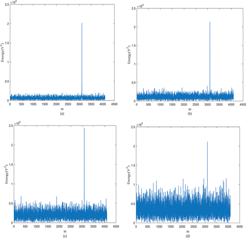
As shown in , for different SNRs, there is no effect on the autocorrelation of the ranging pilot. When the integer part of m is set to 1000, the position of the correlation peak is 3096, that is, the integer multiple of the delay is 1000 times the sampling interval. Therefore, when performing frequency-domain delay estimation, there is no error in time-domain delay estimation, and the influence on the ranging error comes mainly from delay estimation in the frequency domain.
5.1.2 Influence of the frequency-domain correlation interval L on the ranging accuracy
EquationEquation (24)(24)
(24) shows that L is a factor that affects the frequency domain time delay estimation. When the value of L is too small, the fractional delay estimate may exceed the actual estimate; when L is too large, the fractional delay estimate may be much smaller than the real value. Therefore, it is important to determine the value of L for the frequency domain delay estimation. Determining this value requires that the impact on the range accuracy for different values of L be determined in the experimental simulation stage, and then the value of L should be determined to provide reasonable parameter support for the subsequent simulation experiments.
According to the above analysis, the fractional time delay of the signal transmission chosen for the simulation is . To determine the effect of the frequency domain correlation interval L on the accuracy of the frequency domain estimation, simulations of the effect of L on the ranging error are performed for different values of L. Simulation of the ranging error is carried out for different values of L/N at SNRs of −5 dB, −10 dB and −15 dB, and the appropriate value of L/N is found. The relationship between L/N and the ranging error for a nonblock-type structure at different SNRs is shown in .
Figure 10. Relationship between L/N and ranging error.
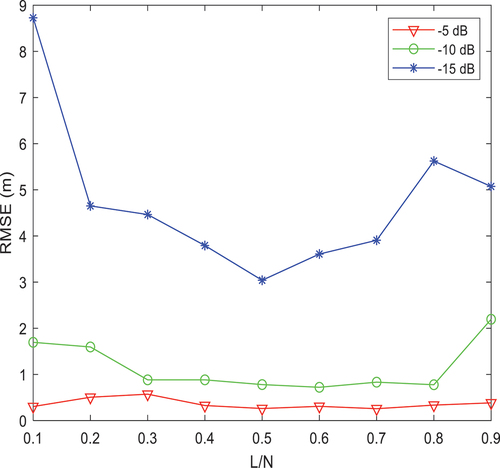
As shown in , when the value of L/N is constant, the smaller the SNR is, the larger the error. For the same SNR case, when the value of L/N increases, the ranging error is relatively constant but is still affected by noise. When the SNR is large (i.e. the signal is noisy), the error increases, but the choice of the best L/N value is generally unaffected. When the SNR is −15 dB and the value of L/N is 0.3 ~ 0.7, the range error does not fluctuate much, and the range error is 3 ~ 4 m; at this time, the L/N value that has the least influence on the range is 0.51. When the SNR is −10 dB and the value of L/N is 0.3 ~ 0.7, the range error is the lowest and the range error is approximately 1 m; at this time, the best value of L/N is 0.62. When the SNR is −5 dB, with different values of L/N, the range error is below 1 m, at this time, the best value of L/N is 0.53. In general, for different SNRs, when L/N = 0.55, the ranging error is the lowest. Therefore, when the block-type pilot is used for ranging, L/N = 0.55 is selected in simulations.
5.1.3 Influence of the number of subcarriers on the ranging accuracy
The bandwidth, sampling interval, and fractional time delay are the same as those in the above simulation, and L/N = 0.55. For the OFDM ranging signal, when the pilot signal is assigned to each subcarrier, the ranging accuracy at different SNRs is evaluated for various numbers of subcarriers: N = 4096, 2048, 1024, and 512. The simulation results are shown in .
Figure 11. Relationship between ranging error and SNR for different numbers of subcarriers.
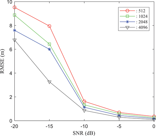
As shown in , under the same conditions, the ranging error decreases as the SNR decreases. For the same SNR, as the number of subcarriers increases, the ranging accuracy increases. Therefore, to ensure a high range accuracy, 4096 subcarriers are chosen for the simulation with a block-type structure for range measurement.
5.2 Ranging simulation based on the LSCC-BPR signal
The following simulations are based on the ranging algorithm for LSCC-BPR signals.
5.2.1 Simulation of ranging accuracy with different numbers of pilots at the same position
When the value of L/N is 0.55; the bandwidth B = 20 MHz; the number of subcarriers N = 4096; the sampling interval the signal duration
; the fractional time delay of signal transmission
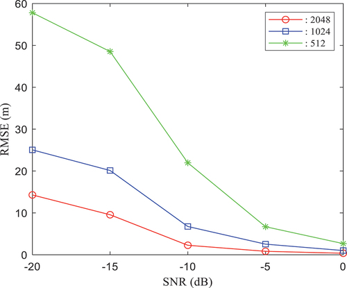
and the number of ranging pilots is 2048, 1024, and 512. The ranging accuracy is evaluated for different SNRs. Ranging pilot information is inserted into the front, middle, and back of subcarriers. The ranging accuracies of 2048, 1024, and 512 pilots with different SNRs are shown in , respectively.
Figure 12. Relationship between ranging error and SNR when the ranging pilots are inserted in the front.
As shown in , the ranging error is the lowest when the number of pilots is 2048 at the same SNR; when the number of ranging pilots is the same, the ranging accuracy decreases as the SNR decreases. In the case of different pilot numbers, when the SNR is 0 dB, the ranging error is basically the same; at this time, the ranging accuracy can reach 1 m when the pilot number is 2048, the ranging accuracy is basically the same as it is when the block-type ranging pilots are not used, and the utilization rate of communication resources is improved by 50%.
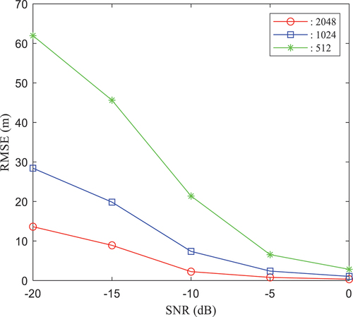
Figure 13. Relationship between ranging error and SNR when the pilots are inserted in the middle.
As shown in , when the pilots are inserted into the middle of the subcarrier, the ranging error decreases continuously with the increase in the number of pilots at the same SNR; when the number of pilots is the same, the ranging accuracy decreases with the decrease in the SNR. When the SNR is 0 dB, the ranging error is below 3 m regardless of the number of pilots. At this time, when the number of pilots is 2048, the ranging accuracy can reach 0.8 m, which is the same as when block-type ranging pilots are not used, and the utilization rate of communication resources is improved by half.
Figure 14. Relationship between ranging error and SNR when the pilots are inserted in the back.
As shown in , when the ranging pilots are inserted into the back of the subcarrier, the main factor affecting the ranging error is still the SNRs and the number of ranging pilots. This result is basically the same as the trend of the ranging error shown in . When the SNR is 0 dB, the ranging error is within the acceptable range for different numbers of ranging pilots, and the ranging pilot occupies a few communication subcarriers, thereby greatly improving the utilization of communication resources.
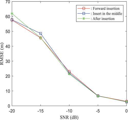
5.2.2 Simulation of ranging accuracy for the same number of pilots at different positions
Parameters, such as bandwidth, sampling interval, and fractional delay, are the same as in the above simulation. When the range pilot information is inserted into the front, middle, and back of the subcarrier, range accuracy simulations are carried out at different locations with different SNRs for the same number of pilots. The ranging accuracies at different SNRs for 2048, 1024, and 512 ranging pilots are shown in , respectively.
Figure 15. Relationship between the ranging error and SNR at different positions with 2048 pilots.
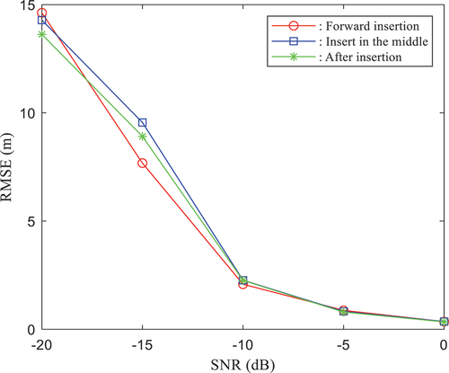
As shown in , at the same or different SNRs, the ranging accuracy is independent of the position of the pilot data insertion, and the ranging accuracy is almost constant. When the SNR is from 0 dB to −10 dB, the ranging accuracy at different positions is more or less the same; when the SNR is between −10 dB and −15 dB, the ranging error is lower when the pilots are inserted in front of the subcarrier, but the difference between the top and bottom is not large; when the SNR is between −15 dB and −20 dB, the ranging error is not large between the top and bottom. Therefore, when the number of pilots is 2048, the ranging error at different positions is basically the same, and the position of insertion has little influence on the ranging error. When the SNR is 0 dB, the ranging error at different positions can reach 0.8 m, the communication resource is improved by 50%, and the ranging accuracy is the same as when the block-type ranging pilots are not used.
Figure 16. Relationship between the ranging error and SNR at different positions with 1024 pilots.
As shown in , when the number of pilots is 1024, with the change of SNRs, the position of the ranging pilot insertion has little effect on the ranging accuracy, and the ranging error is approximately the same. In the case of 0 dB, the ranging error can reach 1 m when the pilots are inserted into different positions. Not only does the communication resource utilization rate increase by 75%, but the ranging accuracy is basically the same as that in the case without the block-type structure.
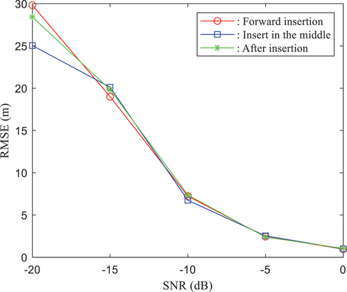
Figure 17. Relationship between the ranging error and SNR at different positions with 512 pilots.
As shown in , when the number of pilots is 512, for different SNRs, the ranging accuracy is reduced compared with 2048 and 1024 pilots. Additionally, the position of pilot insertion has little effect on the ranging accuracy. When the pilots are inserted at different positions and the SNR is 0 dB, the ranging error can reach 2 m. This result is a 12.5% improvement in communication resource utilization. Obviously, the ranging error is affected by noise and is in an unacceptable range when the SNR is small.
5.2.3 Effect of Doppler frequency bias on ranging accuracy
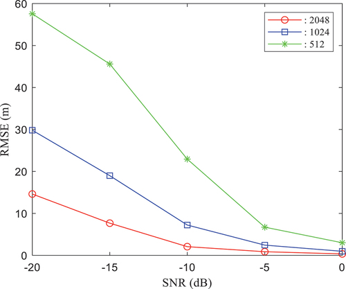
The bandwidth, sampling interval time and fractional time delay are the same as the above simulation conditions, and the ±36 kHz Doppler shift is added to simulate the ranging accuracy at the same position with different SNRs of 2048, 1024, and 512 ranging pilots. The simulation of the effect of the Doppler shift on the ranging accuracy is shown in .
Figure 18. Effect of the Doppler shift on ranging accuracy.
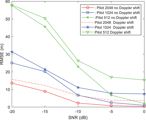
As shown in , when there is a Doppler shift in the ranging system, there is a certain magnitude of reduction in the ranging error after the Doppler shift is compensated. As the number of ranging pilots decreases, the effect of the Doppler shift on ranging accuracy increases. When the SNR is 0 dB and the number of ranging pilots is 2048, the ranging accuracy decreases from 0.8 m to approximately 3 m, due to the effect of the Doppler shift on the phase of the LSCC-BPR signal. Therefore, Doppler shift compensation should be performed before ranging to reduce the effect of the Doppler shift on ranging.
5.2.4 Simulation of ranging accuracy for the traditional OFDM signal and the LSCC-BPR signal
shows that when the block-type pilot is used, when the number of pilots is 2048, the ranging accuracy can be the same as that when the block pilot is not used. Therefore, the ranging accuracy of the traditional OFDM signal and the LSCC-BPR signal are compared, and the ranging accuracy and the carrier occupancy rate are analyzed. When the number of subcarriers is 4096 and 2048 and the number of pilots is 4096 and 2048, the simulation of ranging accuracy with and without the block-type structure is shown in .
Figure 19. Ranging accuracy simulation based on the traditional OFDM signal and the LSCC-BPR signal.
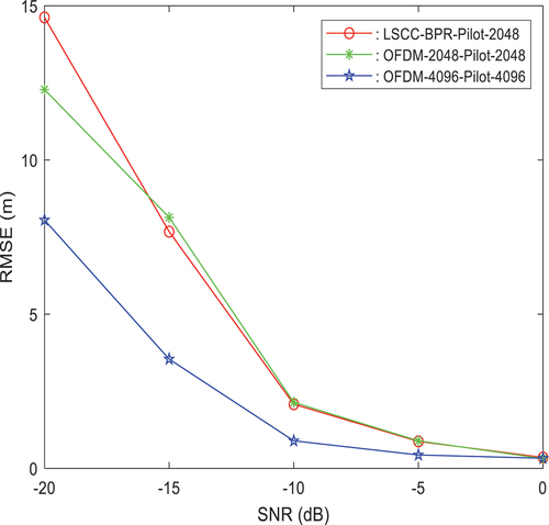
As shown in , when the number of subcarriers is 4096, the ranging accuracy based on the traditional OFDM signal is compared with that based on the LSCC-BPR signal. At 0 dB, the ranging accuracy is basically the same. At this time, the ranging pilot occupies only 50% of communication resources, thereby reducing the carrier occupancy rate. When the number of subcarriers is 2048, with the change in the SNR, when the LSCC-BPR signal is used, the ranging accuracies are basically the same. At 0 dB, the block-type structure is used for ranging, this can improve the utilization rate of communication resources while ensuring the ranging accuracy.
5.2.5 Comparison of ranging based on the CSS signal and LSCC-BPR signal
The Chirp Spread Spectrum (CSS) signal technique is a common spread spectrum technique and an important way to achieve TOA localization (Jiang Citation2018; Daniel et al. Citation2021). The principle is to compress the pulse of the linear Frequency Modulation (FM) signal by a matching filtering technique similar to autocorrelation. The signal will form an energy peak at one moment, and the time of receiving the signal will be determined according to the peak to achieve ranging (Qian, Ma, and Liang Citation2019; Sha Citation2016; Wu Citation2013). The simulation parameters are consistent with the above simulation parameters. The integer time delay is 50 µs, the fractional time delay is 0.02 µs, and CSS signal is simulated for ranging. The estimated time delay of the CSS signal with the SNR of 0 dB is shown in .
Figure 20. CSS signal time delay estimation with the SNR of 0 dB.
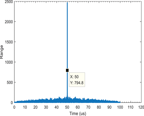
As shown in , when the SNR is 0 dB, the integer time delay can be accurately derived as 50 µs according to the location of the peak occurrence, but the fractional time delay is not estimated. Since the time resolution is affected by the bandwidth, the fractional delay estimation is affected.
When the SNR is at 0 dB, shows the comparison of ranging performances of the CSS and LSCC-BPR signals.
Table 2. Comparison of ranging performances of the CSS and LSCC-BPR signals.
shows that the CSS signal and the LSCC-BPR signal have their own advantages and disadvantages in ranging. To save space frequency resources, the LSCC-BPR signal can be selected for ranging.
5.3 LSCC-BPR signal resource utilization analysis
In ranging based on the new OFDM ranging signal, the ranging pilots adopt the block-type structure and are inserted into the subcarriers in different positions to complete the ranging task. At this time, the ranging pilots occupy only part of the subcarriers, and the remaining empty subcarriers transmit other communication information. When the number of pilots is 512, 1024, and 2048, the proportions of subcarriers occupied by pilot data are shown in .
Figure 21. Proportions of pilots, information, and subcarriers.
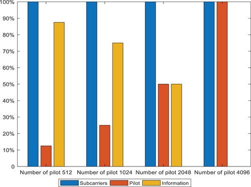
Since the position of pilot information insertion does not affect the ranging accuracy, according to the above simulation results, when the SNR is 0 dB, with the increase in the number of pilots, the ranging accuracy is also improved. shows the ranging accuracy at a SNR of 0 dB for different numbers of pilots.
Table 3. Ranging accuracy for different numbers of pilots at an SNR of 0 dB.
As shown in and , the ranging pilots occupy fewer subcarriers, the greater the number of subcarriers used to transmit communication information, the lower the carrier occupancy rate, and the higher the communication resource utilization rate. When the pilot data occupy 50% of the subcarriers, the ranging accuracy is basically the same as that when all subcarriers are occupied by pilots. While ensuring the ranging accuracy, the ratio of the ranging pilots occupied by the communication carrier is reduced, and the communication resource utilization rate is greatly improved.
6. Conclusions
In this article, the design of the LSCC-BPR signal is mainly proposed, and based on this signal, an analysis of the impact of this signal on ranging accuracy and resource utilization is performed. The LSCC-BPR signal combines the block-type ranging pilot with the OFDM signal, which can not only complete the ranging task but also transmit communication information normally. Compared with the traditional ranging signal, the ranging information in the LSCC-BPR signal occupies only part of the communication resources, thereby greatly improving the utilization rate of the communication resources. According to the analysis of the simulation results, it’s concluded that when the LSCC-BPR ranging system is used, with ranging pilots’ number of 2048 and the SNR of 0 dB, the ranging accuracy is the same as that using a traditional OFDM ranging system, and the accuracy can reach 0.8 m and occupy only 50% of the communication subcarriers, thereby greatly reducing the occupancy rate of the communication carriers. The realization of the LSCC-BPR signal can not only effectively solve the lack of frequency resources but also assist the navigation system in high-precision positioning. Therefore, the LSCC-BPR signal is applied to the LEO satellite constellation to provide inspiration for further the integration of communication and navigation
Disclosure statement
No potential conflict of interest was reported by the author(s).
Data availability statement
The data that support the findings of this study are available from the corresponding author upon reasonable request.
Additional information
Funding
Notes on contributors
Jingfang Su
Jingfang Su is a postgraduate in Information Science and Engineering, Hebei University of Science and Technology. Her research interests are wireless communication technology, integration of communication and navigation, and LEO navigation.
Jia Su
Jia Su is an associate professor in Dept. of School of Information Science and Engineering, Hebei University of Science and Technology. She received the PhD degree from Harbin Engineering University. Her research interests are wireless communication technology, object detection, and tracking.
Qingwu Yi
Qingwu Yi is the Director of State Key Laboratory of Satellite Navigation System and Equipment Technology. His research interests are satellite navigation systems and equipment-related technologies, time-frequency technologies.
Cailun Wu
Cailun Wu is the Deputy director of the State Key Laboratory of Satellite Navigation System and Equipment Technology. He received his Ph.D. degree from the Tsinghua University. His research interests are navigation signal design and LEO navigation system design.
Weimin Hou
Weimin Hou is a professor in Dept. of School of Information Science and Engineering, Hebei University of Science and Technology. He received the PhD degree from Institute of Acoustics, Chinese Academy of Sciences. His research interests are remote sensing signal processing and artificial intelligence.
References
- Benzerrouk, H., Q. Nguyen, X. X. Fang, A. Amrhar, and R. Landry. 2019. “Alternative PNT Based on Iridium Next LEO Satellites Doppler/ins Integrated Navigation System.” In Paper presented at the Proceedings of the 2019 26th Saint Petersburg International Conference on Integrated Navigation Systems (ICINS), St. Petersburg, Russia, May 27-29. doi: 10.23919/ICINS.2019.8769440.
- Cao, J. M. 2020. “Design and Performance Analysis of a Novel Positioning-communication Integrated Signal for 5G Positioning.” Master diss., Beijing University of Posts and Telecommunications. doi:10.26969/d.cnki.gbydu.2020.001768.
- Chen, Y. M., T. Li, Y. P. Cui, Z. Li, M. Gao, and L. Zhou. 2018. “Research on Indoor and Outdoor Integrated Location Service Technology.” In Paper presented at the Proceedings of the 2018 International Conference on Intelligent Transportation, Big Data & Smart City (ICITBS), Xiamen, China, January 25-26, 117–120. doi: 10.1109/ICITBS.2018.00038.
- Chen, S., R. Zhang, Y. C. Ren, Y. Q. Wang, B. Niu, and H. S. Chen. 2019. “The Start Time to First Fix Test of BDS New Signal Structure Receiver.” Science of Surveying and Mapping 44 (6): 84–88. doi:10.16251/j.cnki.1009-2307.2019.06.012.
- Cui, J. X., and H. L. Shi. 2013. “Satellite Communication and Navigation Integrated Signal.” Telkomnika Indonesian Journal of Electrical Engineering 11 (8). doi:10.11591/telkomnika.v11i8.3034.
- Daniel, E.-R., J. A. López-Salcedo, G. Seco-Granados, and E. Falletti. 2021. “Comparison of Several Signal Designs Based on Chirp Spread Spectrum (CSS) Modulation for a LEO PNT System.” In Paper presented at the Proceedings of the 34th International Technical Meeting of the Satellite Division of The Institute of Navigation (ION GNSS+ 2021), St. Louis, Missouri, September 20-24, 2804–2818. doi: 10.33012/2021.18010.
- Deng, R. Q., B. Y. Di, H. L. Zhang, L. L. Kuang, and L. Y. Song. 2021. “Ultra-Dense LEO Satellite Constellations: How Many LEO Satellites Do We Need?” IEEE Transactions on Wireless Communications 20 (8): 4843–4857. doi:10.1109/TWC.2021.3062658.
- Gaur, D., and M. S. Prasad. 2020. “Satellite Constellation Stationing Effects on Communication Networks.” In 2020 Paper presented at the Proceedings of the 8th International Conference on Reliability, Infocom Technologies and Optimization (Trends and Future Directions) (ICRITO), Noida, India, June 4-5, 1189–1194. doi: 10.1109/ICRITO48877.2020.9197767.
- Ge, H. B., B. F. Li, M. R. Ge, N. Zang, L. W. Nie, Y. Z. Shen, and H. Schuh. 2018. “Initial Assessment of Precise Point Positioning with LEO Enhanced Global Navigation Satellite Systems (LeGnss).” Remote Sensing 10 (7): 984. doi:10.3390/rs10070984.
- Ge, H. B., B. F. Li, S. Jia, L. W. Nie, T. H. Wu, Z. Yang, J. Z. Shang, Y. N. Zheng, and M. R. Ge. 2021. “LEO Enhanced Global Navigation Satellite System (LeGnss): Progress, Opportunities, and Challenge.” Geo-Spatial Information Science 25 (1): 1–13. doi:10.1080/10095020.2021.1978277.
- Guo, S. R., H. L. Cai, Y. N. Meng, C. J. Geng, X. L. Jia, Y. Mao, T. Geng, Y. N. Rao, H. J. Zhang, and X. Xie. 2019. “Beidou-3 RNSS Technical Characteristics and Service Performance.” Acta Geodaetica et Cartographica Sinica 48 (07): 810–821.
- Guo, X. L., L. Wang, W. J. Fu, Y. B. Suo, R. Z. Chen, and H. X. Sun. 2022. “An Optimal Design of the Broadcast Ephemeris for LEO Navigation Augmentation Systems.” Geo-Spatial Information Science 25 (1): 34–46. doi:10.1080/10095020.2021.2017760.
- Han, Y., L. Wang, W. J. Fu, H. T. Zhou, T. Li, B. Z. Xu, and R. Z. Chen. 2021. “LEO Navigation Augmentation Constellation Design with the Multi-Objective Optimization Approaches.” Chinese Journal of Aeronautics 34 (4): 265–278. doi:10.1016/j.cja.2020.09.005.
- Hao, M., J. L. Zhang, R. Q. Niu, C. R. Deng, and H. Liang. 2018. “Application of BeiDou Navigation Satellite System in Emergency Rescue of Natural Hazards: A Case Study for Field Geological Survey of Qinghai−Tibet Plateau.” Geo-Spatial Information Science 21 (4): 294–301. doi:10.1080/10095020.2018.1522085.
- Hsu, W. H., and S. S. Jan. 2014. “Assessment of Using Doppler Shift of LEO Satellites to Aid GPS Positioning.” In Paper presented at the Proceedings of the 2014 IEEE/ION Position, Location and Navigation Symposium - PLANS 2014, May 5-8, 1155–1161. doi: 10.1109/PLANS.2014.6851486.
- Huang, H., and W. Q. Wang. 2018. “FDA-OFDM for Integrated Navigation, Sensing, and Communication Systems.” IEEE Aerospace and Electronic Systems Magazine 33 (5–6): 34–42. doi:10.1109/MAES.2018.170109.
- Jia, W., C. L. Cai, Q. Wu, S. Li, and J. Zheng., 2020. “Research on High Precision Dynamic Relative Positioning Technology Based on the Third Generation BDS.” In Paper presented at the Proceedings of the 2020 IEEE 3rd International Conference of Safe Production and Informatization (IICSPI), Chongqing City, China, November 28-30, 304–312. doi: 10.1109/IICSPI51290.2020.9332410.
- Jiang, E. S. 2018. “Reseach of the mine positioning method based on spread spectrum ranging.” PhD diss., China University of Mining & Technology, Beijing.
- Leyva-Mayorga, I., B. Soret, M. Röper, D. Wübben, B. Matthiesen, A. Dekorsy, and P. Popovski. 2020. “LEO Small-Satellite Constellations for 5G and Beyond-5G Communications.” IEEE Access 8: 184955–184964. doi:10.1109/ACCESS.2020.3029620.
- Liang, J. 2019. “Investigation on Iridium STL Positioning Method.” Master diss., Huazhong University of Science and Technology.
- Li, B. F., H. B. Ge, M. R. Ge, L. W. Nie, Y. Z. Shen, and S. Harald. 2019. “LEO Enhanced Global Navigation Satellite System (LeGnss) for Real-Time Precise Positioning Services – ScienceDirect.” Advances in Space Research 63 (1): 73–93. doi:10.1016/j.asr.2018.08.017.
- Liu, J. 2019. “Frequency Domain Composite OFDM Modulation Method for Communication and Navigation Integrated Signal.” Master diss., Huazhong University of Science and Technology.
- Li, Y. C., X. D. Wang, and Z. G. Ding. 2020. “Multi-Target Position and Velocity Estimation Using OFDM Communication Signals.” IEEE Transactions on Communications 68 (2): 1160–1174. doi:10.1109/TCOMM.2019.2956928.
- Li, S. J., Q. Y. Zhang, B. Y. Deng, B. Y. Wu, and Y. Gao. 2022. “A Fast and Accurate LEO Satellite-Based Direct Position Determination Assisted by TDOA Measurements.” China Communications 19 (1): 92–103. doi:10.23919/JCC.2022.01.008.
- Li, J. L., Y. F. Zhang, Y. Zhang, W. M. Xiong, Y. H. Huang, and Z. G. Wang. 2016. “Fast Tracking Doppler Compensation for OFDM-Based LEO Satellite Data Transmission.” In Paper presented at the Proceedings of the 2016 2nd IEEE International Conference on Computer and Communications (ICCC), Chengdu City, China, October 14-17, 1814–1817. doi: 10.1109/CompComm.2016.7925015.
- Li, Y. C., Y. Zhao, and W. R. Pei. 2018. “A Doppler Shift Estimation Scheme for 5G-LEO Satellite Mobile Communication System.” Computer Measurement and Control 26 (10): 226–229+234. doi:10.16526/j.cnki.11-4762/tp.2018.10.049.
- Lu, X. C., X. Guo, S. R. Guo, X. Li, K. Jiang, and J. Morton., 2020. “Update on BeiDou Navigation Satellite System and PNT System.” In Paper presented at the Proceedings of the 2020 IEEE/ION Position, Location and Navigation Symposium (PLANS), Portland, OR, USA, April 20-23, pp. 392–398. doi: 10.1109/PLANS46316.2020.9109887.
- Meng, Y. S., L. Bian, L. Han, W. Y. Lei, T. Yan, M. He, and X. X. Li. 2018. “A Global Navigation Augmentation System Based on LEO Communication Constellation.” In Paper presented at the Proceedings of the IEEE European Navigation Conference (ENC), Gothenburg, Sweden, May 14-17, 65–71. doi: 10.1109/EURONAV.2018.8433242
- Niu, Y. 2020. “Research on Frequency Offset Estimation Algorithm for Downlink of LEO Satellite System Based on 5G.” Master diss., Xi’an University of Electronic Science and Technology.
- Piccinni, G., G. Avitabile, G. Coviello, and C. Talarico. 2020. “Real-Time Distance Evaluation System for Wireless Localization.” IEEE Transactions on Circuits and Systems I: Regular Papers 67 (10): 3320–3330. doi:10.1109/TCSI.2020.2979347.
- Pratt, S. R., R. A. Raines, C. E. Fossa, and M. A. Temple. 1999. “An Operational and Performance Overview of the IRIDIUM Low Earth Orbit Satellite System.” IEEE Communications Surveys 2 (2): 2–10. doi:10.1109/COMST.1999.5340513.
- Qian, Y. B., L. Ma, and X. W. Liang. 2019. “The Performance of Chirp Signal Used in LEO Satellite Internet of Things.” IEEE Communications Letters 23 (8): 1319–1322. doi:10.1109/LCOMM.2019.2920829.
- Qin, H. L., Z. Z. Tan, L. Cong, and C. Zhao. 2019. “Positioning Technology Based on IRIDIUM Signals of Opportunity.” Journal of Beijing University of Aeronautics and Astronautics 45 (09): 1691–1699. doi:10.13700/j.bh.1001-5965.2018.0717.
- Qu, Z. C., G. X. Zhang, H. T. Cao, and J. D. Xie. 2017. “LEO Satellite Constellation for Internet of Things.” IEEE Access 5: 18391–18401. doi:10.1109/ACCESS.2017.2735988.
- Reid, T. G. R., M. N. Andrew, T. Walter, and P. K. Enge. 2018. “Broadband LEO Constellations for Navigation.” Navigation 65 (2): 205–220. doi:10.1002/navi.234.
- Sha, M. Y. 2016. “Design and Implementation of Indoor Wireless Location System Based on CSS.” Master diss., Harbin Engineering University.
- Voronkov, G. S., A. V. Voronkova, R. V. Kutluyarov, and I. V. Kuznetsov. 2018. “Decreasing the Dynamic Range of OFDM Signals Based on Extrapolation for Information Security Increasing.” In Paper presented at the Proceedings of the 2018 Ural Symposium on Biomedical Engineering, Radioelectronics and Information Technology (USBEREIT), Yekaterinburg, Russia, May 7-8, pp. 271–274. doi: 10.1109/USBEREIT.2018.8384602.
- Wang, C. C. 2018. “Research on key technologies of wireless indoor positioning.” Master diss., Southeast University.
- Wang, R. X. 2018. “The Design and Performance Evaluation of Positioning Signal in Integration System of Communication and Navigation System.” Master diss., Beijing University of Posts and Telecommunications.
- Wang, L., R. Z. Chen, D. R. Li, B. G. Yu, and C. L. Wu. 2018a. “Quality Assessment of the LEO Navigation Augmentation Signals from Luojia-1A Satellite.” Geomatics and Information Science of Wuhan University 43 (12): 2191–2196. doi:10.13203/j.whugis20180413.
- Wang, L., R. Z. Chen, D. R. Li, G. Zhang, X. Shen, B. G. Yu, C. L. Wu, et al. 2018b. ”Initial Assessment of the LEO Based Navigation Signal Augmentation System from Luojia-1A Satellite.” Sensors 18 (11): 3919. doi:10.3390/s18113919.
- Wang, L., R. Z. Chen, B. Z. Xu, X. X. Zhang, T. Li, and C. L. Wu. 2019a. “The Challenges of LEO Based Navigation Augmentation System–lessons Learned from Luojia-1A Satellite.” Paper presented at the Proceedings of the 2019 China Satellite Navigation Conference (CSNC), Beijing, China, May, 298–310. doi: 10.1007/978-981-13-7759-4_27
- Wang, L., D. R. Li, R. Z. Chen, W. J. Fu, X. Shen, and H. Jing. 2020. “Low Earth Orbiter (LEO) Navigation Augmentation: Opportunities and Challenges.” Chinese Journal of Engineering Science 22 (2): 144–152. doi:10.15302/J-SSCAE-2020.02.018.
- Wang, L., Z. C. Lü, X. M. Tang, K. Zhang, and F. X. Wang. 2019b. “LEO-Augmented GNSS Based on Communication Navigation Integrated Signal.” Sensors 19 (21): 4700. doi:10.3390/s19214700.
- Wang, C. T., N. N. Lu, L. J. Zhai, and N. Li. 2019. “A Preliminary Study on the Fusion Technology of Satellite Communication and Ground 5G (3).” Satellite and Network 03: 30–35.
- Wu, X. Y. 2013. “Design and Implementation of Wireless positioning system Based on Chirp Signal.” Master diss., Zhengzhou University.
- Wu, C. L., Y. Q. Shu, G. Wang, and Y. Q. S. 2020b. “Design and Performance Evaluation of Tianxiang-1 Navigation Enhancement Signal.” RadioEngineering 50 (9): 748–753. doi:10.3969/j.issn.1003-3106.2020.09.007.
- Wu, C. L., T. D. Sun, and S. Xie. 2020a. “Autonomous Real-Time Orbit Determination Method and Evaluation of the Tianxiang-1 Satellite.” Radio Communications Technology 46 (5): 541–545. doi:10.3969/j.issn.1003–3114.2020.05.007.
- Wu, Z. Q., B. G. Yu, C. Z. Sheng, J. K. Zhang, S. Xie, and C. L. Wu. 2022. “In-Flight Performance Analysis of the Navigation Augmentation Payload on LEO Communication Satellite: A Preliminary Study on WT01 Mission.” Geo-Spatial Information Science 25 (1): 88–103. doi:10.1080/10095020.2021.2010505.
- Xie, Z. C. 2019. “STL Signal System and Performance Research of Iridium Satellite.” Master diss., Huazhong University of Science and Technology.
- Xu, Q. B., L. X. Zhang, and Y. S. Meng. 2011. “Analysis of the Compatibility of the GNSS Signal System.” Space Electronic Technology 8 (2): 1–4+42.
- Yin, L., J. M. Cao, K. Q. Lin, Z. L. Deng, and Q. Ni. 2019. “A Novel Positioning-Communication Integrated Signal in Wireless Communication Systems.” IEEE Wireless Communications Letters 8 (5): 1353–1356. doi:10.1109/LWC.2019.2917670.
- Yu, Y. P. 2013. “Study on the key Technology of TC-OFDM for High-precision Indoor Positioning Based on Mobile Base Station.” PhD diss., Beijing University of Posts and Telecommunications.
- Zhang, X. H., and F. J. Ma. 2019. “Review of the Development of LEO Navigation-Augmentated GNSS.” Acta Geodaetica Et Cartographica Sinica 48 (9): 1073–1087.
- Zhou, W. 2020. “Research on Downlink Synchronization Technology of 5G Low-Orbit Satellite Mobile Communication System.” Information and Communication 9: 4–6.
- Zhu, N., J. Marais, D. Bétaille, and M. Berbineau. 2018. “GNSS Position Integrity in Urban Environments: A Review of Literature.” IEEE Transactions on Intelligent Transportation Systems 19 (9): 2762–2778. doi:10.1109/TITS.2017.2766768.