
 ?Mathematical formulae have been encoded as MathML and are displayed in this HTML version using MathJax in order to improve their display. Uncheck the box to turn MathJax off. This feature requires Javascript. Click on a formula to zoom.
ABSTRACT
The façades of photogrammetric building mesh models frequently lack detailed semantics, such as windows, doors, and balconies. To address this, we introduce SemanticMesh, a methodology designed to enrich façades with detailed semantics by integrating discrete components seamlessly. The process begins by transforming a localized area of the building surface into a 2D planar mesh using geodesic vectors, based on the component poses. This is followed by the application of 2D constrained triangulation to map the component boundaries onto the parameterized plane, after which the mesh is reconverted into 3D space. To achieve a smooth and aesthetically pleasing integration, we employ a Laplacian mesh deformation technique along the 3D embedding boundary. Our experiments across three distinct datasets – featuring near-planar, non-planar, and noisy surfaces – demonstrate that SemanticMesh provides superior modeling outcomes compared to conventional approaches.
1. Introduction
The rapid advancement of photogrammetry has made acquiring large-scale, texture-rich urban scene mesh models both economical and efficient (Liu et al. Citation2023; Toschi et al. Citation2017; Zhang et al. Citation2024). However, these models lack semantic information, limiting their use to basic tasks such as visual browsing and simple measurements (Google Citation2023). For complex geographic applications, such as noise simulation (Hobeika et al. Citation2023), enhancing the semantic information of the models is crucial (Gao et al. Citation2023; Xue, Wu, and Lu Citation2021).
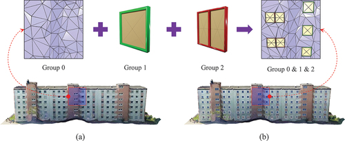
Conversely, the Open Geospatial Consortium has established a clear semantic hierarchy for 3D building models (Gröger and Plümer Citation2012). Beyond differentiating façades and roofs at Level of Detail 2 (LOD2), LOD3 further identifies semantic details within façades, including windows, doors, and balconies. However, mesh models derived from aerial imagery typically lack the necessary geometric structure to depict this level of detail. To address this challenge, we introduce SemanticMesh (), an approach that leverages geometric embedding to efficiently integrate semantic components into photogrammetric mesh models.
Figure 1. SemanticMesh. By fusing semantic components with photogrammetric mesh models (a), we generate textured mesh models enhanced with semantically organized OBJ GROUPS (b).
Undeniably, implementing SemanticMesh is a complex task that involves resolving two key challenges.
Identifying suitable 3D embedded boundaries is hindered by inherent constraints resulting from noise and inconsistent shapes. The façades of building mesh models exhibit either near-planar or non-planar features. The considerable variation in geometric structures among individual components contributes to the complexity of accurately determining the ideal overlapping region within the 3D spatial domain (Kelly et al. Citation2017).
Persisting issues related to the subpar quality of photogrammetric mesh models and the seamless integration of geometric components remain an open problem in computational geometry. Photogrammetric mesh models comprise not only simplexes but also 2-manifolds embedded in the 3D spatial domain. Even when two mesh entities have intersecting regions suitable for fusion, the uneven vertex distribution and presence of poor-quality triangles make the fusion process a complex and substantial endeavor (Furukawa and Hernández Citation2015).
To overcome the challenges previously outlined, SemanticMesh employs a local surface parameterization technique aimed at integrating mesh models. This involves constructing a 3D surface tree, transforming the integration of semantic components with the photogrammetric mesh into a targeted mesh replacement task. By assessing the spatial attributes – position, orientation, and size – of the semantic components, we designate a specific local area on the building’s surface. Utilizing our local surface parameterization approach, we convert this specified area into a 2D mesh. Following this, triangulation is applied within the 2D domain, which is then remapped back into 3D space, facilitating our mesh deformation technique around the 3D boundary. This process achieves a smooth incorporation of the semantic components into the building mesh model, ensuring a coherent and integrated result.
At its essence, this manuscript presents two key innovations: 1) a method for unwrapping local surfaces within photogrammetric mesh models using geodesic vectors, and 2) a strategy for the seamless fusion of semantic components through mesh deformation. The document is systematically structured, starting with Section 2, which reviews pertinent literature. Following this, Section 3.1 offers an in-depth overview of our methodology, and Section 3.2 delves into our technique for local parameterization. Furthermore, Section 3.3 details our approach to semantic enhancement. Section 4 provides a comprehensive analysis of the experimental data and findings. The paper concludes with Section 5, summarizing our research outcomes and implications.
2. Related works
We will conduct a brief review focusing on two aspects most relevant to our research: 1) LOD3 building modeling, and 2) fusion of 3D mesh models.
2.1. LOD3 building modeling
The current work on automatic LOD3 model reconstruction predominantly employs non-end-to-end methods, segmented into multiple stages, notably LOD2 reconstruction and façade modeling (Huang et al. Citation2020; Kelly et al. Citation2017; Verdie, Lafarge, and Alliez Citation2015). Three primary strategies exist for LOD2 model reconstruction: model-driven (Wang, Peethambaran, and Chen Citation2018), data-driven (Haala and Kada Citation2010), and learning-based (Li et al. Citation2022). The model-driven approach often utilizes a library of parametric models, which includes basic building shapes such as flat, gabled, and trapezoidal roofs. This method fits the roof parameters using point cloud data and selects the most suitable model from the library (Lafarge et al. Citation2010). However, the limited diversity in shapes makes the model-driven method challenging to apply to complex buildings and intricate urban environments. In contrast, the data-driven method focuses on reconstructing the topological structure of planes to form a closed geometric building body (Bouzas, Ledoux, and Nan Citation2020) Yet, due to noise, the extraction of line or plane primitives may lack accuracy, leading to incorrectly oriented, extraneous, or missed primitives (Li and Nan Citation2021). The learning-based approach, although innovative, requires specific supporting datasets.
Building on a high-quality LOD2 model, LOD3-level models can be developed by incorporating façade modeling techniques (Hensel, Goebbels, and Kada Citation2019). Façade modeling is generally categorized into data-driven and model-driven approaches (Fan, Wang, and Gong Citation2021; Haala and Kada Citation2010; Wang et al. Citation2024). The data-driven approach involves façade data segmentation using unsupervised clustering, machine learning, or deep learning to identify bounding boxes of façade elements from data sources such as street view images and terrestrial point clouds. The results are refined with 2D layout optimization strategies (Hu et al. Citation2020; Jiang et al. Citation2016; Mathias, Martinović, and Gool Citation2016), followed by mapping between two and three dimensions to embed geometric structures such as windows and doors onto the LOD2 surfaces, thus completing the LOD3 model.
Model-driven façade modeling, leveraging the regularity of building façades, typically uses predefined grammars (Teboul et al. Citation2013) or rules (Fan, Wang, and Gong Citation2021). This method frames façade modeling as a search for combinations from a set of predefined rules and fitting parameters. Ideally, any random combination can lead to a potential façade decomposition, and using stochastic sampling models, such as Markov random fields, and optimizing them can produce final results. However, extensive search spaces can make the optimization process time-consuming or fail to converge. Some studies have investigated learning methods by defining a limited number of common grammars and learning universal grammars from annotated façades and corresponding grammar parsing trees (Dehbi et al. Citation2017; Gadde, Marlet, and Paragios Citation2016). However, the probability models generated from such methods are constrained by the training set and may be challenging to extend to general façades.
In summary, accurately and automatically reconstructing LOD3 models for large-scale urban scenes, incorporating geometry, texture, materials, and semantics, continues to pose a significant challenge. Photogrammetric mesh models are essential data sources for LOD model reconstruction, with current technologies allowing nearly fully automated production using oblique imagery on a large scale. Existing methods (Gao et al. Citation2023) successfully achieve LOD2 semantic level segmentation, differentiating between building façades and roofs. This article will explore data enhancement at the LOD3 semantic level, aiming to distinguish typical objects within façades, and thus provide finer-grained data support, either directly or indirectly, for downstream tasks.
2.2. Fusion of 3D mesh models
We will now embark on related work concerning the seamless fusion of 3D meshes, dividing into two distinct categories: mesh Boolean operations and parameterization-based methodologies. The former further divides into voxel-based and subdivision-based techniques. The voxel-based approach, for example, uses voxels to represent the mesh and achieves fusion through voxel manipulation. Subsequently, it classifies the mesh based on interior and exterior data and extracts the outer surface. Despite the robustness of this approach, the quality of the fusion depends on the granularity of voxel division. Preserving the geometric and topological information of the original mesh at the stitching point remains a challenge, even with high-resolution voxel division (Hu et al. Citation2020; Wang Citation2011; Zhao et al. Citation2011). Therefore, these methodologies are often considered as approximation techniques.
On the other hand, the subdivision-based method leverages Binary Space Partitioning (BSP). In this method, each triangle is treated as an exact plane, and the global or local mesh is represented through BSP trees. Using spatial search strategies such as octrees and k-d trees, it identifies intersecting primitives, such as two intersecting triangles. It then extracts the outer surface using the interior and exterior markers of the leaf nodes (Campen and Kobbelt Citation2010; Nehring-Wirxel, Trettner, and Kobbelt Citation2021; Trettner, Nehring-Wirxel, and Kobbelt Citation2022). Despite several studies implementing numerical computation strategies to mitigate the issue of floating-point rounding (Cherchi et al. Citation2022), accurately obtaining the intersection in 3D space remains a challenge due to the presence of very small, narrow, coplanar, nearly coplanar triangles, or ray collision points near mesh edges (Trettner, Nehring-Wirxel, and Kobbelt Citation2022). Therefore, achieving a balance between the robustness and efficiency of such methods is not an easy task.
Indeed, in the context of a 2-manifold open surface mesh, discrete mathematics lays a solid foundation for a bidirectional correspondence between the 3D mesh and a 2D region (Smith and Schaefer Citation2015). Leveraging this fundamental concept, parameterization methodologies map the 3D mesh onto a plane for 2D triangulation and then reproject it back into the 3D space for mesh fusion (Qian et al. Citation2016; Salval, Keane, and Toal Citation2022; Takayama et al. Citation2011; Zhang et al. Citation2017). However, these existing methods place high demands on the quality of the mesh. For instance, the sampling density of the two meshes should be nearly uniform and substantial, which makes these methods challenging to directly apply to photogrammetric meshes.
Our method centers on a surface modeling strategy designed to integrate semantic components into photogrammetric mesh models seamlessly, preserving the original building’s texture and geometric details. We utilize the OBJ format for mesh models, employing the GROUP keyword to denote semantic elements. Throughout the process of merging geometric components, we dynamically adjust the GROUP attribute. Our approach sets itself apart from conventional mesh fusion methods by specifically requiring the meshes to be 2-manifolds, thus avoiding stringent quality prerequisites.
3. Methods
3.1. Overview and problem setup
3.1.1. Overview of the approach
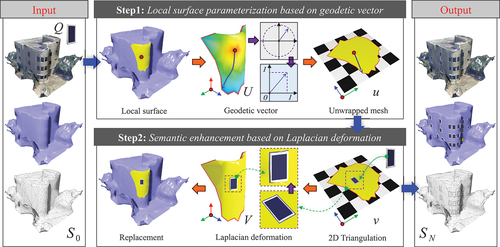
Our workflow, illustrated in , consists of two main stages, adopting a component-by-component fusion approach to respect the unique characteristics of each semantic component, inspired by the surface structure tree model (Schmidt and Singh Citation2008). Initially, we determine the spatial attributes – position, orientation, and size – of the component, followed by the creation of a local surface on the building mesh. Employing geodesic lines from the discrete surface (Crane, Weischedel, and Wardetzky Citation2017), we execute a polar-to-Cartesian coordinate conversion to map the local surface onto a 2D plane. This step facilitates the alignment of the semantic component with the plane, incorporating its edges into the parameterized plane via 2D triangulation. Subsequently, a 2D-to-3D mapping technique identifies the 3D boundary, enabling the reconstruction of the semantic component through Laplacian mesh deformation from this boundary. The process concludes with mesh replacement to integrate the semantic components into the photogrammetric mesh model seamlessly.
Figure 2. Overview of the workflow. The workflow is divided into two primary steps, which are further elaborated in the subsequent sections.
3.1.2. Problem setup
Mesh models and semantic components
. Our focus typically lies on a specific portion of the photogrammetric mesh model, which corresponds to a building referred to as
. Furthermore, we utilize a collection of pre-constructed semantic components, denoted as
, with standardized sizes, as our inputs. To obtain the final components
, we apply a transformation matrix
to
, yielding the equation
. In our previous research (Wang et al. Citation2024), we thoroughly discussed the determination of matrix
. Given that a building consists of multiple components, we sequentially stitched them, resulting in intermediate outcomes
. Both
and
are regarded as 2-manifold meshes, free from topological errors such as self-intersections or stray triangles.
Local supporting patch . Each component
is associated with a local supporting patch
, which is extracted through spatial search in Riemannian space within the photogrammetric mesh models
. The residual portion of
obtained by subtracting
is denoted as
. It is important to note that the boundary of
, referred to as
, precisely aligns with the boundary of
, thus satisfying the condition
.
Local surface parameterization . The photogrammetric mesh model
, the local supporting patch
, and the semantic component
, are all 2-manifolds immersed within a 3D space. However, the direct stitching of these models in 3D space remains an unresolved challenge in the field of computational geometry (Furukawa and Hernández Citation2015). To address this issue, we employ surface parameterization by projecting the meshes into 2D space
, denoted as
. Specifically, the local supporting patch
is parameterized as
. For additional information, please refer to Subsection 3.2, where we provide more detailed explanations. The proposed parameterization method effectively preserves the triangular topology of the meshes between the 3d and 2d spaces, ensuring the consistency of the boundary
.
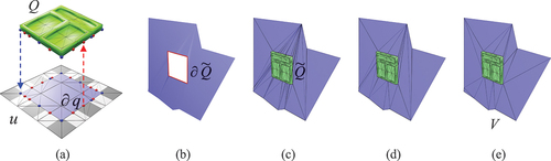
Surface editing . The process of surface editing involves enhancing the local patches denoted as
by fusing semantic components
thereby resulting in the creation of
. It is crucial to maintain the unchanged boundary topology, expressed as
, in order to ensure mesh stitching during subsequent steps. This operation takes place within a 2D space denoted as
, where the boundary
is embedded into
to obtain
. The meshes are then combined using Constrained Triangulation (CT) to produce
, while preserving the outer boundary
. The surface editing process is concluded by applying the warping operation
. Elaborated information can be found in Subsection 3.3.1.
Non-rigid mesh warping . Following the parameterization of mesh models in 2D space, it becomes imperative to reintroduce them into the domain of 3D space. Nonetheless, the rigid assumption often proves inadequate in light of the existence of noise and irregular regions, despite the prevalence of planar regions in architectural structures. In order to tackle this challenge, SemanticMesh exploits non-rigid mesh warping techniques, which exhibit greater resilience toward undesirable flaws and enhance the overall effectiveness of this process. Elaborated information can be found in Subsections 3.3.2 and 3.3.3.
Surface stitching and editing tree. The process of surface stitching entails the direct stitching of the modified local patch
with the original mesh models. To be more precise, the updated mesh model is obtained through the computation
. This direct stitching is made possible by ensuring the preservation of the boundary topology. Furthermore, a tree structure (Schmidt and Singh Citation2008) has been devised to establish connections among all the surface editing operations, as depicted in the equation presented below.
3.2. Local surface parameterization based on geodetic vector
3.2.1. Basic parameterization
Riemannian geometry gives a basic parameterization method based on the geodetic vector. According to a seed point on the 3D surface, the neighborhood of
is mapped to the tangent frame
, for any unit vector
, there exists a geodetic line
, such that
and
, for any point
in the neighborhood of
, the polar coordinate
is mapped to
,
is the geodetic length from
to
,
is the polar angle of
on
, the polar coordinate can be expressed as a Cartesian coordinate by any orthogonal base on
, the 2D vector is called the geodetic vector.
3.2.2. Geodetic vector on discrete surface
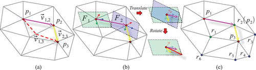
For discrete surface, although there are many methods for calculating the geodetic length (Crane, Weischedel, and Wardetzky Citation2017; Sharp and Crane Citation2020), the corresponding polar angle are still difficult to express effectively. Therefore, we do not directly calculate the polar coordinates from each vertex to the seed point, but use the geodetic vector superposition method (Vaxman et al. Citation2016) for parameterization. In , it is assumed that there are three vertices ,
and
on a 3D mesh surface, where the vectors
and
are known, the goal is to obtain
. Note that the tangent frames of
and
are
and
, as shown in , the rotation matrix from
to
is
, define
Figure 3. Local surface parameterization. By utilizing a vertex on the discrete surface and its adjacent neighborhood (a), we achieved local surface parameterization through a series of steps: (b) transforming the coordinate system, summing vectors, and (c) employing a strategy that includes multiple path weighting.
Therefore, for any vertex , the vertex sequence obtained by a shortest path algorithm is
, and the geodetic vector on each tangent frame is continuously superimposed along the path, then the geodetic vector of
on
can be expressed as
3.2.3. Multi-path weighted strategy
Since the building surface is generally not a smooth surface, there will be obvious cumulative errors directly using the above method, so we introduce a multi-path weighted strategy, as shown in , the one-ring points of are
, where the geodetic vectors of
and
are known, which are the upper neighbor points of
(the rest has no effect on
), denoted as
, then
We consider that the longer the path and the greater the curvature change, the smaller the weight of the path. Denote , which length is
,
is the normal vector of
, denote
, then
is
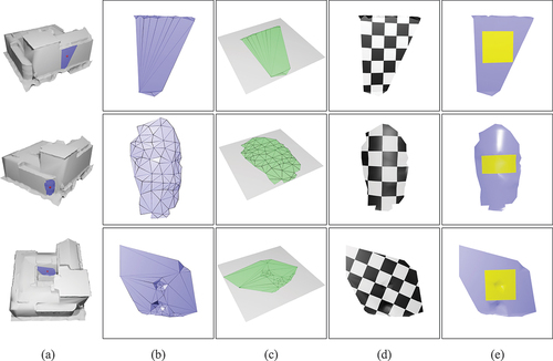
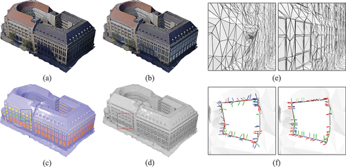
Different from some nonlinear methods using energy functions, we realize the automatic determination of the local surface and complete the parameterization at the same time through a simple linear operation after the seed point and radius are given. The point and radius can be determined adaptively by the pose of . We employed our parameterization techniques on distinct local regions within a shared building model, as show in . Notwithstanding substantial variations in mesh geometry and resolution across these three regions, our methodology exhibits negligible distortion, as evidenced by the preservation of the chessboard texture and accurately embedded yellow rectangles.
Figure 4. Findings of local parameterization. We selected three distinct local surfaces (b) from the same building model (a) to demonstrate the application of the parameterized planar mesh (c), along with its corresponding rendered 3D mesh, which was textured with a chessboard pattern (d). To further enhance precision and visual appeal, a rectangle was incorporated into the planar mesh (c), resulting in a remapped visualization shown in (e).
3.3. Semantic enhancement based on Laplacian deformation
3.3.1. Boundary condition
We will now present the technique of fusing onto
to obtain
. Let us denote the reconstructed semantic component on
as
. Initially, we will describe the method for determining the 3D embedded boundary
. We project the boundary
of the component onto the parameterized mesh
and define the resulting 2D embedded boundary as
. In , we can observe two types of vertices present in
: the blue vertices represent the projected positions of the vertices from
, while the red vertices depict the points of intersection derived from cutting the edges in
. To seamlessly merge
into
, we divide the edges of
based on the distribution ratio of the vertices along
. By utilizing the known 3D coordinates of all points on
, we can determine the 3D coordinates associated with the vertices on
through barycentric interpolation of triangles. Consequently, this process yields the final 3D embedded boundary
illustrated in .
Figure 5. Semantic enhancement via Laplacian deformation: (a) embedding the 2D boundary, (b) calculating the 3D boundary, (c) deforming the component, (d) contracting edges, (e) proceeding with the remeshing process.
3.3.2. Mesh deformation
In the absence of prior knowledge for determining the coordinates of the remaining vertices in reconstructed components beyond the 3D embedded boundary, we resort to a computational geometry technique for mesh deformation to reconstruct the components based on the embedded boundary. We specifically employ Laplacian mesh deformation, which considers rotation invariance. This method unfolds in three primary steps as follows.
Determining the tangent frame. Denote the sets of tangent frames for the vertices on ,
, and
as
,
, and
, respectively. Following the methodology proposed in (Lipman et al. Citation2005), we perform interpolation of the tangent frames
for all vertices within the reconstructed components.
Laplacian coordinate transformation. Rotation invariants, denoted as , are defined as rotation matrices that describe the relationship between two tangent frames. Let
and
denote the Laplacian coordinates of all vertices in
and
, we have
Laplacian mesh deformation. The Laplacian mesh deformation can be expressed by EquationEquation 7(7)
(7) , wherein
represents the Laplacian matrix, and
denotes the ultimate 3D coordinates of all vertices on
. Given that the pose of the embedded boundary is already known, we can readily solve the equation. The resulting solution is depicted in .
3.3.3. Post-processing
It should be noted that when contains large triangles, the projection cutting process can lead to the formation of many narrow triangles, as shown in . This situation may affect the robustness of the fusion operations that follow. To mitigate this, two strategies have been adopted. The first involves edge collapses along the embedded boundary to minimize the presence of nearly parallel edges, with the results shown in . The second strategy employs the remesh algorithm on the one-ring neighborhood around the embedded boundary. Through these approaches, we have created
from the local surface
and an independent component
, as illustrated in .
4. Experimental evaluations and analyses
4.1. Dataset description
To evaluate the effectiveness of our method, we utilized oblique images from three different regions: Shenzhen, Dortmund, and Zeche Zollern. The first dataset was compiled by us, while the latter two are publicly available datasets from (Nex et al. Citation2015). We employed a standard oblique photogrammetric 3D reconstruction pipeline (ContextCapture Citation2023) to generate mesh models for each area. As illustrated in , photogrammetric meshes, unlike those typically used in computational geometry, are characterized by their low quality and irregularity. This is evident first through the non-uniform vertex density, resulting in some nearly planar façades being represented by fewer, larger triangles. Additionally, the façades may not be perfectly planar. Furthermore, these mesh models are significantly affected by noise. The subsequent sections will delve into experimental validation focusing on these specific data characteristics.
Figure 6. Datasets: (a) Shenzhen, (b) Dortmund, (c) Zeche Zollern, (d) façade components.
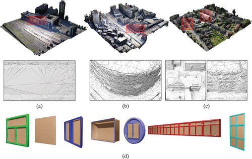
The processed mesh underwent repair for geometric and topological errors through preprocessing techniques, such as hole filling, and the elimination of duplicated vertices, edges, and facets, culminating in a mesh that strictly adheres to 2-manifold criteria (MeshLab Citation2023). Additionally, we crafted various common detailed façade components and cataloged them in a model library (Blender Citation2023). Each component is characterized by an open boundary and semantic labels. The framework for the reconstructed components within the 3D scene, encompassing their position, orientation, and size, was established in our preceding research (Wang et al. Citation2024).
4.2. Evaluation metrics
We denote the original building mesh as , the component mesh as
, and the fused mesh as
. Within
,
belongs to the original building,
to the semantic components, and
to the reference model. The objective of our method is to satisfy several conditions: 1) ensure the geometric quality of
does not degrade significantly compared to
, 2) maintain the integrity of
without damage, 3) achieve high similarity between
and
, 4) keep the data volume of
manageable. To evaluate the effectiveness of our approach, we have adopted three metrics:
In this framework, the condition of component mesh is quantitatively evaluated:
equals 0 if
is damaged and 1 if it remains intact. The metric
represents the average quality (Farin Citation2012) of the mesh
, where
is a floating-point number ranging from 0 to 1. Values closer to 1 denote superior mesh quality. The Hausdorff distance
between the fused mesh
and the reference model
serves as another critical metric (Corsini et al. Citation2007), with smaller values indicating closer similarity and better results. Additionally,
, the number of faces in the mesh, is tracked to ensure that the complexity
remains close to 1, avoiding excessive data volumes. It is worth noting that the experimental area lacks reliable ground truth data, making it impossible to obtain credible façade component-level detailed models through image-based 3D reconstruction methods. Therefore, we established a model using an interactive modeling approach (Blender Citation2023), treating it not as the ground truth but as a reference.
4.3. Qualitative experiment
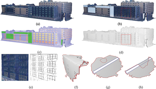
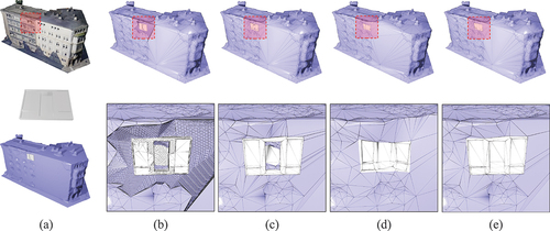
We classify the façades we address into three types: smooth and near-planar, smooth and non-planar, and noisy. display the results for these three surface categories. From , it is clear that our approach minimizes slender triangles. Furthermore, in the area marked by a blue border in , we integrate an elongated component along the sharp edges where the façade intersects with the roof. The resulting local surface, depicted in , is marked by distinct red boundary lines. We juxtapose parameterization with direct planar projection in ), with the component’s boundary highlighted in blue. Direct planar projection results in overlapping faces, complicating the identification of boundary vertices. In contrast, our parameterization technique, even though it may lead to face overlaps near the boundary, does not prevent the calculation of 3D coordinates for boundary vertices, thereby demonstrating superior robustness.
Figure 7. Semantic enhancement for smooth and near-planar façades: (a) input, (b) textured, (c) semantic rendering, (d) mesh, (e) enlarged. Due to potential irregularities in local surfaces (f), embedding the component’s boundary after parameterization (g) exhibits higher robustness compared to directly embedding the boundary in planar projection results (h).
illustrates the outcomes achieved on smooth and non-planar façades. From , it is clear that our approach embeds the component boundaries into the building’s surface, followed by reconstruction based on these boundaries. This enables the fusion of components with diverse shapes. The blue box in highlights the fusion results on the non-planar region, while shows the original input component and its deformed shape. As observed, the deformation of the original component’s boundary, driven by our method, changes the entire component, leading to a more seamless fusion with the building surface.
Figure 8. Semantic enhancement for smooth and non-planar façades: (a) input, (b) textured, (c) semantic rendering, (d) mesh, (e) enlarged. In specific smooth and non-planar regions, the embedded boundaries display distinct curvature. Using our methodology, this deformation is propagated to the entire component (f), leading to a reconstructed component with enhanced conformity to the original building surface.
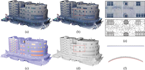
Indeed, our methodology substitutes a specific region within the original building model with components, thereby replacing the noise in that region, as demonstrated in . On the left side, the unaltered mesh of the red box area is shown, and on the right side, the fused result is displayed. However, the embedded boundaries undergo distortion due to inherent noise. Consequently, deforming the components based on the tangent frame of each vertex becomes unsuitable, as illustrated on the left side of . When dealing with façades characterized by significant noise, we replace the tangent frame of the embedded boundary vertices with the component’s frame, as depicted in . This approach results in a seamless fusion of the noisy façade and components.
Figure 9. Semantic enhancement for noisy façades: (a) input, (b) textured, (c) semantic rendering, (d) mesh. Our method replaces the noise on the façade with components (e). However, noise-induced inaccuracies in the tangent frame of the embedded boundaries make it unsuitable for subsequent component deformations. We address this by substituting the tangent frame of the boundaries with the component’s frame (f).
4.4. Comparative experiment
illustrate the comparative results of our technique against traditional approaches: the voxel-based method (Museth et al. Citation2002), the BSP-based methodology (Campen and Kobbelt Citation2010), and the commercial solution Fusion360 (Fusion360 Citation2023), a parameterization-based method for integrating components on three distinct surface typologies. The granularity of voxel subdivision significantly influences fusion results, and accurately delineating embedded boundaries presents a considerable challenge.
BSP-based methodology, though accurate for intersection, has limitations when applied to photogrammetric mesh models. It leads to excessive elongated triangles with large triangles on the façade, hinders direct reconstruction of components from a rigid model on non-planar surfaces, and causes component damage when noise is present on the façade.
On the other hand, Fusion360 does not precisely solve the 3D intersected lines between components and the building surface. It uses the component boundary as a constraint on a parameterized plane, achieving fusion through constrained Delaunay triangulation of the building surface. Although this strategy may yield smooth results on dense and uniformly distributed meshes, it fails to preserve the inherent structural characteristics of the building model, leading to a collapsing effect.
Figure 10. Comparisons of different fusion methods on the smooth and near-planar façade: (a) meshes ,
and
, (b) voxel-based, (c) BSP-based, (d) Fusion360, (e) proposed. The façade, delineated by large triangles, results in degenerate triangles with the BSP-based approach. A sparse number of vertices are at the sharp edge. While Fusion360 maintains vertex positions, it alters the mesh’s topology, erasing key architectural features. Our method addresses these issues.
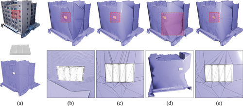
Figure 11. Comparisons of different fusion methods on the smooth and non-planar façade: (a) meshes ,
and
, (b) voxel-based, (c) BSP-based, (d) Fusion360, (e) proposed. Façades often deviate from simple planar configurations. For such structures, creating compatible components tailored to various shapes is essential. A parameterization-based methodology allows using a standardized component to reconstruct geometric structures across uniquely shaped façades. However, preserving the original building’s topological integrity is vital, a principle our method carefully upholds.
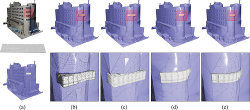
Figure 12. Comparisons of different fusion methods on the noisy façade: (a) meshes ,
and
, (b) voxel-based, (c) BSP-based, (d) Fusion360, (e) proposed. Pronounced perturbations in this model challenge the optimal positioning and orientation of components, making rigid fusion potentially harmful. Fusion360’s attempt to closely conform to the original surface means that if the surface is noisy, the fused components will attach to this distortion, making it unsuitable for photogrammetric mesh models. In contrast, our method replaces this noise with well-defined components, providing an improved solution.
presents the values of the quantitative metrics obtained for three building models using the aforementioned methods, with the optimal values highlighted in light green. It is evident that in some cases, particularly with certain types of surfaces, our method may not perform best for a specific metric. However, overall, our method frequently achieves the most optimal values, especially for metric , where it consistently delivers the best results. One of the primary goals of this paper is to achieve results comparable to manual modeling efficiently.
Table 1. Statistics of various metrics on three types of building façades using different methods.
4.5. Robustness and scalability
To evaluate the robustness of our methodology, we selected two building blocks from the Dortmund and Shenzhen datasets for experiments, as illustrated in . It is crucial to mention that, apart from the essential preprocessing to convert these blocks into strictly 2-manifold surfaces, we did not perform any additional preprocessing on the raw data, including modifications to their geometric structure or topological relationships. Considering the availability of commercial and open-source algorithms for Boolean operations on meshes, we aim to further demonstrate the suitability of our approach for handling photogrammetric mesh models through a detailed comparative analysis.
Figure 13. Experiment using a block from the Dortmund dataset. Figure (a) depicts the final outcome, highlighting red and blue areas that are locally concentrated; these are enlarged in figure (b), shown sequentially from top to bottom. Figure (b) illustrates a progression from left to right, displaying the final model, the original model, and the original mesh. Figures (c) and (d) present the results of implementing Boolean operations and our methodology in the red and blue regions, respectively.
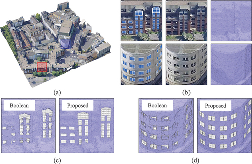
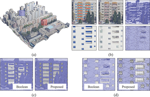
Figure 14. Experiment using a block from the Shenzhen dataset. The final outcome is depicted in figure (a), highlighting locally concentrated areas in red and blue, which are enlarged in figure (b) and shown sequentially from top to bottom. In figure (b), a progression from left to right reveals the final model, original model, and original mesh. Figures (c) and (d) display the results of implementing Boolean operations and our methodology in the red and blue regions, respectively.
The building block in shows a relatively smooth but non-planar topography. Examination of the results reveals that our method, using a pasting approach, has advantages over conventional Boolean operations. Clearly, the primary factor causing the ineffectiveness of Boolean operations in this case is the pose discrepancy inherent in the 3D components.
The building block depicted in features a surface fraught with significant noise, including numerous outward bulges and inward recesses. Before executing Boolean operations, we strategically optimized the layout of the façade, which involved enhancing component thickness and ensuring a specific distance between the geometric center of the components and the building’s outer façade. Despite these adjustments, the direct application of Boolean operations remains unreliable, likely owing to the geometric inconsistencies in photogrammetric meshes and component heterogeneity, complicating a stable layout.
lists the relevant parameters of the façade components for the two building blocks, including the total number and the count of complete components after fusion. The success rate is calculated as the ratio of the number of complete components to the total number. Review of the results indicates that our method demonstrates suitability for photogrammetric mesh models compared to traditional mesh Boolean operations. However, challenges persist even when employing 2D mesh intersection, such as the near overlap of two edges. These challenges hinder our method from achieving perfect fusion of 3D meshes.
Table 2. The relevant parameters of the façade components for the two building blocks.
To evaluate the scalability of the proposed method, we conducted efficiency tests on two individual buildings and two blocks as mentioned. The outcomes are illustrated in , with the horizontal axis in all sub-figures representing the component ID and the vertical axis indicating the time consumed for fusing a single component. provides the number of mesh vertices for both the original models and the final results, alongside the average and total time spent during the fusion process. The findings reveal that the average time for a single fusion operation increases with the data volume of the original model and that the time required for each fusion operation escalates with the growing number of components.
Figure 15. We assess the method’s computational efficiency by progressively fusing components on two individual buildings () and two blocks (). The time taken for each fusion operation was recorded and the results are illustrated in line graphs (a), (b), and (c).
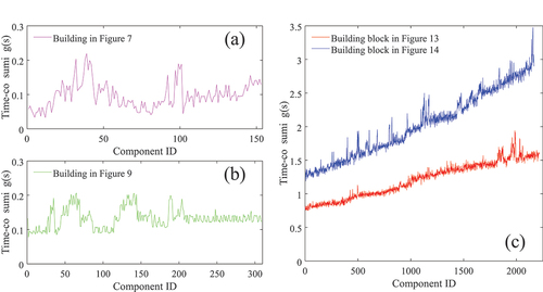
Table 3. Statistics on the number of mesh vertices and the time consumed by fusion operations.
4.6. Discussion and limitations
The photogrammetric mesh presents certain challenges, including irregular geometry and a non-uniform vertex distribution, complicating seamless mesh fusion. However, it also offers inherent advantages, such as ease of acquisition and rich textural details. Consequently, our approach aims to leverage these strengths while recognizing the limitations, utilizing surface modeling techniques to enhance the semantics of mesh models.
In our current work, we are unable to provide texture coordinates for the vertices on the components, leading us to employ pseudo-textures as substitutes for the reconstructed parts. Addressing this issue could involve global texture remapping, which would necessitate reliance on the original oblique images and camera parameters.
5. Conclusions
We exemplify the application of SemanticMesh in the modeling of building façades, which aims to enhance the semantic details of the original model by seamlessly integrating independent semantic components with photogrammetric meshes. For SemanticMesh to operate relatively automatically, efficiently, and robustly in practical applications, two prerequisites are essential: first, the mesh being processed must strictly be a 2-manifold; second, the components and their spatial poses need to be predefined. Regarding the specific implementation of the method, determining the boundary conditions is crucial to ensure a one-to-one correspondence between the vertices on the parameter plane and the boundaries of the components.
Disclosure statement
No potential conflict of interest was reported by the author(s).
Data availability statement
The data that support the findings of this study are available from the corresponding author upon reasonable request.
Additional information
Funding
Notes on contributors
Libin Wang
Libin Wang received the B.S. degree in 2018 and is pursuing the Ph.D. degree with the Faculty of Geosciences and Engineering, Southwest Jiaotong University, Chengdu, China. His research interests include 3D reconstruction, geometry processing.
Han Hu
Han Hu received the B.S. degree in School of Remote Sensing and Information Engineering from Wuhan University, in 2010 and the Ph.D. degree in the State Key Laboratory of Information Engineering in Surveying, Mapping and Remote Sensing from Wuhan University, Wuhan, China, in 2015. He is currently a Professor in the Faculty of Geosciences and Engineering of the Southwest Jiaotong University, Chengdu, China. His current research focuses on 3D reconstruction of our planet earth globally and regionally using datasets collected from the satellites, aircrafts, drones, vehicles, backpacks, and hand-held devices.
Haojia Yu
Haojia Yu received the B.S. degree from the Faculty of Geosciences and Engineering, Southwest Jiaotong University, Chengdu, China, in 2016, where he is pursuing the Ph.D. degree. His research interests include buildings extraction, deep learning, and point cloud semantic segmentation.
Qing Zhu
Qing Zhu received the B.S. and M.S. degrees in aerial photogrammetry from Southwest University, Chengdu, China, in 1986 and 1989, respectively, and the Ph.D. degree in railway engineering from North Jiaotong University, Beijing, in 1995. Since 2014, he has been a Professor and the Director of the Research Committee at the Faculty of Geosciences and Engineering, Southwest Jiaotong University, Chengdu. He also serves as a Visiting Professor with Wuhan University, Central South University, Changsha, China, and Chongqing University, Chongqing, China. His research interests include photogrammetry, GIS, and virtual geographic environments.
References
- Blender. 2023. “Blender 3.5: Viewport Compositor, VDM Sculpting, Built-In Hair Assets, and Much More!” Last accessed on 2023-05-28. https://www.blender.org/.
- Bouzas, V., H. Ledoux, and L. Nan. 2020. “Structure-Aware Building Mesh Polygonization.” Isprs Journal of Photogrammetry & Remote Sensing 167:432–442. https://doi.org/10.1016/j.isprsjprs.2020.07.010.
- Campen, M., and L. Kobbelt. 2010. “Exact and Robust (Self-)Intersections for Polygonal Meshes.” Computer Graphics Forum 29 (2): 397–406. https://doi.org/10.1111/j.1467-8659.2009.01609.x.
- Cherchi, G., F. Pellacini, M. Attene, and M. Livesu. 2022. “Interactive and Robust Mesh Booleans.” ACM Transactions on Graphics 41 (6): 1–14. https://doi.org/10.1145/3550454.3555460.
- ContextCapture. 2023. “ContextCapture: 4D Digital Context for Digital Twins.” Last accessed on 2023-05-28. https://www.bentley.com/software/contextcapture/.
- Corsini, M., E. D. Gelasca, T. Ebrahimi, and M. Barni. 2007. “Watermarked 3-D Mesh Quality Assessment.” IEEE Transactions on Multimedia 9 (2): 247–256. https://doi.org/10.1109/TMM.2006.886261.
- Crane, K., C. Weischedel, and M. Wardetzky. 2017. “The Heat Method for Distance Computation.” Communications of the ACM 60 (11): 90–99. https://doi.org/10.1145/3131280.
- Dehbi, Y., F. Hadiji, G. Gröger, K. Kersting, and L. Plümer. 2017. “Statistical Relational Learning of Grammar Rules for 3D Building Reconstruction.” Transactions in GIS 21 (1): 134–150. https://doi.org/10.1111/tgis.12200.
- Fan, H., Y. Wang, and J. Gong. 2021. “Layout Graph Model for Semantic façade Reconstruction Using Laser Point Clouds.” Geo-Spatial Information Science 24 (3): 403–421. https://doi.org/10.1080/10095020.2021.1922316.
- Farin, G. 2012. “Shape Measures for Triangles.” IEEE Transactions on Visualization and Computer Graphics 18 (1): 43–46. https://doi.org/10.1109/TVCG.2010.256.
- Furukawa, Y., and C. Hernández. 2015. “Multi-View Stereo: A Tutorial.” Foundations and trends® in Computer Graphics and Vision 9 (1–2): 1–148. https://doi.org/10.1561/0600000052.
- Fusion360. 2023. “Fusion 360: More Than CAD, it’s the Future of Design and Manufacturing.” Last accessed on 2023-05-28. https://www.autodesk.com/products/fusion-360/overview.
- Gadde, R., R. Marlet, and N. Paragios. 2016. “Learning Grammars for Architecture-Specific Facade Parsing.” International Journal of Computer Vision 117 (3): 290–316. https://doi.org/10.1007/s11263-016-0887-4.
- Gao, W., L. Nan, B. Boom, and H. Ledoux. 2023. “PSSNet: Planarity-Sensible Semantic Segmentation of Large-Scale Urban Meshes.” Isprs Journal of Photogrammetry & Remote Sensing 196:32–44. https://doi.org/10.1016/j.isprsjprs.2022.12.020.
- Google. 2023. “Google Earth.” Last accessed on 2023-05-28. https://earth.google.com/.
- Gröger, G., and L. Plümer. 2012. “CityGML – Interoperable Semantic 3D City Models.” Isprs Journal of Photogrammetry & Remote Sensing 71:12–33. https://doi.org/10.1016/j.isprsjprs.2012.04.004.
- Haala, N., and M. Kada. 2010. “An Update on Automatic 3D Building Reconstruction.” Isprs Journal of Photogrammetry & Remote Sensing 65 (6): 570–580. https://doi.org/10.1016/j.isprsjprs.2010.09.006.
- Hensel, S., S. Goebbels, and M. Kada. 2019. “Facade Reconstruction for Textured Lod2 Citygml Models Based on Deep Learning and Mixed Integer Linear Programming.” ISPRS Annals of the Photogrammetry, Remote Sensing & Spatial Information Sciences IV-2 (W5): 37–44. https://doi.org/10.5194/isprs-annals-IV-2-W5-37-2019.
- Hobeika, N., L. van Rijssel, M. Prusti, C. Dinklo, D. Giannelli, B. Dukai, A. Kok, R. van Loon, R. Nota, and J. Stoter. 2023. “Automated Noise Modelling Using a Triangulated Terrain Model.” Geo-Spatial Information Science. 1–21. https://doi.org/10.1080/10095020.2023.2270520.
- Hu, H., L. Wang, M. Zhang, Y. Ding, and Q. Zhu. 2020. “Fast and Regularized Reconstruction of Building Faã‡ades from Street-View Images using Binary Integer Programming.” ISPRS Annals of the Photogrammetry, Remote Sensing & Spatial Information Sciences V-2-2020:365–371. https://doi.org/10.5194/isprs-annals-V-2-2020-365-2020.
- Hu, Y., T. Schneider, B. Wang, and D. Zorin. 2020. “Fast Tetrahedral Meshing in the Wild.” ACM Transactions on Graphics 39 (6): 1–16. https://doi.org/10.1145/3386569.339238510.1145/3386569.3392385.
- Huang, H., M. Michelini, M. Schmitz, L. Roth, and H. Mayer. 2020. “Lod3 Building Reconstruction from Multi-Source Images.” International Archives of the Photogrammetry, Remote Sensing and Spatial Information Sciences XLIII-B2-2020:427–434. https://doi.org/10.5194/isprs-archives-XLIII-B2-2020-427-2020.
- Jiang, H., L. Nan, D. Yan, W. Dong, X. Zhang, and P. Wonka. 2016. “Automatic Constraint Detection for 2D Layout Regularization.” IEEE Transactions on Visualization and Computer Graphics 22 (8): 1933–1944. https://doi.org/10.1109/TVCG.2015.2480059.
- Kelly, T., J. Femiani, P. Wonka, and N. J. Mitra. 2017. “BigSUR: Large-Scale Structured Urban Reconstruction.” ACM Transactions on Graphics 36 (6): 1–16. https://doi.org/10.1145/3130800.3130823.
- Lafarge, F., X. Descombes, J. Zerubia, and M. Pierrot-Deseilligny. 2010. “Structural Approach for Building Reconstruction from a Single DSM.” IEEE Transactions on Pattern Analysis & Machine Intelligence 32 (1): 135–147. https://doi.org/10.1109/TPAMI.2008.281.
- Li, L., N. Song, F. Sun, X. Liu, R. Wang, J. Yao, and S. Cao. 2022. “Point2Roof: End-To-End 3D Building Roof Modeling from Airborne LiDAR Point Clouds.” Isprs Journal of Photogrammetry & Remote Sensing 193:17–28. https://doi.org/10.1016/j.isprsjprs.2022.08.027.
- Li, M., and L. Nan. 2021. “Feature-Preserving 3D Mesh Simplification for Urban Buildings.” Isprs Journal of Photogrammetry & Remote Sensing 173:135–150. https://doi.org/10.1016/j.isprsjprs.2021.01.006.
- Lipman, Y., O. Sorkine, D. Levin, and D. Cohen-Or. 2005. “Linear Rotation-Invariant Coordinates for Meshes.” ACM Transactions on Graphics 24 (3): 479–487. https://doi.org/10.1145/1073204.1073217.
- Liu, X., X. Zhu, Y. Zhang, S. Wang, and C. Jia. 2023. “Generation of Concise 3D Building Model from Dense Meshes by Extracting and Completing Planar Primitives.” Photogrammetric Record 38 (181): 22–46. https://doi.org/10.1111/phor.12438.
- Mathias, M., A. Martinović, and L. Gool. 2016. “ATLAS: A Three-Layered Approach to Facade Parsing.” International Journal of Computer Vision 118 (1): 22–48. https://doi.org/10.1007/s11263-015-0868-z.
- MeshLab. 2023. “MeshLab: The Open Source System for Processing and Editing 3D Triangular Meshes.” Last accessed on 2023-05-28. https://www.meshlab.net/.
- Museth, K., D. E. Breen, R. T. Whitaker, and A. H. Barr. 2002. “Level Set Surface Editing Operators.” ACM Transactions on Graphics 21 (3): 330–338. https://doi.org/10.1145/566654.566585.
- Nehring-Wirxel, J., P. Trettner, and L. Kobbelt. 2021. “Fast Exact Booleans for Iterated CSG Using Octree-Embedded BSPs.” Computer-Aided Design 135:103015. https://doi.org/10.1016/j.cad.2021.103015.
- Nex, F., M. Gerke, F. Remondino, H.-J. Przybilla, M. Bäumker, and A. Zurhorst. 2015. “ISPRS Benchmark for MULTI-Platform Photogrammetry.” ISPRS Annals of the Photogrammetry, Remote Sensing & Spatial Information Sciences II-3 (W4): 135–142. https://doi.org/10.5194/isprsannals-II-3-W4-135-2015.
- Qian, G., M. Tang, R. Tong, X. Zhang, and R. Pan. 2016. “Interactive Mesh Cloning Driven by Boundary Loop.” The Visual Computer: International Journal of Computer Graphics 32 (4): 513–521. https://doi.org/10.1007/s00371-015-1085-z.
- Salval, H., A. Keane, and D. Toal. 2022. “Multiresolution Surface Blending for Detail Reconstruction.” Graphics and Visual Computing 6:200043. https://doi.org/10.1016/j.gvc.2022.200043.
- Schmidt, R., and K. Singh. 2008. “Sketch-Based Procedural Surface Modeling and Compositing Using Surface Trees.” Computer Graphics Forum 27 (2): 321–330. https://doi.org/10.1111/j.1467-8659.2008.01129.x.
- Sharp, N., and K. Crane. 2020. “You Can Find Geodesic Paths in Triangle Meshes by Just Flipping Edges.” ACM Transactions on Graphics 39 (6): 1–15. https://doi.org/10.1145/3414685.3417839.
- Smith, J., and S. Schaefer. 2015. “Bijective Parameterization with Free Boundaries.” ACM Transactions on Graphics 34 (4): 1–9. https://doi.org/10.1145/2766947.
- Takayama, K., R. Schmidt, K. Singh, T. Igarashi, T. Boubekeur, and O. Sorkine. 2011. “GeoBrush: Interactive Mesh Geometry Cloning.” Computer Graphics Forum 30 (2): 613–622. https://doi.org/10.1111/j.1467-8659.2011.01883.x.
- Teboul, O., I. Kokkinos, L. Simon, P. Koutsourakis, and N. Paragios. 2013. “Parsing Facades with Shape Grammars and Reinforcement Learning.” IEEE Transactions on Pattern Analysis & Machine Intelligence 35 (7): 1744–1756. https://doi.org/10.1109/TPAMI.2012.252.
- Toschi, I., M. M. Ramos, E. Nocerino, F. Menna, F. Remondino, K. Moe, D. Poli, K. Legat, and F. Fassi. 2017. “Oblique Photogrammetry Supporting 3D Urban Reconstruction of Complex Scenarios.” International Archives of the Photogrammetry, Remote Sensing and Spatial Information Sciences XLII-1 (W1): 519–526. https://doi.org/10.5194/isprs-archives-XLII-1-W1-519-2017.
- Trettner, P., J. Nehring-Wirxel, and L. Kobbelt. 2022. “EMBER: Exact Mesh Booleans via Efficient & Robust Local Arrangements.” ACM Transactions on Graphics 41 (4): 1–15. https://doi.org/10.1145/3528223.3530181.
- Vaxman, A., M. Campen, O. Diamanti, D. Panozzo, D. Bommes, K. Hildebrandt, and M. Ben-Chen. 2016. “Directional Field Synthesis, Design, and Processing.” Computer Graphics Forum 35 (2): 545–572. https://doi.org/10.1111/cgf.12864.
- Verdie, Y., F. Lafarge, and P. Alliez. 2015. “LOD Generation for Urban Scenes.” ACM Transactions on Graphics 34 (3): 1–14. https://doi.org/10.1145/2732527.
- Wang, C. C. L. 2011. “Approximate Boolean Operations on Large Polyhedral Solids with Partial Mesh Reconstruction.” IEEE Transactions on Visualization and Computer Graphics 17 (6): 836–849. https://doi.org/10.1109/TVCG.2010.106.
- Wang, L., H. Hu, Q. Shang, H. Zeng, and Q. Zhu. 2024. “StructuredMesh: 3-D Structured Optimization of Façade Components on Photogrammetric Mesh Models Using Binary Integer Programming.” IEEE Transactions on Geoscience & Remote Sensing 62:1–12. https://doi.org/10.1109/TGRS.2023.3348492.
- Wang, R., J. Peethambaran, and D. Chen. 2018. “LiDAR Point Clouds to 3-D Urban Models: A Review.” IEEE Journal of Selected Topics in Applied Earth Observations & Remote Sensing 11 (2): 606–627. https://doi.org/10.1109/JSTARS.2017.2781132.
- Xue, F., L. Wu, and W. Lu. 2021. “Semantic Enrichment of Building and City Information Models: A ten-Year Review.” Advanced Engineering Informatics 47:101245. https://doi.org/10.1016/j.aei.2020.101245.
- Zhang, D., X. Wang, J. Hu, and H. Qin. 2017. “Interactive Modeling of Complex Geometric Details Based on Empirical Mode Decomposition for Multi-Scale 3D Shapes.” Computer-Aided Design 87:1–10. https://doi.org/10.1016/j.cad.2017.02.003.
- Zhang, X., Z. Hu, Q. Hu, J. Zhao, M. Ai, P. P. Zhao, J. Li , X. Zhou, and Z. Chen. 2024. “A 3D Urban Scene Reconstruction Enhancement Approach Based on Adaptive Viewpoint Selection of Panoramic Videos.” Photogrammetric Record 39 (185): 7–35. https://doi.org/10.1111/phor.12467.
- Zhao, H., C. C. L. Wang, Y. Chen, and X. Jin. 2011. “Parallel and Efficient Boolean on Polygonal Solids.” The Visual Computer: International Journal of Computer Graphics 27 (6–8): 507–517. https://doi.org/10.1007/s00371-011-0571-1.