
Abstract
The Green Energy Mill (GEM) tower is the first mobile hybrid unit of its kind to supply renewable energy to festivals. The energy that the hybrid unit generates from wind and solar resources is stored in a Battery Energy Storage System (BESS) until needed. The hybrid unit is both foldable and transportable and can be stored on site in two twenty-foot equivalent unit (TEU) shipping containers. It also has a transportable foundation that can be installed on various types of surface with no need for earthworks. This study will be focused on the following four main aspects of the design and the construction of the hybrid unit (a) parametric optimization study; (b) unit stability; (c) foundation; and, (d) installation and transportation. The GEM tower has already been installed at several locations and technical aspects of the hybrid unit are reported in this paper, providing useful knowledge for future structures with similar characteristics.
Introduction
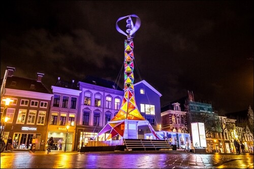
Climate change is now an ever-more widely accepted reality and all industries must take action to minimize its severe consequences. Hence, festivals across Europe are seeking innovative ways of reducing the CO2 emissions of their events and strive to raise awareness of environmental issues. However, diesel generators continue to be widely used to meet the energy demands at many festivals. These generators have several drawbacks such as noise, fumes, and significant CO2 emissions. The Green Energy Mill (GEM) tower () is an initiative to provide renewable energy to festivals.Citation1 It was developed by the Eindhoven University of Technology (TU/e) in collaboration with PowerVIBES consortium partners from both the energy and festival sectors. The hybrid unit incorporates a Vertical Axis Wind Turbine (VAWT) that can generate wind power, and with semi rigid solar panels and Luminescent Solar Concentrator (LSC) panels, powered by both direct and diffuse sunlight, that can generate solar power. The hybrid unit stores the surplus energy in a Battery Energy Storage System (BESS) for subsequent supply when required. Additionally, the GEM tower is transportable in TEU containers and it can be installed at various locations with no need for earthworks. At the base of the unit, festival visitors are informed of the importance of using sustainable energies. The aim is therefore to minimize the use of diesel generators and to instil environmental awareness among the festival audience, thus contributing to climate change mitigation.
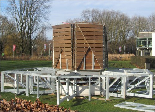
Fig. 1: The GEM Tower installed at the Vismarkt in Groningen (Eurosonic Noorderslag 2020) (source: Jorn Baars)
The GEM Tower
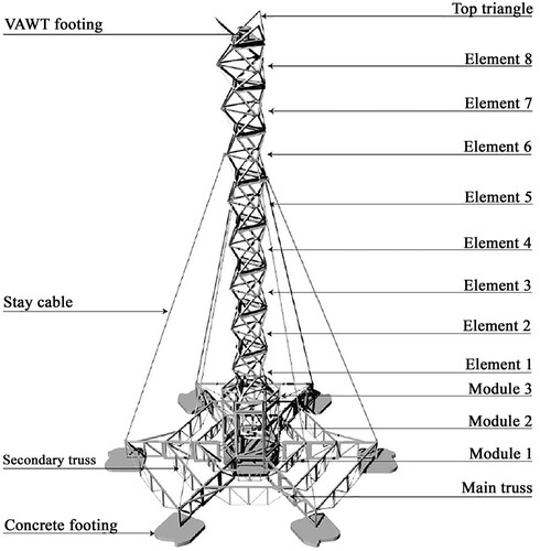
The GEM Tower is a 17.7-meter-high steel-frame construction (), which consists of trusses at the base, three modules, eight foldable elements, three top triangles and the footing of a 4.3-meter-high VAWT. Six stay cables are secured to the hybrid unit at a height 13 metres and to each end of the main (radial) trusses. The main trusses rest on six reinforced-concrete footings, which are covered by a wooden platform at a height of one metre. There are three benches that enclose each side and three stairways for access to the platform from the ground. In addition, colourful PVC canvases that covers part of the structure gives the impression of a unified design ().
Fig. 2: Steel structure of the Green Energy Mill towerCitation3
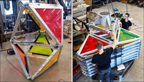
Each element has eight triangular frames and eighteen hinges (a). Some of the triangle frames are fitted with LSC panels, while others are fully open, so that the wind can pass through them. Most of the hinges are linear which facilitated their design and construction. As suitable examples were not found on the market, the technical team designed, tested, and built each of the hinges. The elements can be folded, one on top of another, minimizing storage space in the TEU container. The footing of the VAWT is installed over the last module (8) (b). The two last elements (7 and 8) are not completely unfolded and the triangles are installed at the top to follow the curved line of the design that is enhanced when the canvas is installed ().
Fig. 3 (a). Element with Luminescent Solar Collectors. (b). Fastening the footing of turbine over the folded elements at Eindhoven University of Technology (source: Bart van Overbeeke)
Parametric Study
A parametric study of the elements of the unit was performed to analyse some design options before calculating the structure in detail. The main objectives of the parametric study were to visualize the influence of the stay cables on the weight of the hybrid unit, thus improving stability and portability, always complying within a set deformation limit, and, at the same time, to analyse the best position of the stay cables to reduce the weight of the hybrid unit.Citation2–4 The height of the hybrid unit was set at 20 metres and exposure to wind forces of Vref ≤ 28 m/s was assumed. The data on wind force was retrieved from NEN-EN 13782.Citation5 Wind and VAWT loads were treated as point forces at the nodes of each element (a). The structure was optimized with the 3D modeller Rhino 5 that incorporates the graphical algorithm editor Grasshopper v.0.9.0076 and the parametric structural engineering tool Karamba3D.Citation6 The algorithms used were according to Eurocode 3Citation7 for steel structures. The 3D modeller was first used to model the loads on the hybrid unit, setting a deformation limit of 250 mm. The cross sections of the elements were then optimized. Finally, the weight of the unit was determined to meet the initial deformation requirement.
Fig. 4: (a) 3D model of the structural analysis with three stay-cables; (b) uniform cross-sections; (c) non-uniform cross-sections; (d) variables of the cable analysis.Citation2,Citation3 H = Height; B = Base width
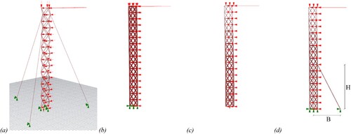
Cross-sectional optimization of the elements followed three steps. The steel cross sections were considered uniform, calculating the weight of the unit at 4310 kg (b). In a second step, the sections were considered non-uniform, thereby reducing the weight by 26% to 3200 kg (c). In a third step, three stay cables were installed, and the most favourable positions were studied. The cables were considered under tension, because Karamba3D can only consider either compression or tension. They were all of the same length, placed at the same distance from each other and connected at the midpoint of the height of each element. The variables in this study were the height, and the width of the base (d). The height was calculated as the perpendicular distance between the midpoint of the height and the base of the element. The width of the base was equal to the distance between the centre of the structure and the point where the cable was connected to the base. This distance determines the diameter of the platform where the end of each stay cable is connected to the main truss.
shows the reductions in the weight of the structure depending on the width and the height of the cable in the x-direction. For the sake of simplicity, the results of the y-direction are not shown, because they showed a similar trend to the x-direction. As can be seen, there was practically no optimization of the weight of the structure at under 4 metres in height. However, the optimization was significant at heights between 10 and 14 metres for most widths. Additionally, the larger the base width, the greater the reduction in weight. The lowest optimization of weight was modelled with the cable connection at around 13 metres in height and secured at 7 metres from the structure. After the third step, the structure was optimized at 1000 kg, a reduction of 77% in weight compared to the initial optimization (b).
Fig. 5: Weight of the structure in relation to the height and base width of the cable (Wind in x-dir)Citation2,Citation3
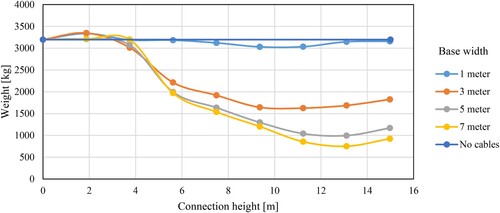
The base width selected for the GEM tower was 5 metres, because it was thought convenient to narrow the platform and the weight remained similar to the best option (7 m). The PowerVIBES partners advised against a larger base, because it would occupy more rental space. Additionally, finding a location for the installation of a larger sized base could be difficult, and the transportation of the hybrid unit might otherwise require more than two TEU containers. The cables were finally connected to the sixth element at a height of approximately 13 metres following the results of the optimization. The sections were finally designed and built uniform, as non-uniform sections, even though they might have reduced the overall weight of the unit, were considered impractical and too expensive to build, due to their non-standard sizes.
Design for Stability
The static analysis of the frame was performed on a 3D model with finite element software SCIA engineerCitation8 and Axis VMCitation9 complying with EurocodeCitation7, NEN-EN 13782Citation5 and Guidelines for Structural Safety at Events.Citation10 It was designed for a terrain category II and a wind force of level 8 on the Beaufort scale (worst case scenario), which is in line with the usual practice of festival structures. The calculation includes a second-order analysis, taking into account the influence of the deformation of the structure, and a global eccentricity of 5 mm/m (ϕ = 1/ 200) in both X and Y directions. Moreover, an eigenfrequency analysis was conducted in Axis VM that validated the eigenfrequency value threshold set at 2.5 Hz after consulting the structural advisors.
The hybrid unit weighs around 22 tons including ballast. Most of the loads are located at the base of the hybrid unit to provide stability (), which consists of a 90-kWh lead-acid gel Battery Energy Storage System (BESS) (3000 kg), a module (module 1) filled with 1 m3 of concrete, 1000 kg of steel, and six peripheral footings (600 kg each). The peripheral footings support the trusses and provide extra stability, as the concrete footings provide a relatively larger arm with respect to the rotation axis. The peripheral footings are connected to modules 1 and 2 by six main (radial) trusses. These main trusses consist of three elements for transport reasons. Each pair of opposing main trusses along with modules 1 and 2 function as a large truss beam. This arrangement is due to the truss-module connections and the frame configuration of modules 1 and 2. When the wind exerts a load, one concrete footing of the large truss beam is under compression. The opposite footing, on the other side of the truss beam acts as counter weight. The footing that is under compression can therefore withstand 40 kN/m2 according to the design calculations, which complies with the regulatory threshold of 80 kN/m2 below which no geotechnical study is required.Citation10 However, the calculation of compression in the footings must be verified at each location because wind forces and ground resistances will vary from one site to another.
Fig. 6: Module 1 (filled with 1 m3 of concrete and 1000 kg of steel); Module 2 (with a 3000 kg- BESS), and some of the main and secondary trusses previously installed. Platform panels are folded over module 2
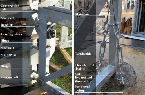
The main trusses are connected with module 1 and 2 using two hinges, two bolts, and a bracket profile (a). The lower and the upper bolts of the truss work under tension and compression, respectively. Shear force is addressed by two bracket profiles, one connected to module 2, and another connected to the main truss, the other way around. The bracket profile is connected to module 2 and not to module 1, because it was not levelled. The hybrid unit was levelled over module 1 with steel levelling plates (a). Moreover, the design height of each truss at the edge of the platform is slightly lower, because the bending moment at the edges is lower. This arrangement also facilitated the installation of the connection between the footings and the main trusses. The compressive force of the structure is transferred to the footing by means of adjustable threaded rods with nuts, installed at the end of the main trusses and positioned at the centre of the footing. Tension force is transferred from the footings to the main trusses with eye nuts, threaded rods, hoisting rings, turnbuckles and steel cables (b).
Fig. 7: (a) Connection of the main truss with module 1 and module 2; (b) tension mechanism between the main truss and the peripheral footing
Foundation
The foundation consists of Module 1 and six peripheral footings, which were prefabricated at the TU/e. Module 1 is a steel frame filled with concrete and has minimal reinforcement, because it simply serves as a dead weight. The peripheral footings support the platform and act as a counterweight and are shaped to fit between the stairways and the benches. They were reinforced to resist the point load from the trusses. The reinforcement was placed at mid-height and consisted of ⌀8-150 steel mesh laid across the entire surface and 3 ⌀10 bars at the centre in the longitudinal direction. In addition, several anchor sockets were installed in the centre and on one side of the footing to facilitate handling and installation. Moreover, footings are stackable one on top of the other to optimize storage space within the TEU container.
Installation and Transportation
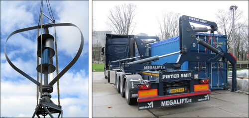
Since the first deployment of the hybrid unit at the Pukkelpop Festival 2019 (Belgium), installation and transportation have been improved at all locations. The unit was installed at the Pukkelpop Festival within five days, while at the most recent location, Circuit Zandvoort October 2020 (The Netherlands), only one day was needed. The VAWT can be installed when the elements are still folded without the need for an aerial work platform. The modules are deployed with a specially designed lifting frame attached to the crane, so as not to damage the VAWT blades, as shown in (a). In addition, space is left around the unit to ensure the safety of spectators at the event in case of extreme weather such as thunderstorms. In this case, which is usually known in advance, the hybrid unit would also be lowered to ensure structural stability. Furthermore, the hybrid unit occupies a privileged place at outdoor events, as it is highly visible and can easily serve as a meeting point. Two conventional trucks were used to transport the unit to the festival in Belgium, and the containers were unloaded from the truck with a self-propelled crane. However, all components of the hybrid unit currently fit into two TEU containers that are transported by a single biodiesel-fuelled side-loader truck. Once at the site, the TEU containers are unloaded by the crane on the side-loader truck (b), although an independent crane is required to deploy the hybrid unit. The hybrid unit can be transported from one outdoor event to another with no need for it to be stored at a central location. Additionally, the TEU containers can be locked and stored at a new location for several days. These improvements to the installation and transportation of the GEM tower significantly reduce associated costs, time and environmental impact.
Fig. 8: (a) Lifting frame attached to the crane to unfold the elements; (b) the unit is transported in two containers on a single side-loader truck
Concluding Remarks
An overview of the design and construction of the first hybrid unit that supplies renewable energy to festivals has been presented. The GEM tower has been designed to generate energy from the wind with a Vertical Axis Wind Turbine and from the sun with semi rigid solar panels and Luminescent Solar Concentrator panels, for storage the surplus in a Battery Energy Storage System until required. It is transportable in two TEU containers. Four main aspects have been addressed: (a) parametric optimization study; (b) unit stability; (c) foundation; and, (d) installation and transportation. The hybrid unit has been installed at several locations in northern Europe and will be in continual use over coming years. The design process, its continual optimization, and the technical solutions have provided useful knowledge for future versions of the same structure and others that may have similar characteristics.
Acknowledgements
This research has been accomplished thanks the support from Interreg Europe North-West Europe (PowerVIVES project – NWE539), the Eindhoven University of Technology, IBIS Power, Double 2, Pukkelpop 2019, Offgrid energy, Dour, RPS, ESNS, FLEXOTELS and ZAP. We gratefully also acknowledge the help provided by M.C.J. (Moniek) Sanders, Julia Schönwälder, Hèrm Hofmeyer, B. (Bas) Geenen and C.J.S. (Sjoerd) Groeneveld.
References
- Pujadas, E et al. GEM tower. CHEPOS 34, 2019.
- Lenaers, WJH. Project progress report: Q4-2018, 2018. Available at: https://research.tue.nl/nl/publications/project-progress-report-q4-2018. Accessed: 29th September 2020.
- Lenaers, WJH . GEM-tower: structural engineering and design, 2020. Available at: https://research.tue.nl/en/publications/gem-tower-structural-engineering-and-design. Accessed: 29th September 2020.
- Lenaers, WJH. Project progress report: Q3-2018, 2018. Available at: https://research.tue.nl/nl/publications/project-progress-report-q3-2018. Accessed: 29th September 2020.
- NEN-EN 13782. Temporary structures. Tents. Safety. Nederlands Normalisatie Instituut, 2015.
- Karamba3D, 2020. Available at: https://www.karamba3d.com/. Accessed: 29th September 2020.
- Eurocodes. Nederlands Normalisatie-instituut, 2019. Available at: https://www.nen.nl/NEN-Shop/Eurocodes.htm. Accessed: 29th September 2020.
- SCIA engineer, 2020. Available at: https://www.scia.net/en. Accessed: 29th September 2020.
- AxisVM, 2020. Available at: https://axisvm.eu/index.html. Accessed: 29th September 2020.
- COBc. Richtlijn voor Constructieve Toetsingscriteria bij een aanvraag voor een Evenementenvergunning, 2018.