
 ?Mathematical formulae have been encoded as MathML and are displayed in this HTML version using MathJax in order to improve their display. Uncheck the box to turn MathJax off. This feature requires Javascript. Click on a formula to zoom.
Abstract
In bridge planning, the successful translation of the many conditioning factors into a solution that meets all safety requirements while also addressing considerations such as economy and elegance is essentially a matter of conceptual design. Despite the utmost importance of that stage, which in addition to an intuitive understanding of load-bearing mechanisms calls for imagination and a sense of form and beauty, creative conceptual thinking is systematically underestimated both in engineering training and everyday practice. The resulting impoverishment of the profession stems not only from growing, need-driven and hardly reversible specialisation, but also from inexorably extensive and opaque standardisation and control. The rules for ensuring robustness reflect the increasing complexity and opacity characterising structural design codes. While the practical importance of designing and building robust structures is universally acknowledged, the codes presently in place are often vague or confusing. Cross-referencing, in turn, may lead to loops around rules that, confounding engineers, are counterproductive. At the same time, however, that lack of clarity may afford opportunities for innovative solutions by building items that ensure robustness into the conceptual design of a structure. This paper proposes an operational design process that deals appropriately with all factors of structural performance, including robustness, without compromising bridge economy or elegance. That process, which combines a number of robustness strategies, including risk-based considerations, is illustrated with a case study of a proposal submitted to a design competition for a viaduct.
Introduction
Once the general infrastructure requirements (e.g. layout of the road; clearance profile; etc.) have been established for a bridge needed to span an obstacle, the basic objectives to be pursued in structural design are safety, service performance, economy and elegance. Many key factors in bridge design are governed by construction site-related, geometric, functional and constructional constraints. Conceptual design merits considerable thought if the many conditioning factors involved are to be moulded into a solution compliant with all requirements.
By definition, structural safety and serviceability are ensured when codes and standards are duly followed and are therefore primarily dependent upon engineers’ analytical skills. Economy and elegance, on the other hand, are subject to no hard-and-fast rules. Although guidelines have been proposed to combine mechanics and aesthetics in bridge design based on the analysis of acknowledged masterpieces to formally link bridge engineering and art,Citation1 their routine application does not guarantee satisfactory results. Designer imagination, intuition and sense of form and beauty are also imperative.Citation2
Like other disciplines, structural engineering is characterised by increasing specialisation, driven by the growing complexity of analytical and verification methods, materials technology and construction procedures. Such specialisation comes at the expense of conceptual design training in engineering schools and consequently of structural engineers’ creativity.Citation3 The insufficient importance attributed to conceptual and creative thinking, both in engineering training and in practice, and the concomitant impoverishment of the profession are also a result of increasingly extensive and opaque standardisation and control systems.
The rules on robustness presently in place denote the increasing complexity of structural design codes. Many modern codes such as the EurocodeCitation4 stipulate, for instance, that the consequences of structural damage attributable to an unforeseen adverse event must not be disproportionate to the respective cause. Although that feature is generally acknowledged to be justified, the provisions of structural codes and standards intended to ensure its application are often vague.Citation5 One key problem in this regard is the absence of any general design philosophy around robustness. The measures laid out in codes to reduce damage caused by unidentified hazardous events are mainly confined to a statement of general principles. Indeed, the Eurocode provisions in this regard have not been substantiated by comparison to the conditions prevailing in cases of structural collapse due to the complexities involved and have been reported to be subject to major shortcomings.Citation5 In light of such considerations, today’s robustness rules may not only be inapplicable to real-life cases, but may also spawn unsafe design, even where each separate member in a given structural system complies with reliability standards.Citation6 Inasmuch as such rules provide designers with little useful guidance,Citation5 they may actually be counterproductive.
Given that the possible propagation of damage ensuing from local failure in a load-bearing system depends heavily on the underlying structural concept, conceptual design is of utmost importance to ensure a structure will be sufficiently robust, as well as compliant with all other design goals. Robustness must consequently be addressed early in the design process and more specifically in the conceptual design stage.
The section of the paper entitled ‘Current situation’, on the most common strategies for designing robust structures and their associated problems, is the point of departure for an operational design proposal with which to suitably address all the factors involved in structural performance, including disproportionate collapse issues, without compromising the economy and elegance of a bridge. The section entitled ‘Structural design’ addresses a number of basic principles and ideas that inform conceptual design, here deemed to be a crucial stage in the overall process. Application of the proposal to a real-life design situation is described in the section on the ‘Hauterive Viaduct’, a steel and concrete composite girder bridge with an extradosed main span and flexible support conditions. Practical rules for checking robustness consistent with the proposed strategies are suggested on the grounds of that case study.
Current Situation
Structural Behaviour and Reliability
The reliability of a structure built for a specific purpose and subject to singular conditions depends on a host of inherent features, including the structural system and its ductile or brittle behaviour in particular. Applying the principles of system reliability,Citation7 the significance of those two features can be illustrated by comparing load-bearing systems that while equivalent comprise members representing different behaviour patterns: statically determinate members; statically indeterminate members exhibiting brittle behaviour; or statically indeterminate members characterised by ductile behaviour.Citation8 Consistent design rules such as laid down in the Eurocodes would provide for strict compliance by all three systems with the safety requirements in place. Assuming, then, that the design resistance, Rd, is exactly equal to the respective design action effects, Ed, for all relevant limit states (Rd = Ed), the probability of failure calculated for the statically determinate system, Pf,d, would be greater than for the brittle behaviour statically indeterminate system, Pf,i,brittle. The latter, in turn, would be higher than for the equivalent structure if governed by ductile behaviour, Pf,i,ductile, i.e.:
(1)
(1)
The dependence of overall reliability on the failure mode is actually even greater, for the behaviour of brittle structures is very sensitive to the uncertain effects of actions and influences such as constituent material creep and shrinkage, temperature and the like, but also to the effects of differential settlement, earthquakes or accidental actions. The above conclusions, expressed by inequality (EquationEq. 1(1)
(1) ) and originally obtained for persistent design situations, may therefore be extended to accidental situations.
The partial factor format, which is currently being used in practice in conjunction with limit state design to verify structural compliance with resistance and stability requirements,Citation4 was established to calculate action effects and structural response separately and verify structural safety on the cross-sectional or member scale. As noted in connection with static determinacy and indeterminacy, structural collapse occurs if a full failure mechanism develops and depends on the system considered and its behaviour, among other parameters. Since today’s design criteria focus on local failure, the results for overall or system structural reliability cannot be uniform. Any change in the static system due to the failure of one structural component with the subsequent redistribution of internal forces and moments may consequently lead to the successive collapse of other components.
Robustness Strategies
Structural damage may be the outcome of a variety of circumstances such as accidents, overloading, deterioration or malevolence. Good design should deliver structures able to sustain such damage to some extent, e.g. enough to save lives by allowing time to evacuate a building or infrastructure, or prevent the interruption of lifeline functions.Citation9 The lack of operational rules for the design and construction of such robust structures may be attributable, among others, to the non-existence, to date, of a practical metric of robustness, in turn due to the complexity of the problem. The adoption of a specific robust design strategy for a given structure may well yield a conceptual solution in which some features may mitigate certain hazard scenarios but worsen others, depending on the structural system, the abnormal trigger, the magnitude and location of the initial failure or the type of collapse.Citation6
The robustness provisions set out in the existing codes, which may have a powerful impact on load-bearing system conception but are not generally associated with a specific target level of reliability, include:Citation4,Citation6,Citation10
key member design;
provision of alternative load paths;
segmentation.
Such strategies have been implemented in practice in reputed civil engineering works. In Canada’s Confederation Bridge, for instance, robustness considerations led to a change in the original conceptual design for the structure.Citation6 That 12.9 km long viaduct consists in a series of prestressed concrete frames with a typical span length of 250 m and expansion joints every other span. That initial approach was modified to include additional hinges to prevent collapse from propagating in the event of local failure. That and the other strategies listed above, while beneficial for structural robustness, may also entail drawbacks, however, as discussed in an earlier article.Citation11
Insofar as any given conceptual solution may improve structural performance in one respect while compromising safety in others, even robust solutions must be analysed to unequivocally identify and take all significant hazards and hazard scenarios into due consideration in structural design. More specific operational rules are also needed to ensure structural robustness, above and beyond the general strategies set out in the existing codes.Citation4,Citation10 Such new rules should establish quantitative criteria for determining the acceptability of a given structure in terms of robustness.
Other strategies to ensure the consequences of damage to structures are not disproportionate to the underlying cause may be based on non-structural mitigation. Early warning systems, efficient emergency responses and the like would be examples of such measures. As they affect neither conceptual structural design nor structural behaviour or load bearing capacity, however, they are not addressed hereunder.
Structural Design
Overview
General
A combination of design strategies should be called into play to meet all structural safety and robustness requirements as economically as possible. Although that approach is suggested in the Eurocode,Citation4 no specific rules are provided for the practical implementation of that recommendation. Further to the strategies listed in section ‘Robustness strategies’, two combinations appear to be particularly promising in this regard:
ensuring greater redundancy and an adequate structural design for the remaining system standing after key member failure;
stopping collapse and suitably designing key members.
In this context by key members is meant those on which structural system or subsystem strength and stability depend. They may be identified, then, as members in whose absence a planned load-bearing mechanism will develop only if suitable measures are adopted.
The detailed structural design of any load-bearing system, such as bridges, is a multi-step process.Citation8 Iteration bearing in mind case-specific constraints is normally called for to develop their structure. That is especially the case in robust design for structures based on the combined strategies recommended in this paper. Structural engineering design is divided into the three stages of conceptual, detailed and construction design, each of which is further subdivided into the major steps involved and applied specifically to bridge design in the section entitled ‘Process’. That discussion is preceded by a description of the principles underlying the actual deployment of the combined robustness strategies proposed.
Redundancy and Risk-based Design of the Remaining Structure
The combined strategy suggested to ensure structural robustness on the grounds of redundancy and design of the structure that remains standing after key member failure pursues three goals. The design should envisage ductile, statically indeterminate structures, in light of their advantage over the other two approaches, as discussed (section ‘Structural behaviour and reliability’). Alternative load paths should be built into such systems to accommodate key member failure due to unidentified accidental situations. The structure standing after possible key member failure must be verified, in turn, for compliance with safety requirements. Where alternative load paths are envisaged, local failure will not cause human death or injury, even where a key member is involved. That should be given due consideration when defining the reliability requirements for such members under known design circumstances.
The main difference between the combined robustness strategy proposed in this section and the conventional strategy for formulating alternative load paths (section ‘Robustness strategies’) is that the former bears in mind rational, risk-based requirements for the design of the structure remaining after possible key member failure. The drawback to the structural design assumed in the conventional strategy, which would be very unlikely to feature economy as one of its characteristics,Citation11 can be countered by factoring into the reliability verifications the likelihood of scenarios of damage to one or more members in extreme events (section ‘Detailed design’). In other respects, the benefits of the combined and conventional approaches are similar. In addition to minimising the consequences of key member failure, eliciting favourable structural behaviour in all types (persistent, transient and accidental) of design situations, inherent in ductile statically indeterminate structural systems, constitutes an obvious advantage.
Collapse Stop and Risk-based Design for Key Members and the Remaining Structure
The second combined strategy to ensure robust structures, stopping collapse and suitably designing the key members, also targets several goals. Given their inherent advantages, ductile continuous structural systems should also form part of this robustness strategy to resist the effects of persistent, transient and identified accidental situations. Weak components or fuses should be built into the system that, in the event of key member failure due to unidentified accidental action, can collapse separately without dragging other elements to the ground with it. Moreover, key members should be afforded sufficient reliability, commensurate with the possible consequences of collapse, to resist under persistent, transient and identified accidental situations.
Unlike conventional, segmentation-based design for robustness (section ‘Robustness strategies’), the combined strategy proposed delivers appropriate structural behaviour in all manner of design situations, inasmuch as both the key members and the structure standing when they fail are designed to rational, risk-based criteria (section ‘Detailed design’). As a result, all the structural safety, serviceability and robustness requirements for the load-bearing system as a whole and each of its constituent parts can be met simultaneously. A further advantage is that collapse can be countered even where more than one key member fails.
Conversely, however, this strategy may deliver non-economic solutions for transient, persistent and identified accidental situations, for the design of the structure standing after key member failure may be fuse strength-driven; in that case, the action effects in the remaining structure would be dependent on the strength of the fuse. Nonetheless, that problem may be partially alleviated by adopting a risk-based approach to remaining structure design. Another possible drawback is that optimal fuse layout is not always obvious, but calls for significant design and computation effort. As fuses should minimise the additional internal forces and moments acting on the parts of the structure standing after key member failure, optimal choices in that regard would be the weakest members, cross-sections or connections.
Process
Conceptual Design
Bridge design is subject to many factors, including site-related, geometric, functional and constructional constraints. Essentially, design targets the same objectives in all bridges, namely the successful translation of these constraints into a reliable, functional, elegant and cost-effective structure. Although still valid today, the Vitruvian principles, utilitas, firmitas and venustas, are of little assistance when designing a bridge that must simultaneously serve all those purposes.Citation12
Conceptual structural design, instrumental in this context, consists in selecting the type, layout and main dimensions of the load-bearing system, individual members and most prominent details, as well as the appropriate materials. The basis for the conceptual design of any bridge is a structural idea in keeping with case-specific constraints. Although demanding boundary conditions may be perceived as inhibitory, particularly against a backdrop of a growing list of legislative specifications (section ‘Introduction’), in some cases they may prompt innovative structural design. Designers must have a command of more than mere analytical skills to ensure such a satisfactory outcome: an intuitive understanding of how load-bearing systems work and design creativity are also required.
The most prominent features of conceptual bridge design, particularly in connection with meeting and duly balancing unlegislated economy- and aesthetics-related objectives, were discussed in an earlier article.Citation8 Where addressed in the conceptual design stage, such items may contribute to preventing the most flagrant design errors. Generally speaking, ductile continuous structural systems should be the option of choice to resist the action effects of persistent, transient and identified accidental design situations. The reason lies in their inherent advantages over statically determinate systems (section ‘Structural behaviour and reliability’) in terms of structural reliability, service behaviour, lower cost stemming from lesser material consumption and aesthetic enhancement from greater slenderness. In the same vein, form-follows-function design, characterised by simplicity of line, careful shaping of structural members and good detailing, is recommended. Such an approach may deliver elegant solutions even in surroundings that are not particularly attractive a priori, contingent upon following certain essential principles for structural forms, bridge integration in the surrounds, structural transparency, slenderness and harmony.Citation13
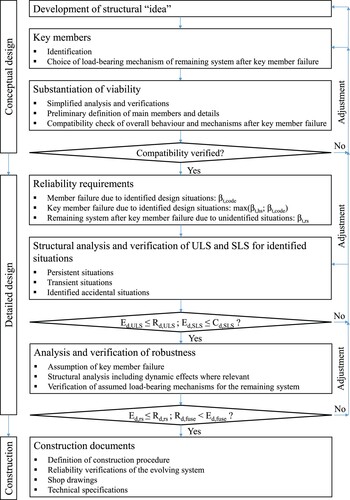
Building on the original structural idea, in the conceptual design phase the solution is formulated further to a series of consecutive sketches, while viability is substantiated through simplified structural analysis (). In addition to overall design, along with the main characteristics of the elements, the most important details should be defined at this early stage. The elements on which system stability depends, denominated ‘key members’ in the Eurocode,Citation4 should also be identified in this stage, along with the type of resistance mechanism to be brought into play after possible failure by creating alternative load paths or establishing collapse mechanisms. Simplified analysis and verification should address the compatibility between system properties and the failure mechanisms assumed. Where apparent or likely incompatibilities are identified, adjustments must be made. Such variations may range from changing the mechanism chosen to govern behaviour after failure of a key member or the layout of several members to, in some cases, redesigning all or some part of the system, i.e. rethinking the original underlying structural idea. Subsequent design should only be undertaken after the conceptual solution has been fully developed and system properties have been found to be compatible with the mechanism envisaged to enable the structure to resist possible key member failure.
Fig. 1: Structural design flowchart
Detailed Design
Specifying the degree of reliability sought is imperative to detailed structural design. The reliability index, β, based on a selected reference period, (typically 1 year or 50) can be used as a standard metric to express structural reliability.Citation4 The reliability requirement can therefore be defined in terms of a target reliability, βt, which depends among others on the expected consequences of failure, the relative cost of safety measures to increase the level of reliability and the chosen reference period.Citation14,Citation15 Inasmuch as the former two may differ depending on the failure mode envisaged, a distinction should be drawn among reliability requirements for ():
member failure due to identified design situations, βt,code;
key member failure due to identified design situations, max(βt,hs; βt,code);
collapse of the remaining system still standing after key member failure due to an unidentified accidental situation, βt,rs.
The target reliability for calibrating the partial factors used in structural design under the rules of a given code, βt,code, is a specific quantity,Citation4 usually proposed by the engineering community and approved by national authorities. The target reliabilities, which may be associated with indicative consequence classes according to some codes, often pursue economic optimisation.Citation14,Citation15 When failure is assumed to entail possible human death or injury, human safety should also be embraced by an additional reliability requirement, βt,hs. The likelihood of human loss of life or injury must be addressed when considering a hypothetical key member failure. The target reliability index for such members should therefore be taken as the greater of βt,hs and βt,code. Under an operational criterion suggested in an earlier study,Citation16 reliability requirements for human safety, βt,hs, were inferred from current practice and represented for a reference period of one year, varying with the area affected by the collapse, Acol, and the respective consequence class as defined in the Eurocode.Citation4 Although developed for building structures, those target reliabilities can be applied to the design of other load-bearing systems, particularly bridges, provided the number of persons at risk per unit area is of the same order of magnitude. These requirements have been improved recently.Citation17 It was further acknowledged that, in light of the ongoing presence of variables that remain unchanged over time (self-weight, strength variables if deterioration can be prevented and so on), annual reliability index targets might be lowered to accommodate the partial correlation of failure events across the years of a structure’s planned service life.
In terms of the remaining structural system left standing after key member failure, both the relevant design situations and the performance requirements depend on the design goal, e.g. rescuing any endangered people.Citation11 Given that in robust design the possible failure of a key member is assumed to be due to an unidentified accidental situation, target reliability for the remaining system, βt,rs, may be lower than calculated for persistent and identified accidental situations, since conditional reliability is envisagedCitation4. The target reliability, βt,rs, can therefore by found by factoring in the likelihood of scenarios that might induce key member failure, a parameter for which exact values cannot be determined and discussion of which lies outside the scope of this paper. Approximate values can be drawn from empirical estimates of the likelihood of specific natural and man-made hazards, which are available in the literature.Citation18–20
Structural analysis for detailed design should be conducted to established engineering theory and practice, taking the properties of the load-bearing system specified in the conceptual design into consideration. The partial factor format as defined in modern codes such as the EurocodeCitation4 is generally used to verify that no ultimate (ULS) or serviceability (SLS) limit state is exceeded. For ultimate limit states the action effects, Ed,ULS, established in the structural analysis are compared to the respective design strengths, Rd,ULS, for all persistent, transient and identified accidental situations and all significant load combinations and arrangements (). With this format the reliability requirements set out in the respective code are implicitly verified by using characteristic values for the random variables to which βt,code-dependent partial factors are applied. When a key member reliability requirement in connection with human safety is determined to be higher than the code requirement, βt,hs > βt,code, the partial factors used to verify the structural safety of the member must be raised in keeping with the former.
In the event of non-compliance with any given structural safety or serviceability requirement, one or more design parameters must be adjusted. Only minor changes (increasing the cross-sectional dimensions or using higher strength materials in the non-conforming components) should be required at this stage. Although more extensive changes may be made, any need in that regard denotes conceptual short-sightedness.
Lastly, the anticipated resistance mechanism of the elements remaining after key member failure must be verified for sufficient reliability. That calls for structural analysis of the static system as modified after hypothetical removal of the respective member to establish the action effects of the situations accruing during or after an unidentified accidental event. No explicit accidental action should be envisaged, although dynamic effects attributable to sudden system change must be taken into account. Determination of the design values of the action effects and the limit states to be verified depend on the type of post-key member failure resistance mechanism defined, i.e. on the robustness strategy chosen. If any of the limit states is exceeded, any adjustments required in the structural members should preferably be minor, although in some cases the choice of the resistance mechanism at issue must be revisited.
Construction Design
Once all the features of the structure have been determined in keeping with the results of iterative analysis, verification and optimisation, the construction design can be drafted. In addition to shop drawings and technical and organisational documents, this phase includes the detailed definition of construction procedures. Here, the reliability of the evolving system should be verified via specific analysis in terms of the interaction between the load-bearing system under construction and the respective ancillary resources used to build it.Citation21 Although no general consensus has yet been reached on the levels of reliability that should be demanded of temporary structures and activities, safety standards should be consistent with the same basic criteria as established for the permanent structures. Since the most prevalent transient situations should be taken into account in the detailed design, the specific definition of construction procedures in the construction design should not entail any significant structural modifications.
Hauterive Viaduct
Background
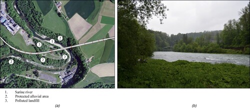
Due to the insufficient capacity of the existing infrastructure, a need has arisen for a new road to access south-eastern Fribourg, Switzerland, to accommodate ever heavier traffic. Further to the road layout, this access calls for the construction of an 840 m long, curved viaduct to span a bend in the Sarine River, a protected riverside area and a heavily polluted former landfill (). The importance of the viaduct and the demanding boundary conditions induced the authority responsible for its construction to organise a competition for its design.
Fig. 2: Location of the Hauterive viaduct: (a) plan view; (b) surrounds
Boundary Conditions
Geometry
Since the road layout was defined in the competition rules, entries were allowed only minor adjustments to the alignment. Carriageway geometry was also pre-determined, with a total width of 13.40 m for two lanes of traffic, one for micromobility (pedestrians and cyclists) separated by a barrier and the shoulder from the other, for motor vehicle traffic. Bridge landings and abutments could be freely positioned, provided the connection with the existing and future micromobility system was ensured. Construction was disallowed inside the protected area, as were foundations and bridge piers in others for a number of reasons. Although authorised in the polluted landfill, bridge piers built there would raise costs significantly relative to construction in less compromised ground, for they would have to be driven into a sealed well and would call for additional protective measures during construction.
Functionality
In addition to the aforementioned requisite to integrate micromobility into the carriageway, the functionality conditions included the need to take structural measures to prevent suicide. The bridge would also need to be fitted with a drainage system, with discharge into a treatment basin aligned with the longitudinal and transverse slopes of the carriageway. Noise amelioration was also afforded high priority, in part to protect a nearby Cistercian abbey.
Economy and Aesthetics
The competition rules explicitly identified project and maintenance feasibility, realistically defined, as one of the design objectives. The structural design was also expected to envisage architectural elegance in the aerial components of the Hauterive Viaduct, particularly in connection with their integration into the site and the natural surrounds.
The conclusion drawn from such design goals was that economic optimisation would be judged in terms of life-cycle, not merely construction, costs. The former comprise building costs and operating expenses, including user benefit, inspection and maintenance, refurbishment, depreciation and possible dismantling. Inasmuch as infrastructures are financed with public funds and spending the available resources cost-effectively is instrumental to good governance, substantial extra costs can be justified in very few bridges only, but certainly not in the Hauterive viaduct. An optimal balance had therefore to be struck between cost and structural elegance.
Competition Entry
Basic Ideas
The basic ideas underpinning the conceptual design of the competition entry for the Hauterive viaduct followed directly from the above conditions. With a view to designing a structure both reliable and robust, the principles set out in section ‘Conceptual design’ were followed to design a statically indeterminate system with high ductility. The general design aimed to make allowance for measures to protect against specific accidental actions such as vehicle impact. A second intention was to minimise dynamic effects by eschewing expansion joints, a measure that in addition to reducing fatigue and enhancing durability would lower noise levels. The load-bearing structure was designed as well to ensure ready accessibility for inspection and maintenance.
The principles governing bridge aestheticsCitation13 mentioned in section ‘Conceptual design’ were also applied to harmonise the structural demands with architectural elegance. Further to those principles, the structure was to blend into the surrounding landscape, the River Sarine and its banks in particular, but not to go unnoticed. The decision adopted was to design the bridge to the form-following-function principle, according to which structural form stems from functional requirements and site constraints.
The proposal submitted for the Hauterive Viaduct therefore consists in a steel and steel and concrete composite 10-span continuous double girder bridge. The considerable span length required to clear the broadest obstacle necessitated an extradosed structure for the girder in the main bay, even assuming construction of a pier in the landfill area (). That arrangement is effective in terms of both the final structural conditions and the building procedures, for the extradosed part is especially well suited to launched bridge construction in which no temporary bracing is required. The extra cost of building the foundations in the landfill area are more than offset by the reduction of the main span length.
Fig. 3: Structural idea for the Hauterive viaduct: (a) elevation (no construction possible in areas marked ‘N’); (b) cross-section of trough superstructure around the pylon, monolithically connected to the slanted pylon shafts and ties
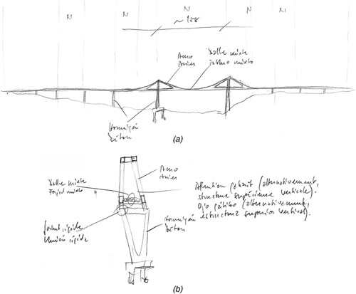
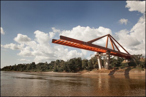
A solution successfully implemented by the designers in both railwayCitation22,Citation23 and roadCitation24 bridges, including construction based on incremental launching techniques (), was more fully developed for the load-bearing system proposed. The superstructure, defining a trough bridge, comprises two longitudinal steel box girders connected by transverse beams supporting the slab. Since the longitudinal girders protrude beyond the top of the slab, in the extradosed spans of the bridge they can be monolithically connected to the pylon shafts and ties (), both consisting of steel boxes of the same width as the girders and dimensions gradually increasing in the longitudinal direction of the bridge from the head of the pylon to the superstructure.
Fig. 4: Incremental launching during construction of the bridge over the River PachiteaCitation24 (© CESMA Ingenieros SL – Madrid)
The diamond-type pylons are A-shaped above and V-shaped below the superstructure. Both the ties and the longitudinal beam webs bear the same slant as the upper pylon shafts and consequently have a parallelogram-shaped cross-section. The pylon shafts are connected with two horizontal beams, one at the head forming a frame to enhance lateral stability, and the other at the transition between the A and the V to balance the corresponding deviation forces. With cross-sectional dimensions that grow both longitudinally and transversely from the superstructure downward, the shafts ultimately merge into a single member near the foundations.
The remaining bridge piers consist of reinforced concrete frames whose shafts are aligned with the main girders supported and connected by a horizontal beam at the top to ensure transversal stability. The pier shafts bear the same slant as the V-shaped shafts on the under part of the pylons. The transverse dimension of their cross-sections grows in the downward direction while the longitudinal dimension is constant. Further to the geotechnical survey results, the bridge piers and abutments call for pile foundations, whereas shallow foundations suffice for the pylons.
Structural System
Minor adjustments introduced in the longitudinal profile of the structure and abutment locations yielded a 762.5 m long bridge comprising 10 spans ranging in length from a minimum of 37.5 m to a maximum of 175 m (a). Span lengths gradually shorten to accommodate the decline in superstructure elevation in the western (towards C-1) and eastern (C-2) directions (numbering in the direction of increasing chainage): 37.5 m - 55 m - 67.5 m - 115 m - 175 m - 115 m - 60 m - 50 m - 47.5 m - 40 m. The substantial difference in elevation translates into pier heights varying from 3.8 m (P-1) to 51.5 m (P-5). The pylon shafts rise approximately 20 m above the longitudinal girders to form the extradosed system supporting the main and two adjacent spans. The loads are transferred by stiff ties running from the deck to each shaft head. The tie-girder connections are spaced at approximately 57 m from the pylon axis. These arrangements afford elastic supports across each third of the main 175 m span and midway across the two 115 m adjacent spans.
Fig. 5: Competition entry (Dr Lüchinger + Meyer Bauingenieure AG – Zürich; CESMA Ingenieros SL – Madrid; Ilg Santer Architekten – Zürich): (a) longitudinal section; (b) bridge pier P-8; (c) superstructure cross-section (Units: m)
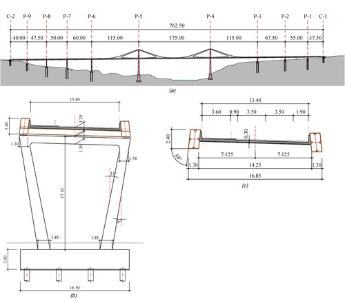
Like the pylon shafts, the tallest of the remaining piers, P-6 and P-7, are monolithically connected to the longitudinal beams. In contrast, the shorter piers positioned closer to the abutments are fitted with bearings to accommodate translational movement in the longitudinal direction (b). Both abutments also feature longitudinally movable bearings and an expansion joint. Under such support arrangements, the viaduct constitutes a flexible system with no physically defined fixed point in the longitudinal direction.Citation13 Longitudinal stability is ensured by the action resulting from the portal-framed structure of piers and pylons and their monolithic connection to the superstructure. Pier buckling lengths are consequently less than or equal to their height. The transverse forces attributable to wind, earthquake or other actions, in turn, are transferred from the superstructure to the foundations across the portal frame-structured piers (section ‘Basic ideas’).
Members
In keeping with the characteristics of the cross-section defined for the superstructure, total clear width, kerbs and parapets are also set between the two box girders (c). With a cross-sectional height of 2.4 m and a maximum approach span length of 67.5 m, the slenderness ratio is 28, a characteristic value for continuous steel or steel-concrete composite box girder bridges.
Closed cross-section longitudinal stiffeners are positioned on box girder flanges and webs to guard against instability. The frame-type diaphragms that afford access to girder interiors for inspection purposes are spaced at 5 m intervals aligned with the transverse beams that support and are connected to the slab, a member consisting in precast and cast-in-place concrete slabs. The 0.08 m thick precast slabs, which serve as formwork for the freshly poured concrete, are built into the monolithic 0.3 m high deck system by means of welded lattice-type reinforcement. The parapets, likewise integrated into the slab, are deemed in superstructure design as non-load bearing and therefore replaceable as required for bridge maintenance.
The original intention to build the ‘V’ (lower) part of the pylons from concrete was ruled out at an early stage in favour of the steel shafts also envisaged for the ‘A’ (upper part) to simplify construction. In the longitudinal direction of the bridge, the cross-section of these lower shafts varies gradually from 2.0 m at the top to 3.63 m at the base. In the transverse direction, the section features the same constant 1.3 m width as the main girders (section ‘Basic ideas’) above the deck while varying below it ().
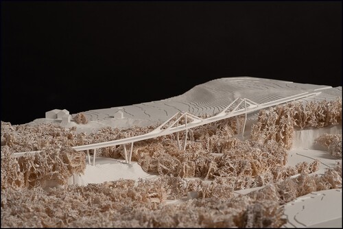
Fig. 6: Model of the solution proposed and surrounds (model building: Zaborowsky Modellbau GmbH)
The tie section also consists in steel boxes likewise of the same constant width as the main girders. Section height varies between the head of the pylon and the point where the ties merge with the main girders.
The prestressed monolithic connection between the main girders and piers P-6 and P-7 is essential to bridge longitudinal stability. The respective tendons are positioned in the concrete section of the piers and course through openings in the bottom flanges of the girders. They are anchored inside the girder cross-section.Citation24
Robustness
The combination of strategies described earlier is applied to meet robustness requirements. In the proposal for the Hauterive Viaduct the ties and pylons must unquestionably be deemed key members as defined in section ‘Structural design’. In the event of a tie failure due to an unidentified accidental situation, robustness can be ensured with sufficient redundancy and appropriate design of the remaining structure. An alternative load path is envisaged as combined catenary and three-dimensional bridge deck behaviour, in order to avoid the possibility of an accident similar to that of the viaduct over the Polcevera river in Genoa, in which, according to the study,Citation25 the loss of a stay could have triggered the progressive collapse. The structural model of the bridge over the Pachitea RiverCitation24 is used to illustrate the pattern devised (). Non-collapse of the remaining system should be verified by comparing the design value for action effects in a certain cross-section, element or sub-system, Ed,rs, to the design value of the respective strengths, Rd,rs. Compliance with condition (EquationEq. 2(2)
(2) ) must be ascertained for all pertinent situations and all limit states in a given period of time, to be defined by agreement between the parties, during which collapse must not be propagated:
(2)
(2)
Fig. 7: Verification of post-tie failure system behaviour in a redundantly designed, extradosed bridge
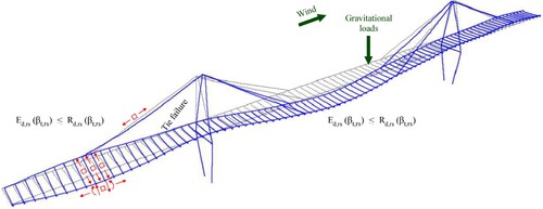
The design value of the action effects, Ed,rs, can be determined on the grounds of the combination of actions for accidental design situations set out in structural design codes such as the Eurocode.Citation4 Permanent actions must always be included, whereas no consideration is given to any explicit accidental action (Ad = 0) subsequent to the notional removal of the tie. Variable actions and influences to be considered and the choice of the most suitable combination factor, ψ, depend on the situation analysed.Citation4 Account must be taken of the dynamic effects induced by sudden system change. The partial factors applied to actions and their effects may be lowered compared to code values in keeping with the reliability requirements established for the remaining system, βt,rs (section ‘Process’). Analogously, the design strength values, Rd,rs, may be determined applying lower partial factors for material properties, geometric deviations and resistance model uncertainties, likewise depending on βt,rs.
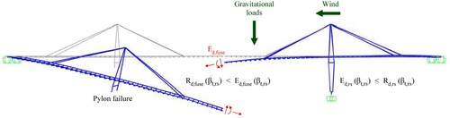
Since alternative load paths can hardly be provided in the event of pylon failure, the proposal for robust design entails envisaging a weak mid-span cross-section, or fuse, in the main span. Following the planned construction procedure by incremental launching from both river banks (section ‘Basic ideas’), the mid-span segment only needs to withstand the effects of the actions applied after the two cantilevers have been connected. Its load-bearing capacity can therefore be considerably lower than that of the adjacent segments in a way that, if strictly designed, pylon failure due to an unidentified accidental situation would transpire in keeping with a mechanism similar to the one depicted in , again using the structural model for the River Pachitea bridge.Citation24 For those intents and purposes, the design fuse strength, Rd,fuse, must be compared to the respective action effects, Ed,fuse. All the pertinent situations arising during or immediately after pylon failure must meet condition (EquationEq. 3(3)
(3) ) for the predominant limit state defined in the built-in failure mechanism:
(3)
(3)
Fig. 8: Verification of post-pylon failure built-in fuse and system behaviour in a redundantly designed, extradosed bridge
Verification should be conducted in the understanding that high strength and low action effect values are detrimental to satisfactory fuse behaviour. Consequently, when determining the design action effects, Ed,fuse, lower characteristic values should be used for any permanent actions present,Citation4 no explicit accidental action must be factored into the analysis and, depending on the situation, quasi-permanent values can be applied for variable actions.Citation4 Where favourable, the effects of variable actions should likewise be excluded. Conservative values should also be adopted for the dynamic effects of abrupt pylon failure. Conversely, the upper limit of the characteristic material strength values should be used to determine design fuse strength, Rd,fuse. Condition (EquationEq. 3(3)
(3) ) is subsequently verified by multiplying the strength variables by the respective partial factors, whilst the characteristic action values are divided by the partial factors for actions and their effects. All partial factors may be lowered in keeping with post-key member failure reliability requirements, βt,rs (section ‘Detailed design’).
In the Hauterive Viaduct (a), pylon (P-5, for instance) failure would be followed by fuse failure in the centre of the main span and the formation of a plastic hinge in the longitudinal girders over adjacent pier P-6. If correctly designed, the remaining structure and more specifically the extradosed system between the centre of the main span and pier P-3 will satisfy condition (EquationEq. 2(2)
(2) ), preventing collapse from propagating. That notwithstanding, this built-in failure mechanism affects the bridge superstructure across more than 200 m (50% of the main and adjacent spans). Given the 13.40 m total width of the carriageway and the absence of underlying infrastructures, residential neighbourhoods or industrial facilities, the area that would be affected by collapse would come to approximately Acol = 2700 m2. With such a large area affected by possible pylon failure for whatsoever design situation, stricter reliability requirements may need to be demanded of pylons than of other bridge members in persistent and identified accidental situations (section ‘Collapse stop and risk-based design for key members and the remaining structure’). If the bridge is classified under standard EurocodeCitation4 consequence class CC2 (ordinary road, not a motorway bridge; location outside populated areas; presence of alternative access thoroughfares), the requirement to reliably ensure human safety, βt,hs,1y,Citation17 that must be used in pylon design in persistent situations is higher than specified in the Eurocode, βt,EN1990,1y.Citation4 The reference period used for comparison is Tref = 1 year:
(4)
(4)
Although none of these values factors the partial correlation of failure events in subsequent years into the calculation (section ‘Detailed design’), this result calls for partial factors for verifying pylon structural safety in persistent situations higher than the values recommended in the Eurocode.Citation4 Analogously, the design action effects and respective strengths may have to be adjusted to verify structural safety in identified accidental situations.
Conclusions
Since the successful translation of many constraints into an aesthetically appealing as well as reliable, functional and cost-effective structure is primarily a question of sound conceptual design, the importance of this step in the design process as a whole cannot be overstated. Nonetheless, the growing complexity of analysis and verification methods, materials technology and construction procedures is driving ever greater specialisation against a backdrop of increasingly extensive and opaque standardisation and control systems. Such specialisation comes at the expense of conceptual design training in engineering schools and consequently of structural engineers’ creativity and other skills necessary to create compelling designs for structures.
Rules for robust design can be cited as representative of increasing code opacity. Although the importance in practice of designing and building robust structures cannot be refuted, code rules in that regard are often extremely vague, sometimes contradictory and generally lacking in any clear design philosophy. They may therefore be confusing for designers and ultimately counterproductive. Conversely, that lack of clarity for robust structural design, an outcome of the complexity of the problem itself, may spur careful or even innovative solutions if suitable mechanisms are built into the load-bearing system early, in other words in the conceptual design phase.
Building on that premise, this contribution suggests a practical approach to robust bridge design. The general idea is that conceptual design should embrace continuous, ductile structural systems given their inherent advantages for identified design situations, such as moment redistribution capacity and energy dissipation. Preventing the propagation of key member local failure-induced collapse in unidentified accidental situations would call for building either alternative load paths or predefined collapse mechanisms into such systems. Such measures should be combined with risk-based criteria in key member as well as remaining structure design. Deployment of the procedure proposed afford reasonable assurance that the actual load-bearing mechanism called into play after local failure in the wake of unidentified accidental situations would be as assumed. It would also ensure that possible failure of members on which structural system strength and stability depend entails no higher risk to persons than implicitly consented in present practice. The reliability requirements for the remaining system still standing after unidentified accidental situation-prompted local failure depends on the likelihood of such scenarios. Estimating those values is logically far from straightforward and the suggestions found in the literature published to date are based on gross simplifications. Future research should therefore address refinement of the verification criteria for remaining structures after local failure.
The ideas underlying the conceptual design for road bridges put forward here are illustrated with an example in which economically feasible satisfaction of all structural safety requirements is shown to be compatible with architectural elegance. That outcome is subject, however, to observing the basic criteria governing structural form, integration into the environment, structural transparency, slenderness and harmony.
References
- Billington D. The art of structural design: a Swiss legacy. Princeton (NJ): Princeton University Art Museum, 2003. ISBN 0-300-09786-7 (cloth), 943812-38-4 (paper).
- Leonhardt F. Brücken – bridges. London: The Architectural Press Ltd, 1982. ISBN 0 85139 764 6.
- Muttoni A. L’art des structures. Lausanne: Presses polytechniques et universitaires romandes, 2004. ISBN 2-88074-554-3
- prEN 1990:2020. Eurocode – basis of structural and geotechnical design, Enquiry Draft, European Committee for Standardization, CEN, Brussels, 2020.
- CEN/TC 250/WG6.T2. Robustness rules in material related Eurocode Parts, Report of Project Team WG6.T2, European Committee for Standardization, CEN, Brussels, 2020.
- Starossek U. Progressive collapse of structures. London: ICE Publishing, 2018. ISBN 978-0-7277-6168-2.
- Melchers RE. Structural reliability – analysis and prediction. Chichester: Ellis Horwood Series in Civil Engineering, Ellis Horwood Ltd., 1987. ISBN 0-85312-930-4.
- Tanner P, Bellod J, Sanz D. Paper and pencil in the age of BIM. Struct Eng Int. 2018; 28(4): 396–407. ISSN 1016-8664.
- JCSS and IABSE. Robustness of structures – workshop, BRE, Watford, Joint Committee on Structural Safety and International Association for Bridge and Structural Engineering, Zürich, 2005.
- EN 1991-1-7. Eurocode 1 – actions on structures – Part 1-7: general actions – accidental actions, European Committee for Standardization, CEN, Brussels, 2006.
- Tanner P, Hingorani R. Robustness: a practitioner’s perspective, IABSE Symposium Guimaraes, Towards a Resilient Built Environment – Risk and Asset Management, Report, Zürich, 2019, pp. 1444-1451. ISBN 978-3-85748-163-5.
- Baus U, Schlaich M. Footbridges. Boston, Berlin: Birkhäuser Basel, 2008. ISBN 978-3-7643-8139-4
- Menn C. Prestressed concrete bridges. Basel: Birkhäuser, 1990. ISBN 3-7643-2414-7, 535 Pages.
- ISO 2394. General principles on reliability for structures. Geneva: International Organization for Standardization, ISO, 2015.
- JCSS. Probabilistic model code, Joint Committee for Structural Safety, 2001, jcss.byg.dtu.dk.
- Tanner P, Hingorani R. Acceptable risks to persons associated with building structures. Struct Concr. 2015; 16(3): 314–322. doi:10.1002/suco.201500012.
- Hingorani R, Tanner P. Risk-informed requirements for design and assessment of structures under temporary use. Risk Anal. 2020; 40(1): 68–82. doi:10.1111/risa.13322.
- Ellingwood B. Mitigating risk from abnormal loads and progressive collapse. Journal of Performance of Constructed Facilities. 2006; 20(4): 315–323.
- Stewart M. Life-safety risks and optimisation of protective measures against terrorist threats to infrastructure. Struct Infrastruct Eng. 2011; 7(6): 431–440.
- Vrouwenvelder T, Leira B, Sykora M. Modelling of hazards. Struct Eng Int. 2012; 22(1): 73–78. ISSN 1016-8664.
- Tanner P, Hingorani R, Bellod J, Sanz D. Thoughts on construction risk mitigation and acceptance. Struct Eng Int. 2018; 28(1): 60–70. ISSN 1016-8664.
- Tanner P, Bellod J. Salto del carnero railway bridge, Saragossa, Spain. Struct Eng Int. 2006; 16(3): 200–203. ISSN 1016-8664.
- Janberg N, Krontal L. Eisenbahnviadukt Torrejón de Velasco, Madrid, Spanien, In: Eisenbahnbrücken, Wilhelm Ernst & Sohn Verlag für Architektur & technische Wissenschaften GmbH & Co. KG, Berlin, 2014, Seiten 64-65, ISBN 978-3-433-03097-4.
- Bellod J, Sanz D, Tanner P, Aita D. Puente sobre el río Pachitea en Puerto Inca, Perú, Hormigón y Acero, Vol. 68, Especial Congreso, 2017, Página 37, ISSN 0439-5689.
- Calvi G, Moratti M, O’Reilly G, Scattarreggia N, Monteiro R, Malomo D, Calvi P, Pinho R. Once upon a time in Italy: the tale of the Morandi bridge. Struct Eng Int. 2019; 29(2): 198–217. ISSN 1016-8664