
Abstract
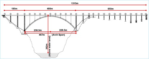
The new bridge across the deep gorge of the Chenab River in the remote mountains of Jammu and Kashmir is a key component of the Udhampur–Srinagar–Baramulla Rail Link (USBRL) project. The bridge is 1315 m long in total. Its main arch with a span of 467 m and land pier heights of up to 131 m place the bridge at an imposing 362 m above the river water level, making it the World’s tallest railway bridge. Although the site location has been carefully chosen, yet the terrain itself is the most difficult from an engineering design and construction point of view. The slopes of the bank are very steep and consist of highly jointed dolomite strata. Extensive slope stabilization analysis was carried out and optimum measures were adopted and implemented successfully for slope stabilization works. The steel superstructure was erected using the incremental launching method. The report briefly highlights the various challenges faced in the project implementation and presents the most salient design aspects.
Introduction
The Udhampur–Srinagar–Baramulla Rail Link (USBRL) Project is a National Project of the Government of India for providing rail connectivity for the Kashmir Valley to the mainland of India. The project is fraught with complex engineering structural challenges in this seismically active Himalayan terrain.Citation1 Chenab Bridge itself crosses a deep gorge of the Chenab River 125 km north of Jammu City.
At the moment of writing, the bridge is complete apart from finishing works and final load testing.
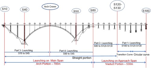
The total length of the bridge is divided into two parts for design and construction purposes (), i.e. the arch portion of length 785 m and the viaduct portion of length 530 m. The deck is continuous in each portion and special rail and bridge expansion joints are provided at the S10, S70 and S180 locations. The arch portion is on straight alignment. The viaduct portion is partly on straight and curved alignments (circular and transition curves). The arch and piers are composed of hollow steel boxes joined in the field by Geomet® coated High Strength Friction Grip (HSFG) bolts. They were erected with the help of the World’s largest tandem cable crane, which has a cross bar having a capacity of 34 t on a single hook. The piers of the viaduct are composed of hollow rectangular concrete sections and constructed by slip forming. The decks on both the viaduct and arch portions were launched separately and incrementally from both sides.
Fig. 1: General arrangement of Chenab Bridge
Logistics
The Chenab Bridge site is located 125 km north of Jammu City, which has connectivity by all means of transport, except that 40 ft long trailers can only travel from Jammu to Reasi Town, which is about 75 km away from Jammu. From Reasi to the Chenab Bridge site (50 km), the road used to be predominantly single lane with steep gradients and sharp curves, making the access to the site very difficult and restricting transportation capacities to 20 ft trailers. Hence, a transshipment facility was created at Reasi and the equipment/materials were shifted from 40 ft trailers to 20 ft trailers and transported onwards to the site.
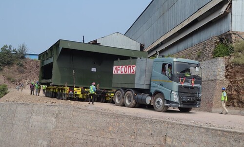
At the site, deck segments of maximum size 17.5 m × 8.33 m × 4.5 m (100 t) posed the greatest transportation challenge, which was mastered by special multiaxial and hydraulically steered trailers ().
Fig. 2: Transportation of segments. Photo by Chenab Bridge Project Undertaking (U/o AFCONS Infrastructure Limited)
Slope Stabilization
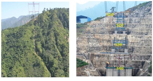
Seven out of eighteen foundations of the bridge, i.e. S10 to S70, including the crucial arch foundations (S40 and S50) have been constructed on the steep slopes of the river gorge. The strata are predominantly highly jointed dolomite with open joints and cavities.Citation2 The bridge is in the highest seismically active zone, i.e. Zone 5 of the Seismic Zone Map of India, with a peak ground horizontal acceleration of 0.36 g. Elaborate and sophisticated geotechnical, geological and geophysical tests were carried out. The orientation of the joints and the joint parameters were considered in the analyses, which pointed to the possibility of wedge failures. Slope stabilization measures using steel fibre reinforced shotcrete, passive rock bolts and double corrosion protected prestressed anchors were used.Citation3 The design of the slope stabilization measures was carried out based on the “Top-Down” method of excavation for slopes following the contours. Design parameters were monitored and continuously validated as the excavation progressed. Typical finished slopes of the Bakkal side banks are shown in . Similar slope cutting was executed on the Kauri side banks.
Fig. 3: Before and after excavation for slope stabilization. Photos by Chenab Bridge Project Undertaking (U/o AFCONS Infrastructure Limited)
Construction of Arch and Steel Piers by Cable Crane
All steelwork on the slopes of the river gorge, including the iconic arch itself, were erected by the World’s largest cross bar cable crane supported by 127 m tall pylons spaced at a distance of 915 m. The cross bar cable crane is composed of two units having a lifting capacity of 20 t each. This lifting capacity can be increased to 34 t on a single hook when operated in tandem.
The overall complex geometry of the bridge required detailed procedures and fine adjustment to lift all assemblies at the correct inclination in two planes considering their exact centres of gravity.
Lifting of Tapered Pier Segment
The steel piers of the bridge are tall structures on massive foundations. Each spliced element of the pier is composed of column sections of 10 to 12 m in height. The pier bracings are connected to a common “Star” gusset assembly and were lifted in separately. Pier column segments weigh around 15–20 t and were lifted and installed at an angle of 86° for Piers S20, S30 and S60, and 83° for Piers S40 and S50. The lifting scheme was developed as a three-point lifting system, i.e. two points at the top of each pier element and one point at the bottom. The third point or the bottom point consists of a ratchet hoist arrangement, which facilitates any fine adjustment required for inserting bolts at the splice location.
Arch Erection Method
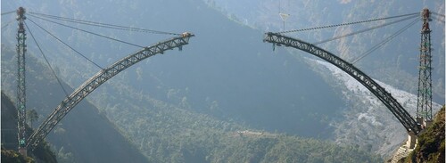
The arch was erected simultaneously from the Bakkal and Kauri sides by cantilever construction technique. Strand system stay cables supported the cantilevers temporarily at the future trestle locations, resulting in free cantilevers of approximately 50 m before the next set of cables was installed.
There were two types of temporary cable, i.e. the forestay cables spanning between the arch front end and a temporary tower, and backstay cables connected between the temporary tower and stiff supports at the S10 and S20 foundations on the Bakkal side and the S70 and S80 foundations on the Kauri side.
When the first set of forestay cables was installed to support the cantilever arms near the S41 and S49 locations, backstay cables were simultaneously tied to rigid anchor points at S20 and S70. All cables were stressed from the temporary tower. The installation and stressing of the first cables in particular was planned and executed in a very refined sequence since the freestanding 131 m tall support piers can accommodate only limited differential horizontal forces. Weather forecast and wind speed limits had to be observed to enable this operation.
Owing to the addition of more and more cables (), the pier was stiffened in the longitudinal direction and its movements reduced. Despite the lowering sensitivity to force differentials, a quasi-simultaneous stressing sequence remained essential and was controlled by permanent monitoring of the pier top.
Fig. 4: Arch supported by temporary stays. Photo by Chenab Bridge Project Undertaking (U/o AFCONS Infrastructure Limited)
The cantilever tip of the arch and the temporary pier position were surveyed at every construction activity and change in loading. The site was equipped with calculation sheets to check at any time whether the deflections were within tolerance limits, including temperature correction. At predetermined intervals or trigger levels, the data were delivered to the designer for review and supplemented by a set of current stay cable forces when required.
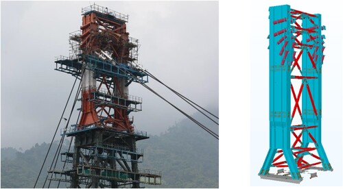
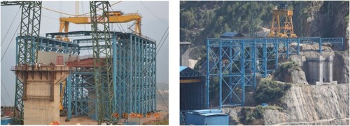
Temporary Tower for Suspension of Temporary Stays
For holding the forestay and backstay cables, temporary towers () were installed on top of Piers S40 and S50. The support of the arch by the stays became more effective with increasing inclination of the forestay cables, hence the temporary towers had to be as high as possible.
Fig. 5: Temporary tower above pier and 3D model of temporary tower. Photo by Chenab Bridge Project Undertaking (U/o AFCONS Infrastructure Limited)
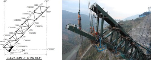
Installing the Arch Spine
The overall arch structure is composed of two plane arches (i.e. upstream and downstream arches) that lean towards each other at an angle of 4.23° to the vertical. Wind bracings interconnected the two arches and took horizontal loads during construction and also in the permanent service condition.
The lifting scheme was devised in such a way that the elements were inclined at angles varying from 51° (base of arch) to 0° (arch crown) in elevation and at a constant angle of 4.23° reflected in the cross section (). The top chord segments were lifted in assembly with the diagonals.
Fig. 6: Three-point lift of arch bottom chord. Photo by Chenab Bridge Project Undertaking (U/o AFCONS Infrastructure Limited)
Wind Bracing Erection
The wind bracings consist of pipe sections and have a gusset connection inclined in three directions with connections to the edge of the arch as well as at its centre. At the abutment, the two arch spines have a clear distance of around 25.5 m, which is reduced to 6.0 m at the arch crown. This results in wind bracing elements with lengths up to 40.0 m.
Lifting with multiple slings and temporary spreader beams spanning between the arch spines enabled successful erection within tolerance limits ().
Fig. 7: Snapshot of wind bracings and erected first set of wind bracings. Photo by Chenab Bridge Project Undertaking (U/o AFCONS Infrastructure Limited)
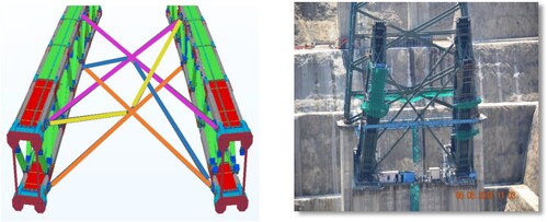
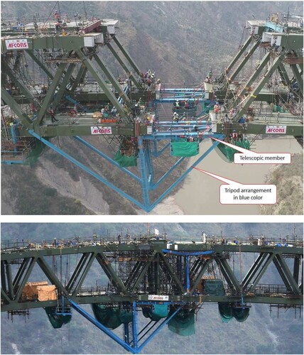
Arch Closure
The arch was closed by jacking the two cantilever ends apart using a tripod jacking system (). In order to achieve the correct final forces and bending moments in the arch, the procedure was staged. At first, the bottom chords were jacked apart and connected by a hinged chord element. In the second stage, the top chords were jacked apart, which activated the correct forces for this stage in both chords.
Fig. 8: Arch closure by tripod and telescopic struts. Photos by Chenab Bridge Project Undertaking (U/o AFCONS Infrastructure Limited)
Arch Box Concreting
Subsequent to arch closure, the temporary stays were uninstalled and the arch chords filled with M40 concrete. The casting process was done in several steps. In each concrete step, an arch length of approximately 10 m was cast. The casting was done quasi-simultaneously for all arch legs. All concreting of each concrete step had to be finished in every arch leg and the concrete hardened to 25 MPa before the next concrete step started.
Incremental Launching of Spans
The incremental launching scheme was divided as follows ().
Incremental launching on viaduct spans. The segment incremental launching was further divided as follows.
Part 1 – curved incremental launching from S180 to mid S120 and S130.
Part 2 – straight incremental launching from S80 to mid S120 and S130.
Incremental launching over arch. The segment incremental launching was further divided as follows.
Part 3 – straight incremental launching over the arch portion from Abutments S10 to S45.
Part 4 – straight incremental launching over the arch portion from Piers S80 to S45.
Fig. 9: Incremental launching scheme
Incremental Launching on Viaduct Spans
The viaduct portion of the bridge is composed of a circular curved axis (radius 638.686 m), a transition curve axis of 110 m length and a 1065 m long straight axis. Since the project is in hilly terrain and the deck was being designed as a continuous deck over supports, it was decided to adopt incremental launching for the construction of the deck.Citation4 The incremental launching was carried out in two stages from both ends. In the first stage, the deck was launched from Abutment S180 on a combined circular and transition curve, and in the second stage, the deck was launched from Pier S70 on the straight portion.
Straight Viaduct Spans
Launching platforms were constructed at S180, S80–S70 and S10 to launch the segments by the incremental method (). Platform S80 served the purpose of launching segments of viaduct spans from S80 to the mid length of S120/S130 (Part 2). The main arch span segments from S80 to the arch crown were also launched from Platform S80 (Part 4).
Fig. 10: Launching Platform at S80 and at S10 Location. Photos by Chenab Bridge Project Undertaking (U/o AFCONS Infrastructure Limited)
A launching nose 36 m long was connected before the start of incremental launching at the front end of the segment using HSFG bolts to reduce the cantilever moments on the segments being launched.
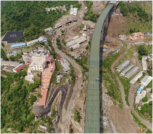
Curved Viaduct Spans
In curved spans, incremental launching of the deck was carried out on a combined circular and transition curve by fabricating the deck following the alignment of the bridge and launching the deck along a predefined launching curve using central guidance and wide temporary bearings. This innovative method was developed by the contractor and had never been used before. The deck was fabricated and joined as per designed horizontal alignment. However, the launching was carried out on a theoretical launching curve of radius 720.894 m, which had been determined by trial and error. The central guide beam was connected to the lateral bracing structure under the segment, along the theoretical launching curve.
When the deck was launched, the guidance beam actually followed the launching curve, as designed. At supports, the lateral position of the deck was changing all the time and movements were accommodated by wide sliding pads. A photograph of the completely launched deck may be seen in .
Fig. 11: Incrementally launched deck on combined circular and transition curve. Photo by Chenab Bridge Project Undertaking (U/o AFCONS Infrastructure Limited)
Straight Arch Spans
From Abutment S10 to the mid length of the arch span (Part 3), eight spans were launched totalling 51 segments. The main span segments were pulled from a specially designed pulling frame mounted on Abutment S10.
The segments were launched from the top level of Abutment S10, which is approximately 39 m above the fabrication shop level. A temporary platform with a 140 t gantry was designed at S10 for moving and placing 120 t segments. The welding and launching of segments was carried out on the launching platform. The location of the launching platform had been decided in such a way that segments could be transported from the workshop to the launching pad without using a trailer.
After all the piers had been erected, the pier heads were connected to each other by stressing horizontal temporary ties between them. Tendons were anchored to end supports and the arch crown. In this way, friction forces created by launching were transferred to stiff supports and bending of piers was minimized.
After finalizing the stressing of tie tendons, the allowable deformation at the pier heads was limited to 1/1000 of their height and readjustment of the force was done in the temporary tendons as required.
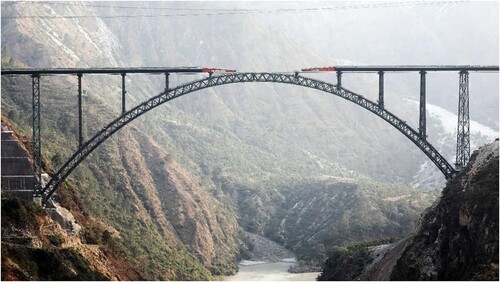
Launching of the superstructure was done simultaneously from both ends, i.e. S10 from the Bakkal side and S70 from the Kauri side. One side was permitted to be ahead of the other by a maximum of two spans to limit bending of the arch. Finally, after joining the superstructure from both sides by the so-called “Golden Joint”, the bridge was structurally complete, paving the way to constructing track laying and associated activities ().
Fig. 12: Deck launching over arch span. Photo by Chenab Bridge Project Undertaking (U/o AFCONS Infrastructure Limited)
Conclusions
The Chenab arch bridge is one of a kind and an example of the highest levels of accuracy and precision at every stage of design and construction. This impressive result was achieved by considering the erection methods from the earliest design stages on, and through close collaboration between the designers and the contractors’ engineers, who together developed a multitude of feasible and innovative solutions to each construction challenge.
In particular for the overall arch erection sequence, the arch closure and the superstructure launch, the team considered several construction options. Final solutions were chosen jointly, considering the ease of construction and any associated risks, but also the efficiency of realizing the respective operation at the inclement bridge location and at the given scale.
A detailed erection manual summarized the decisions and the results of the erection stage analysis. Detailed data sheets gave the site team a full understanding of the geometry target values versus monitoring and survey data. Hence the site was in immediate control of the bridge geometry and reverted to the designers only when pre-determined trigger values or construction stages were reached. State-of-the-art fabrication methods and trial assemblies vastly reduced any fitting issues during erection.
Precise planning, optimum designs, teamwork and safe construction methods led to a structure within all tolerances and, above all, to 11.47 million safe working hours on this project to date.
Pictures by Chenab Bridge Project Undertaking (U/o AFCONS Infrastructure Limited).
Disclosure Statement
No potential conflict of interest was reported by the authors.
References
- Pulkkinen, Karius and Kiviluoma. Design of the Chenab bridge in India. IABSE symposium, Kolkata, India; 2013.
- Hoek E. Strength of jointed rock masses. Twenty-third Rankine Lecture Presented to the British Geological Society in London on February 23, 1983 and Published in Géotechnique. 1983;23(3):187–223.
- Mantrala S, Kumar H, Verma AK, Sitharam TG. 2019. Stabilization of highly jointed rock mass slopes of the world’s highest railway bridge across the deep gorges of Chenab river. International Conference on Landslides and Slope Stability, Bali, Indonesia.
- Rosignoli M. Bridge Launching. Parma, Italy: Thomas Telford; 2002.