
 ?Mathematical formulae have been encoded as MathML and are displayed in this HTML version using MathJax in order to improve their display. Uncheck the box to turn MathJax off. This feature requires Javascript. Click on a formula to zoom.
Abstract
In the design of in-plane stressed thin plates, the load condition where the distributed edge shear is locally applied along the plate boundaries is often encountered and has thus far not been well investigated. This load configuration can induce buckling instability. The problem of shear buckling instability in such applications has so far received very little attention from researchers owing to the additional analytical difficulties involved in obtaining rigorous solutions to the buckling of plates when subjected to partial loadings, and the present research aims to address the problem and present a rigorous solution. It focuses on investigating the problem of linear and nonlinear buckling of simply supported thin plates subjected to local in-plane shearing using the finite element method. The critical shear buckling stress is determined for different load cases applied to a judiciously designed plate specimen. Compressive, shear and von Mises stress analyses are conducted. The results achieved are summarized as tables, graphs and iso-stress contours. It is shown that the stability effect of the load ratio on the specimen is reached when the load extent covers 55% of the plate sides. The plate buckling in the length direction is justified by significant compressive stresses recorded in this direction. It has been found that, at buckling, a compressive diagonal field action occurs. Finally, the von Mises analysis shows that plasticization occurs at the plate length loading stop points.
Introduction
Structural elements, especially thin plates are commonly used in many engineering industries such as aircraft and aerospace, bridges and offshore platforms, and the marine and ship-building industry. Such elements undergo several types of forces, and in particular partial in-plane shear loading. This latter can induce buckling and neglecting the impact of such a phenomenon on the plate behavior can lead to total collapse. Patch loading is encountered in many practical situations in engineering. For example, in the launching of bridges, a patch load is applied on the steel girder. The impacts of the patch load must be well understood in order to design the web plate properly. Another example is that of the in-plane patch loading produced on crane web panels by the distribution of a wheel load through an overlying rail and flange, leading to elastic buckling. Roof panels are often subjected to variable patch loading, and it is necessary to understand how such loading affects the design.
The problem of uniform sheared rectangular plate buckling was initially solved through the plate governing differential equation, the development of which was due to the contributions of many authors.Citation1–3 The analytical solution stemming from the energy method was first studied by Ref. [Citation4]. Using the same procedure, Refs. [Citation5], [Citation6] and [Citation7] proposed accurate solutions for specific boundary conditions. Reference [Citation8] gathered together these results reached in a section of his manuscript. Reference [Citation9] used the multi term extended Kantorovich method to derive the in-plane shear buckling load for thin elastic compressed plates. In their work, the authors transform the partial differential equations into a system of ordinary differential equations leading to a quite interesting converging process.
The finite difference method was applied by Ref. [Citation10] to analyze the influences of linear variations of the thickness, plate aspect ratios and boundary conditions on the buckling behavior of a rectangular thin plate subjected to uniform shear loading. The authors deduced that the increase in the plate tapering ratio decreases the buckling coefficient value.
Recent work conducted by Ref. [Citation11] has provided solutions to determine the elastic shear buckling load using the spline finite strip method for a uniformly sheared perforated square plate and for a whole thin-walled lipped channel section with a centrally located hole. In his article, the author proposed approximate equations for shear buckling coefficients that can be used for design purposes. Using the same external loading, Ref. [Citation12] showed that the differential quadrature method can yield an accurate buckling load for a simply supported rectangular plate.
Reference [Citation13] studied the shear buckling and stress distribution in trapezoidal web corrugated steel beams both experimentally and numerically.
Based on the finite element analysis results obtained in their investigation, Ref. [Citation14] proposed a formula to improve the calculation of the local shear buckling strength of trapezoidal corrugated steel webs. In seeking the optimum location and number of plate stiffeners for plates subjected to uniform shear loading, Refs. [Citation15] and [Citation16] used eigenvalue buckling analysis performed by means of the finite element method. The results they reached were proposed for practical steel design. Later on, Ref. [Citation17] carried on their work by numerically studying the influence of surrounding member rigidities on the elastic shear buckling and post-buckling behavior of thin steel panels uniformly sheared.
The ultimate strength of perforated steel plates under combined bi-axial compression and uniform edge shear loading was investigated by Ref. [Citation18] using finite element analysis. Also, particular forms of uniformly sheared thin plates were successfully analyzed by many researchers such as Refs. [Citation19] and [Citation20]. Based on numerical results, the authors developed a new mathematical expression for determining the buckling uniform shear stress of trapezoidal corrugated steel plates and tapered plate with and without circular openings.
Reference [Citation21] examined the buckling and fracture collapse mechanisms in an elastic rectangular thin plate with a central straight crack under shear loading through parametric finite element analysis. Also, Ref. [Citation22] presented a new design equation for a simply supported thin plate under uniform shear load, taking into account the effects of post-buckling shear strength. In their investigation, the authors introduced geometrical and material nonlinearity on a numerical model.
The shear strength and post-buckling behavior of a steel web with locally corroded panels were examined by Ref. [Citation23] using nonlinear finite element analysis. In addition, Ref. [Citation24] established the effects of the material and thickness of cover panels on plate buckling and post-buckling under a uniform shear load via finite element simulations. It was shown that the panels’ effectiveness depends on their flexural rigidity.
Local, global and interactive shear buckling of bridge girders with corrugated webs were presented in a numerical buckling analysis conducted by Refs. [Citation25–27] Based on the authors’ findings, equations to evaluate the local and the interactive shear buckling strengths were proposed.
In their article, Ref. [Citation28] investigated the buckling behavior of thin plates subjected to uniform shear and compression. The effect of various parameters was studied numerically in linear and nonlinear fields. The recorded results obtained through the commercial software ABAQUS® were compared with those stemming from the numerical Program of Plate-Buckling (PPB) based on Eurocode 3.Citation29
Reference [Citation30] studied the effect of patch load length related to various geometric parameters on the patch loading resistance of steel plate girders using a numerical investigation approach. Parameters such as web panel width and thickness, and the flange thickness, were varied in determining ultimate strength for various patch load lengths. The authors focused primarily on the strengthening effect, defined as the ratio between the ultimate strength of longitudinally stiffened and unstiffened steel plate girders. The authors found that the patch loading resistance for both longitudinally unstiffened and stiffened steel plate girders was dependent on a number of parameters, mainly the patch load length, web panel aspect ratio and stiffness of the loaded flange.
Nonlinear finite element analysis on longitudinally stiffened and unstiffened welded I-steel plate girders subjected to patch loading was carried out by Ref. [Citation31]. The study focused on post-buckling behavior and ultimate strength. The patch load resistance of longitudinally unstiffened and stiffened plate girders was found to increase as the patch load length increased, regardless of initial geometric imperfection. The authors found that, for very small patch load lengths, the ultimate loads of longitudinally stiffened plate girders follow the ultimate strength of unstiffened ones, and hence that the strengthening effect is negligible. However, as the patch load length increases, it leads to an enhanced strengthening effect.
An explicit solution and universal analytical chart formulas for the buckling analysis of laminated composite plates partially compressed along the transverse direction have been considered by Ref. [Citation32]. In their work, the unique Heaviside function and trigonometric series expansion are used to express the partial edge load in the governing equilibrium equation. Reference [Citation33] presented a work on partially buckling-restrained steel plates that involved a partially restrained steel plate. The authors focused on the interaction behavior between a steel plate and restraining members in the plate. The buckling and out-of-plane interaction behavior of the plate were studied by a simplified analytic method. Formulas developed for calculating the elastic local buckling stresses of I-section girders subjected to combined shear and direct stresses were presented by Ref. [Citation34] In this work, interaction between the flanges and web was considered. The elastic local buckling stresses were accurately predicted within 5% of the values obtained from FE models.
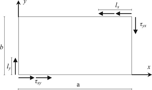
It is worth pointing out that, since structural elements are frequently subjected to in-plane partial loading and often prone to buckling, it is important that further design data should be provided to deal with this important stability problem. If such an issue has so far received relatively little attention from researchers, the reason for this is undoubtedly due to the additional analytical difficulties involved in obtaining rigorous solutions to the buckling of plates when subjected to partial loadings. Undeniably, the solution of this stability problem is mathematically difficult to obtain as the stress distribution throughout such plates varies considerably. However, using the finite element method, this varying stress system can be dealt with easily. Moreover, as can be seen from the above literature review, practically no research work has addressed this important issue. In the present work, the buckling of thin partially sheared plates (see ) is investigated using the finite element method. The aim of this article is to provide some representative linear and nonlinear critical shear buckling stress results for a simply supported plate for different applied shear ratios. Furthermore, linear and nonlinear compressive, shear and von Mises stress analyses are conducted. The numerical results obtained are summarized graphically and some important conclusions are drawn.
Fig. 1: Partially sheared rectangular thin plate
Research Questions and Gaps in Knowledge
Plates are the most important structural element used in engineering structures such as aircraft, bridges, ships and offshore structures. Rectangular thin plates are generally subjected to several types of in-plane loading including shear loading, which remains an important type of loading in plates. Consequently, in designing plates, it is vital that shear loading is given particular attention, otherwise it may lead to instability.
The aim of the research is to answer the following questions:
What is the effect of in-plane local shearing on the elastic and inelastic stability of plates?
How is it influenced by the dimensions of the plate?
Do the boundary conditions affect the stability and buckling of such plates?
In the last decades, many studies have been carried out to analyze linear buckling due to uniform shear for such structures. However, no study has been realised to evaluate the impact of local applied shear on the buckling of plates, although designers are always confronted with this issue.
In the present work, the linear and nonlinear buckling of thin locally sheared rectangular thin plates are investigated. The aim of the research is to show some representative linear and nonlinear buckling critical shear results for a simply supported plate. These results can be applied to airframes, where the action of the air loading on an aircraft wing is able to develop local shear loading that can lead to loss of stability. In addition, the aerodynamic heating of panels in supersonic aircraft can be approximated by local shearing stresses, as the temperature distribution is not uniform throughout the restrained plate.
Buckling Problem Formulation
The determination of the defection surface of a thin rectangular plate submitted to the action of shearing load Nxy applied uniformly along its edges requires the integration of the partial differential equations (4)–(6):
(1)
(1)
where w is the plate deflection and D the plate flexural rigidity with E and being the elastic constants and t the plate thickness.
In the analytic investigation of the stability of a uniform sheared plate, the derived critical shear buckling stress value is as follows:Citation5
(2)
(2) where k is the shear buckling coefficient and b the plate width. Depending on the boundary conditions, the k derived approximate expressions are
(3)
(3) However, when the shear distribution is not uniform, there is difficulty in solving the corresponding two-dimensional problem and determining the critical shearing buckling load.Citation35 Consequently, Eq. (2) is no longer applicable and a numerical method, such as FEM, should be used.
The critical buckling shear loads can then be worked out through the solution of an eigenvalue problem expressed as
(4)
(4) where K0 is the stiffness matrix corresponding to the base state, which includes the effects of the preloads, and Kσ is the geometric stiffness matrix, produced by the external in-plane shearing load vector
; the subscript i refers to the ith buckling mode, where the eigenvalues λi is the shearing load multiplier and
are the related buckling mode shapes (displacements). Thus, the critical buckling shear loads are given by
.
The stress vector of the plane stress problem is related to strain vector
by the well-known Hooke’s law:
(5)
(5) On the other hand, the plasticity calculation is performed by using the plane stress version of the von Mises yield function:Citation36,Citation37
(6)
(6) where σx, σy and τxy are the in-plane stress components.
Plate Modelling
Element Type and Capabilities
To carry out the present numerical buckling analysis of a thin rectangular plate subjected to partial in-plane shear, the commercially available finite element software ABAQUS CAE 2017Citation38,Citation39 is used. The numerical tests are performed by means of the eight noded quadrilateral thin element S8R5. This doubly-curved thin shell element has reduced integration points that provide economical solving time. Each node has five degrees of freedom that include three translations and two in-plane rotations. In the present study, a square finite element is used.
Specimen Selection
To select the plate ratio of a specimen on which the numerical tests of the present research will be performed, a set of plates with various parameters are analyzed. Indeed, a series of partially sheared thin rectangular plates with different aspect ratio values , ranging from 2 to 6, is analyzed to evaluate the effect of various loading aspect ratios α = (lx/a)% = (ly/b)%, ranging from 20% to 100%, on the critical shear buckling stress τcr.
The analyzed thin rectangular plate under partial distributed shear loading is shown in . lx and ly are distances over which the local applied shearing stress τxy extends in the x- and y-directions, respectively. a and b are the length and width of the examined plate, respectively.
The out-of-plane displacements are restrained along the plates four sides. In addition, the rotations are restraints in the y-direction along the plate length and in the x-direction along the plate width. The lateral restraints are applied at plate point (a, 0) in the x- and y-directions and at plate point (a, b) in the x-direction (see ).
The mechanical properties of the material used are as follows: Young’s modulus MPa and Poisson’s ratio ν = 0.3. The ultimate strength is taken equal to 400 MPa and the yielding strength is 250 MPa. The uniform plate thickness is taken as t = b/100.
Validation of the Finite Element Model
The results from the current study are validated using an analytical method based on the set of equations given above in the section titled “Buckling Problem Formulation”, namely Eq. (2) and Eq. (3).Citation7 Values of the critical buckling stress (τcr) are derived using these equations then compared with the values obtained from the finite element analysis of the current study for uniformly in-plane sheared plates. The comparative values are presented in below for a set of plate aspect ratios (β = a/b). The critical shear buckling values and the margins of error are also given. In the case where β = 2, the results obtained using different methods are in good agreement.
Table 1: Comparison between τcr values obtained analytically and those obtained in the present work
shows the variation of the linear critical shear buckling stress versus the load aspect ratio α for different plates aspect ratios β. As the β ratio increase from 2 to 6, it leads to a dramatic decrease of the plate critical shear buckling stress, and increasing the α ratio up to about 50% makes the plate more sensitive to buckling. Conversely, as the in-plane applied shear tends to be uniform, the plates show more stability. These findings demonstrate that, for plates with β = 2 and 3, increasing the applied shearing aspect ratio α from 20% up to uniform shear leads to a reduction of, respectively, 26.56% and 7.83% of the critical shear buckling stress.
Fig. 2: Variation of the linear critical shear buckling stress versus load aspect ratio α for different plate aspect ratios β
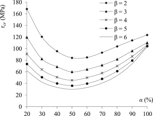
In the case of the long plates with β = 4, 5 and 6, the 20% sheared plates are more prone to buckling than those uniformly sheared as τcr increases with a values of, respectively, 17.02%, 41.64% and 66.82% (see ). The partially sheared long plates have a particular behavior in respect to buckling. As this last issue will be handled in future research, the present investigation deals exclusively with plate ratios β < 4.
Among the cases treated, the β = 2 plate gives relatively the best general insight of the plate buckling behavior. Consequently, this plate will be selected as a specimen for all numerical tests that will be performed in the present investigations.
Mesh Convergence Study
To find the more suitable plate model to be used in the present research, three different mesh patterns A, B and C are considered. For this purpose, the optimal value of the critical elastic buckling stress of a plate with β = 2 is analyzed under five load cases: α = 20%, 40%, 60%, 80% and 100%.
Using square elements, the A and B meshes are obtained with an increasingly tight uniform subdivision: (20 × 40) and (40 × 80) elements, respectively. On the other hand, the C mesh, which contains 8000 elements, is drawn by very tightly subdividing the area delimited transversely by the plate width and longitudinally by the loading extent. The remaining plate area is left relatively coarse. This model is examined to see if the problem is particularly located in the neighborhood of the applied loading.
The critical buckling stress is recorded for each mesh type. Associated with corresponding relative errors, these stresses are shown in . According to the results in this table, it clearly appears that a tight refined mesh leads undeniably to the sought optimal value. Similar results were achieved by Refs. [Citation40] and [Citation41]. However, the refinement in the neighborhood of the loaded edges led to little effect on the results. Therefore, the type B grid will be used in the numerical tests that will be conducted in the present buckling investigation.
Table 2: Critical linear buckling stress obtained from the different mesh discretizations
Results Presentation and Discussion
Buckling Mode Shape Patterns
As stated previously, the aim of the present investigation is to examine the buckling behavior of a mild steel plate subjected to in-plane patch shearing as depicted in . The finite element and the boundary conditions of the plate specimen used are described in the section titled “Specimen Selection”.
The first thirty mode shapes were examined, and the first four mode shapes were recorded. The numerical tests performed show that the plate, in its different mode shapes, always buckles symmetrically in its length direction. This plate behavior pattern reflects the applied load symmetry, the boundary conditions and the specimen’s relative longitudinal slenderness.
Linear and Nonlinear Critical Shear Buckling Stresses
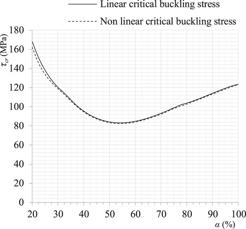
To examine the effect of partial shear loading on the critical shear buckling stress τcr, linear and nonlinear analyses were performed. Using Eurocode 3,Citation42 the steel material is bilinear elastic–plastic with yielding stress σy = 250 MPa and ultimate stress σu = 400 MPa. In both analyses, various load cases ranging from α = 20% to α = 100% with a load ratio increment of 1/40 in each analysis were treated. The results are depicted in , wherein the two curves of the critical shear buckling stress link up with the numerical results obtained for the plate specimen described in the section titled “Specimen Selection”.
Fig. 3: Variation of critical buckling load (linear and nonlinear) τcr versus α ratio for plate with β = 2
Specifically, the nonlinear equilibrium equations have been solved according to the iterative Newton–Raphson method under arc-length control with the Riks’ method algorithm.Citation43
In this method, for each load case, the critical shear buckling stress τcr is deduced from a curve where shear stress τxy is displayed against the maximum out of plane displacements wmax as shown in . In this figure, the graphs represent the shear stress variation of the plate specimen with a = 2000 mm and b = 1000 mm under five load cases ratios: α = 20%, 40%, 60%, 80%, and α = 100%.
Fig. 4: Variation of shear stress versus displacement wmax for plate with β = 2 and α = 20%, 40%, 60%, 80% and 100%
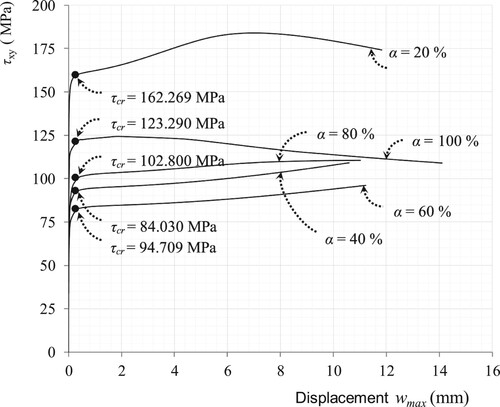
In nonlinear issues, buckling stress extraction is an essential tool for assessing the accuracy of the model used in analyzing the structural element behavior. Therefore, it is often necessary to obtain nonlinear static equilibrium solutions for unstable problems such as buckling. The bifurcation points are drawn in .
In the present study, the curves for linear and nonlinear buckling stresses show a similar global tendency that reveals the adequacy of the model used. These curves exhibit two common different significant sections with a minimum value for α = 55%:
Section (1) 20% ≤ α ≤ 55%. In this section, when α takes values between 20% and 40%, the linear and nonlinear curves show a dramatic τcr decrease. The high linear τcr value denotes the stabilizing effect of the very short distance over which the applied load acts. In this same section, when α takes values between 40% and 55%, even if the curves’ decrease is less dramatic, a little increase in the applied load extent still leads to a great plate buckling sensitivity.
Section (2) 55% ≤ α ≤ 100%. In this second section, as α increases up to one reaching then the uniform shear, the partially sheared plate is less prone to buckling. In this loading case, critical buckling stress values of 123.50 and 123.29 MPa are obtained in the linear and nonlinear analyses, respectively. The curves show that an increase of the applied loading ratio leads to a linear increase of τcr in both analyses with an average of 101.68 and 100.92 MPa in linear and nonlinear buckling analyses, respectively. These figures show the stabilizing effect of α on the buckling specimen.
Compressive and Shear Stress Analysis
As is well known, compressive stresses induce buckling. In the present work, the partially sheared plate compressive stress field was analyzed.
The stresses were recorded on the plate specimen described in the section titled “Specimen Selection”. The numerical tests were performed under a partial shear loading of 40%. The maximal and minimal values of compressive and shear stresses, σc max, σc min, τxy,max and τxy min, reached in linear and nonlinear analyses are summarized in .
Table 3: The compressive and shear stress values (σc max, σc min, τxy) for a plate with β = 2 and α = 40%
Linear Compressive Stress Analysis
The linear results recorded for the buckled plate specimen in the x- and y-directions show that the stress field exhibits a central symmetry resulting from the symmetrical applied loading.
In the x-direction, the compressive stress recorded stretches over 98% of the plate area with a very large value in comparison with the tensile one. This stress tendency is also observed in the y-direction, where the compressive stress occupies the major plate area. Furthermore, moving away from the loaded plate sides and following Saint Venant’s principle, the stress values decrease, reaching a constant value in the central area of the plate.
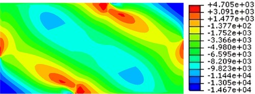
Moreover, the point where the applied shear loading stops is singular as the compressive stress in the two directions takes its maximal value at this point. These values are shown in . In the x- and y-directions, this compressive stress value decreases, by 14 and 15 times, respectively, towards the plate corners. In addition, the maximum and minimum values reached in the x-direction are 1.409 and 1.505 times those in the y-direction, respectively. These results denote significant compressive stress values in the long direction of the plate.
Nonlinear Compressive Stress Analysis
The nonlinear results recorded for the buckled plate specimen in the x- and y-directions show that the compressive stress distribution is symmetrical in both the x- and y-directions. These compressive stresses spread over more than 94% of the total plate area. The maximum compressive stress in the x- and y-directions shows almost the same value. Meanwhile, the minimum compressive stress value in the x-direction is 49.69% higher than that in the y-direction. As in the linear analysis, these noticeable values appear at the point where the applied shear loading ends.
It can be noticed from the results reached in the above analyses (see ) that the compression stress values recorded on the plate length direction are generally significant in comparison with those recorded on the width direction. As compressive stresses are always responsible for buckling, these results explain the plate buckling in the plate length direction.
Shear Stress Field Analysis
The shear stress distribution of the plate specimen described in the section titled “Specimen Selection” was also analyzed in the linear and nonlinear fields.
In the linear analysis, a symmetric shear stress distribution is observed and the maximal value of τxy = 128.9 MPa is recorded at the direct vicinity of the locally loaded edge of the specimen.
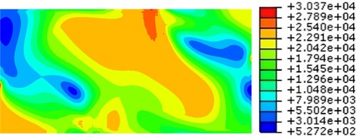
In the nonlinear field, before buckling occurs the shear stress is increased step by step. After buckling, the nonlinear shear stress reaches its maximum value of 146.7 MPa in the neighborhood of the applied loading stop point (see ). After this last step, the shear stress value is reduced to the value of τxy = 145.7 MPa.
Fig. 5: Nonlinear shear stress (10−2 MPa) distribution throughout a plate specimen with β = 2 and α = 40%
It is worth mentioning that, in the present nonlinear analysis, the diagonal field action phenomenon is clearly observed through . Indeed, before the plate reaches its theoretical buckling load, the shear stress can be resolved into diagonal tension and compression components as depicted in . Under continual raising of the applied shear force, the plate forms a diagonal field. In the case of uniform shear, this field is tensile since for thin plates the diagonal compression may be disregarded relative to diagonal tension values. In addition, the diagonal compression ceases to increase after buckling and any additional shear strength is carried by the diagonal tension action.Citation44
Fig. 6: Plate under shear loading and Fig. 7. Equivalent plate under shear loading
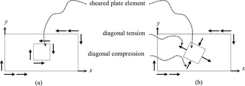
In the present case, the plate is compressed all over its area, thus the diagonal field action is compressive (see ) and, after buckling, all the stresses, shear, compressive and tensile, cease to increase.
Von Mises Stress Analysis
To get an insight into the plate buckling behavior beyond the elastic limit, a nonlinear von Mises stress analysis is performed. The numerical tests are held on the specimen described in the section titled “Specimen Selection” under a patch shear ratio of 40%.
In seeking the maximal von Mises stress settled in the plate, the intensity of the partial shearing applied on the buckled specimen is increased gradually and the recorded stresses are depicted in .
In the first step (see ), the buckled specimen exhibits plasticization at the plate length loading stop points. On the plate width, the plasticized areas are insignificant. Then, in the next steps, the increase of the applied shearing value leads to the increase of von Mises stress with the same plasticization areas. In the following step (see ), as the applied shearing value is increased, von Mises stress reaches its maximum value of 310.3 MPa without overtaking the ultimate strength value. Also, a diagonal stretching of the plasticization area is observed.
Fig. 8: Nonlinear von Mises stress (10−2 MPa) distribution at the first plasticization on a buckled plate specimen with β = 2, α = 40% and τxy = 94.709 MPa
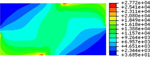
Fig. 9: Nonlinear maximum von Mises stress (10−2 MPa) distribution throughout a plate specimen value reached step with β = 2, α = 40% and τxy = 131.507 MPa
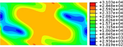
Finally, after reaching the maximum von Mises stress, decreasing the applied shearing loading leads to decreases in the von Mises stress value. Then the plasticization area expands diagonally and moves towards the plate width loading stop points as shown in .
Fig. 10: Nonlinear von Mises stress (10−2 MPa) distribution throughout a buckled plate specimen a few steps after reaching the maximum value with β = 2, α = 40% and τxy = 124.765 MPa
According to the above observations, no total collapse is recoded for the well-designed plate specimen and the material strength is thus used advantageously.
Discussion
Various methods were used to derive the critical buckling stress due to uniform in-plane shear applied to thin plates. Among these methods are the multi term extended Kantorovich method,Citation9 the finite difference methodCitation10 and the spline finite strip method.Citation11
An analytical solution was proposed in Ref. [Citation5] for specific boundary conditions, and the corresponding results are gathered in Ref. [Citation8]. In the present work, a comparative study is performed for the same boundary conditions on a set of plates having the dimension ratios a/b = 2, 3, 4, 5 and 6. Good agreement is observed between the proposed analytical results and the presented numerical critical buckling shear.
As stated previously, to the knowledge of the authors, no previous research work has addressed the buckling of thin rectangular plates subjected to in-plane shear applied locally. Through the present investigation, the following findings are achieved:
it appears that locally sheared long plates are more sensitive to buckling when subjected to local shearing as the critical shear stress
increases when the plate ratio decreases;
in addition, the set of tested plates with dimensions ratios a/b = 2, 3, 4, 5 and 6 show the same global tendency in respect of the critical buckling stress when the local shearing extent is growing and covering all the plate edges. Indeed, when the plate is sheared by up to 55% of its edges, it is prone to buckling more easily than when the applied shearing covers more than half of the plate edges;
also, the plates with a/b = 4, 5 and 6 are more sensitive to buckling when they are locally sheared than when the applied shear is uniformly distributed over their edges;
the same behavior is observed for short plates (a/b = 2 and 3). However, when loaded on 20% of their edges, these plates are less liable to buckle than when they are uniformly sheared.
The linear and nonlinear compressive, shear and von Mises stresses are recorded on a plate specimen with a/b = 2 under a local shearing of 40% of the plate edges:
the recorded compressive stress takes its maximum value at the point where the applied shear loading stops. This result highlights the fact that this point is singular. Thus, the designers must take into account the weakness of the plate at this point;
the significant compressive stress values recorded in the long direction of the plate clarify the occurrence of the buckling half waves in the plate length direction;
in the shear stress analysis, the diagonal field action is clearly observed. As the plate is compressed all over its area, this phenomenon is compressive instead of being tensile, as in the case of applied uniform shear;
in the nonlinear von Mises’ stress analysis, the buckled specimen exhibits plasticization at the singular points on the plate length. As the applied shearing value increases, the von Mises stress reaches its maximum value without reaching the ultimate strength value. The decrease of the applied shear value leads to a diagonal expansion of the plasticization area that moves towards the singular points on the plate width. No total collapse is recorded for the well-designed plate specimen and the material strength is thus used advantageously.
Conclusions
In the present article, the buckling of patch sheared thin plates has been investigated numerically in linear and nonlinear fields. The aim of this work was to provide some representative results that could be used in tackling such issues. The plate specimen used in all numerical experimentations has been judiciously designed by assigning it the optimal finite element grid and the most appropriate plate ratio. The findings may be summarized as follows:
the effect of applied partial loading on the critical shear buckling stress investigation has shown that the stability effect of the load ratio on the plate specimen is reached when the load extent covers 55% of the plate sides;
plate buckling in the length direction was justified by the significant compressive stress values recorded in this direction. The occurrence of the waved plate length is due to the Poisson’s effect induced by the settled compressive stresses. By examining the shear stress field, it has been shown that at buckling a compressive diagonal field action occurs, and at post-buckling, the stresses remain constant;
the von Mises analysis showed that plasticization occurs at the plate length loading stop points. Furthermore, in the same analysis, after reaching the maximum von Mises stress, the decrease of the applied patch shear revealed diagonal expansion of the plasticization area and made this latter move towards the plate width loading stop points without reaching total collapse, making the material use advantageous;
future research could investigate the behavior of partially sheared long strips and undertake experimental work in order to validate the results obtained in the present research.
Recommendations
Implications of the Findings in Practice
The present research provided an insight into, and understanding of, the buckling behavior of thin rectangular plate subjected to partial in-plane shear. In taking into account simultaneously the plate and the loading ratios, the designer is able to predict the stability loss of short plates as well as structural strip elements. Again, the knowledge of the weak plate point locations allows the engineering structural designer to prevent the element from collapse.
The findings are useful in the design of structures or structural elements where local shearing is present. Examples include the design of the wings of aircraft or the hulls of ships where local shear loading could lead to loss of stability. Another example is in the design of panels in supersonic aircraft where the aerodynamic heating is approximated by local shearing stresses since the temperature is not uniformly distributed throughout the restrained plate.
Implications of the Findings on the FE Modelling of Rectangular Plates
In the present work, the authors investigated the optimal grid pattern that can be used in the analysis of the buckling of rectangular plates subjected to local in-plane shear. Different boundary conditions were considered and analyzed. Plate modeling was created by means of an eight noded isoparametric thin element. The grid pattern was designed to satisfy good accuracy with low density. A convergence study was performed through two meshes uniformly subdivided using square elements and one mesh locally refined in a judicious way. In seeking the critical buckling shear stress, good results were obtained by using a second uniform grid. The model developed by the authors is a very useful tool for both designer and modelers of these structures.
Data Availability Statement
The data that support the findings of this study are available from the first named author, upon reasonable request. Any such requests should be made by emailing the first named author directly.
Disclosure Statement
No potential conflict of interest was reported by the authors.
Correction Statement
This article has been corrected with minor changes. These changes do not impact the academic content of the article.
References
- Bernoulli JI. Essai théorique sur les vibrations des plaques élastiques, rectangulaires et libres. Nova Acta Acad. Sci. Imp. Petrop. 1789;5:197–219.
- Navier C. Bulletin des Sciences de la Société Philomathique de Paris. In Paris. 1823.
- Kirchhoff G. Über das Gleichgewicht und die Bewegung einer elastischen Scheibe. Journal für die reine und angewandte Mathematik (Crelles Journal). 1850;40:51–88.
- Southwell RV, Skan SW. On the stability under shearing forces of a flat elastic strip. Proc. Math. Phys. 1924;105(733):582–607.
- Stein M, Neff J. Buckling stresses of simply supported rectangular flat plates in shear. In. National Aeronautics and Space Admin Langley Research Centre, Hampton, VA: National Advisory Committee Buckling For Aeronautics. 1974.
- Budiansky B, Connor RW, Stein M, Field, V. Buckling in S-AR of continuous flat-plates, 1948.
- Timoshenko, S, Gere, J. Theory of Elastic Stability. New York: McGraw-Hill, 1961.
- Bulson PS. The Stability of Flat Plates. California: Elsevier Publishing Company. 1969.
- Shufrin I, Eisenberger M. Shear buckling of thin plates with constant in-plane stresses. Int J Struct Stab Dyn. 2007;7(2):179–192. doi:10.1142/S021945540700223X
- Husain HM, Ammash HK. Shear buckling behavior of rectangular thin plate with variable thickness. Al-Qadisiyah J. Eng.Sci. 2009;2(3):542–552.
- Pham CH. Shear buckling of plates and thin-walled channel sections with holes. J Constr Steel Res. 2017;128:800–811. doi:10.1016/j.jcsr.2016.10.013
- Zhong H, Pan C, Yu H. Buckling analysis of shear deformable plates using the quadrature element method. Appl Math Model. 2011;35(10):5059–5074. doi:10.1016/j.apm.2011.04.030
- Leblouba M, Junaid MT, Barakat S, Altoubat S, Maalej M. Shear buckling and stress distribution in trapezoidal web corrugated steel beams. Thin-Walled Struct. 2017;113:13–26. doi:10.1016/j.tws.2017.01.002
- Guo T, Sause R. Analysis of local elastic shear buckling of trapezoidal corrugated steel webs. J Constr Steel Res. 2014;102:59–71. doi:10.1016/j.jcsr.2014.06.006
- Alinia M. A study into optimization of stiffeners in plates subjected to shear loading. Thin-Walled Struct. 2005;43(5):845–860. doi:10.1016/j.tws.2004.10.008
- Vu, Q-V, Papazafeiropoulos G, Graciano, C, Kim, S-E. Optimum linear buckling analysis of longitudinally multi-stiffened steel plates subjected to combined bending and shear. Thin-Walled Struct. 2019;136:235–245. doi:10.1016/j.tws.2018.12.008
- Alinia M, Dastfan M. Behaviour of thin steel plate shear walls regarding frame members. J Constr Steel Res. 2006;62(7):730–738. doi:10.1016/j.jcsr.2005.11.007
- Paik JK. Ultimate strength of perforated steel plates under combined biaxial compression and edge shear loads. Thin-Walled Struct. 2008;46(2):207–213. doi:10.1016/j.tws.2007.07.010
- Yi J, Gil H, Youm K, Lee H. Interactive shear buckling behavior of trapezoidally corrugated steel webs. Eng Struct. 2008;30(6):1659–1666. doi:10.1016/j.engstruct.2007.11.009
- Gendy BL. Critical shear buckling load of tapered plate with circular opening. HBRC Journal. 2016;12(3):296–304. doi:10.1016/j.hbrcj.2014.12.009
- Brighenti R, Carpinteri A. Buckling and fracture behaviour of cracked thin plates under shear loading. Mater Des. 2011;32(3):1347–1355. doi:10.1016/j.matdes.2010.09.018
- Chen B, Sivakumaran K. Post-buckling shear strength of thin steel plates. Procedia Eng. 2011;14:641–647. doi:10.1016/j.proeng.2011.07.081
- Ahn J-H, Kainuma S, Kim I-T. Shear buckling strengths and post-buckling behaviors of steel webs with local corrosion. Journal of JSCE. 2013:1:251–261.
- Amani M, Rafeei B, Alinia M. Shear buckling and ultimate capacity of steel plates coupled with cover panels. J Constr Steel Res. 2013;80:181–187. doi:10.1016/j.jcsr.2012.08.002
- Hassanein M, Kharoob O. Behavior of bridge girders with corrugated webs: (I) real boundary condition at the juncture of the web and flanges. Eng Struct. 2013;57:554–564. doi:10.1016/j.engstruct.2013.03.004
- Hassanein M, Kharoob O. Shear buckling behavior of tapered bridge girders with steel corrugated webs. Eng Struct. 2014;74:157–169. doi:10.1016/j.engstruct.2014.05.021
- Aggarwal K, Wu S, Papangelis J. Finite element analysis of local shear buckling in corrugated web beams. Eng Struct. 2018;162:37–50. doi:10.1016/j.engstruct.2018.01.016
- Riahi F, Behravesh A, Fard MY, Armaghani A. Buckling stability assessment of plates with various boundary conditions under normal and shear stresses. Engineering, Technology & Applied Science Research. 2017;7(5):2056–2061. doi:10.48084/etasr.1516
- CEN Eurocode 3 Design of steel structures—Part 1–5 Plated structural elements. In. CEN Brussels, Belgium, 2006.
- Ceranic A, Bendic M, Kovacevic S, Salatic R, Markovic N. Influence of patch load length on strengthening effect in steel plate girders. J Constr Steel Res. 2022;195:107348. doi:10.1016/j.jcsr.2022.107348
- Kovacevic S, Ceranic A, Markovic N. Patch load resistance of longitudinally stiffened steel plate girders: A parametric study. ce/Papers. 2021;4:2107–2114. doi:10.1002/cepa.1528
- Huang S, Qiao P. Buckling of partially-compressed laminated composite plates. Thin-Walled Struct. 2021;169(3):108385. doi:10.1016/j.tws.2021.108385.
- Hou J, Guo S, Gao S, Chen J, Xu H. Out-plane interaction behavior of partially buckling-restrained steel plate shear walls. Thin-Walled Struct. 2023;183(7):110352. doi:10.1016/j.tws.2022.110352.
- Lapira L, Gardener L, Ahmer Wadeee M. Elastic local buckling formulae for thin-walled I-sections subjected to shear and direct stresses. Thin-Walled Struct. 2023;182:110150. doi:10.1016/j.tws.2022.110150.
- Timoshenko, S.P., Goodier, J.N. Theory of elasticity, 1951.
- Mises RY. Mechanik der plastischen Formänderung von Kristallen. ZAMM – Zeitschrift für Angewandte Mathematik und Mechanik. 1928:8(3):161–185. doi:10.1002/zamm.19280080302
- Mises RY. Mechanik der festen Körper im plastisch-deformablen Zustand. Nachrichten von der Gesellschaft der Wissenschaften zu Göttingen, Mathematisch-Physikalische Klasse. 1913;4:582–592.
- Systemes D. ABAQUS analysis user’s manual version 2016. In. Waltham, MA, 2016.
- Hibbitt H, Karlsson B, Sorensen P. Abaqus user’s manuals, release 2017. Dassault Systèmes, 2017.
- Kilardj M, Ikhenazen G, Messager T, Kanit T. Linear and nonlinear buckling analysis of a locally stretched plate. J Mech Sci Technol. 2016;30(8):3607–3613. doi:10.1007/s12206-016-0721-5
- Ikhenazen G, Saidani M, Kilardj M. Optimization of a finite element mesh for plates subjected to in-plane patch loading. J Mech Sci Technol. 2019;33(3):1185–1193. doi:10.1007/s12206-019-0218-0
- EN 1993-1-5. Eurocode 3. Design of steel structures – Part 1–5: plated structural elements, CEN. 2017.
- Riks E. An incremental approach to the solution of snapping and buckling problems. Int J Solids Struct. 1979;15(7):529–551. doi:10.1016/0020-7683(79)90081-7
- Wagner H. Flat sheet metal girder with very thin metal web (Tech Memorandum Nos. 604-606). N.A.C.A (1931).