
 ?Mathematical formulae have been encoded as MathML and are displayed in this HTML version using MathJax in order to improve their display. Uncheck the box to turn MathJax off. This feature requires Javascript. Click on a formula to zoom.
Abstract
The paper pulp tank in Valkeakoski, Finland, collapsed on 27 March 1996. The volume and height of the steel tank was 6000 m3 and 35.5 m, respectively. The collapse occurred during test filling with water. During the test filling it was noticed that the tank was tilting. The time from first observation to final collapse was around 12 min. The tank collapsed onto a building next to it, causing the death of one person. During the collapse there was approximately 5000 m3 of water inside the paper pulp tank. The ambient temperature was −20°C during the collapse. The Safety Investigation Authority started an investigation because the incident was a major accident and there was loss of human life. Several reasons for the collapse were discovered. In addition, several recommendations were made for construction in general. This article presents a case study and details based on material that has already been published, but it also includes a structural analysis made in the study. The goal was to clarify the main reasons and form them into a timeline of the collapse. Also, lessons learnt are presented.
Introduction
Paper pulp is often stored in steel tanks in paper mills. The volume of such tanks ranges typically from 2000 to 10,000 m3. The pulp’s density is around 1.0. The tanks’ geometry is often designed so that the cylinder’s diameter is smaller at the bottom part of the tank for pulp processing reasons. The tanks are filled with water before actual use in order to guarantee the tightness of the structure.
The collapse at Valkeakoski occurred during test filling. The building next to the tank housed the factory’s repair shop and social facilities. The tank tilted and fell on that building. The accident caused one casualty, who was inside the building during the incident. Several other buildings were damaged within a 100 m radius from the spot where the tank fell at the factory site, because the 5000 m3 of water inside the tank caused an intensive flood wave.Citation1
Investigation Process
The Finnish Safety Investigation Authority launched an investigation. It appeared that the collapse would have caused many more casualties had the time or direction of the fall been different. Hence, the collapse had the potential of being a major accident as defined by law. For this reason, the Ministry of Justice set up a board of inquiry to investigate the collapse.Citation1
The board was assembled on 2 April 1996. Before that, the individual board members attended the site in the days following the collapse. The board as a whole continued to meet at the site from 3 April onwards.Citation1
During their work, the board consulted experts from different fields. These experts conducted studies that dealt with:
The board prepared a reportCitation1 about the accident. During the process, the board interviewed and requested statements from the various parties involved and from experts in the field of structural engineering. The final report, from 1998, includes reasons for the collapse and recommendations for civil engineering practice.Citation1
A legal process was begun after the collapse, but in 2000 the local prosecutor in city of Valkeakoski decided that there was no cause to launch a criminal investigation, based on the report of the investigation board and expert statementsCitation1–7 that were ordered by the structural designer of the foundations.Citation8 This decision was made despite the proven existence of deficiencies in the structures, because it was impossible to identify clearly one actual main reason for the accident.Citation9 There was also a lack of design guidance at that time.
Structures
The cover of the tank was made of steel. It stood on a concrete base slab with a thickness of 1.5–2.1 m. The side view of the structure and Detail A (DET A) are shown in .
Fig. 1: Side view of the structure and DET A. Dimensions in millimetres. The data for the Figure is obtained from Refs. [Citation1,Citation12]
![Fig. 1: Side view of the structure and DET A. Dimensions in millimetres. The data for the Figure is obtained from Refs. [Citation1,Citation12]](/cms/asset/3155b7b4-51b4-4d67-b80f-f9b146f4fc5f/tsei_a_2282453_f0001_oc.jpg)
The total height from the bottom of the base slab to the top part of the actual tank was 37.55 m. The tank was welded from curved steel plates partially on site. The thicknesses of the steel plates are shown in . The welding between the steel parts was done on site, including the connection of the supporting steel ring, part 5, outside connected plates 4 and 6.Citation1
A plan view and section of the base plate, together with the connection to the steel tank, is shown in . The tank was connected to the base plate with 24 steel bars having diameter 45 mm and a total length of 1250 mm. The yield strength of the steel bars was 355 MPa. The bars were grouted into ducts with a diameter of 290 mm and a total length of 800 mm and cast into the base plate concrete. The thickness of grouting between the end plate of the tank and base plate concrete was 80 mm.Citation10
Fig. 2: Plan and section of the base plate. Dimensions in millimetres. The data for the Figure is obtained from Ref. [Citation1]
![Fig. 2: Plan and section of the base plate. Dimensions in millimetres. The data for the Figure is obtained from Ref. [Citation1]](/cms/asset/9387e43e-9431-496e-a640-d75a0f6bd8ab/tsei_a_2282453_f0002_oc.jpg)
The thickness of the base slab was 1450 mm at the edge, 1550 mm next to the inner ring and 2100 mm below the tank’s steel ring. The concrete grade was C25/30 and the reinforcement steel grade was B500B. The structure was conducted without shear reinforcement. Bending reinforcement at the bottom was 25 #150 and 16 #250 at the top of the base slab. The concrete cover was 50 mm at each side. Hence, the effective depth of the foundation plate outside the steel tank was 1.42 m.Citation11
The base slab was founded on 12 steel pipe piles with a diameter of 508 mm and a wall thickness of 12.5 mm. The yield strength of the steel was 355 MPa. The piles were of steel–concrete composite structure, as they were filled with reinforced concrete. Reinforcement inside the piles consisted of 10 pcs of 32 mm rebar made from steel of grade B500B. The piles were designed as end bearing piles and monolithically connected to the base plate.Citation1,Citation11
The piles were driven by hammering. Based on ground investigations, the tight layer of soil or upper layer of ground rock was approximately 5.4 m from the bottom of the base slab. However, the actual lengths of the piles amounted to 4.5 m.Citation1,Citation6
The Collapse
Observations During the Collapse
The following stages before and during the collapse were observed:
25.3.1996 13:45 test filling with water started;
26.3.1996 16:30 2440 m3 of water had been pumped into the steel tank;
27.3.1996 07:00 4075 m3 of water had been pumped into the steel tank;
27.3.1996 13:00 4620 m3 of water had been pumped into the steel tank;
27.3.1996 13:00 filling was suspended because of pump failure;
27.3.1996 16:00 filling was restarted after pump failure;
27.3.1996 ∼20:45 beginning of final stages of the collapse;
– personnel of the test filling heard an unusual noise from the tank;
– a gap of approximately 0.5–1.0 m between the stair tower and maintenance bridge at the roof of the steel tank was observed;
– a gap of 5 cm between the circular part of the base slab and the surface layer of the yard was observed towards the direction where the tank later fell. The observation was that the displacement had been transversal;
– a connection pipe from the base of the lower part of the steel tank was bent; the pipe was at the side where the gaps were observed;
27.3.1996 ∼20:50 filling was stopped because the tank had tilted; approximately 5055 m3 of water had been pumped into the steel tank, with a filling ratio of 84%; the water level was ∼31 m from the base;
27.3.1996 ∼20:50–20:57
– the tilting initially progressed slowly, and it accelerated towards the end;
– at the start of the fall, a machine-gun-like noise was heard;
– immediately after the noise, the tank fell onto the building next to it;
– the fire and rescue services received an automatic alarm at 20:57.Citation1
The collapse was a large-scale one. The maintenance building was partly crushed. The cable and pipeline structures were crushed. The water wave inflicted damage within a 100 m radius of the tank. An aerial view of the collapsed tank is shown in .
Fig. 3: The tank after collapse:Citation5 (1) steel plate 5; (2) buckling of bottom part of the cone; (3) bar connection to the steel tank; (4) connection bars at the base slab
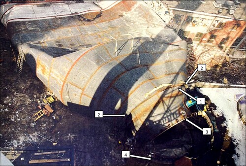
The pulp tank fell onto the maintenance building, which can be seen at the top right of . The bottom part of the steel tank had been torn off from its foundation. The wave damaged several buildings, cars and the gas bottle warehouse, spreading 60 gas bottles around the site. The roof of the steel tank fell 100 m from the tank. The paper mill was shut down for two weeks.Citation1
Structural Survey
Base Plate
An internal and thicker part of the base plate was tilted towards the direction of the fall of the tank, see . Also, the connection between the steel tank and the foundation was broken during the collapse.Citation4
Fig. 4: Tilted internal part of the base plate:Citation4 (4) connection bars at the base slab; (5) inner part of the base slab; (6) outer parts of the base slab
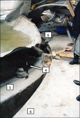
It can also be observed that the internal part of the base plate had punched through the outer part of the base plate. It was assumed that the machine-gun-like noise during the last stage of the collapse had come from the connection bars coming loose from their connection.Citation1
The condition of the base plate after dismantling the steel tank and excavation of the soil is shown in . The tilted internal part of the base plate is clearly visible.
Fig. 5: The base plate after the collapse; the direction of the fall to the left (red arrow).Citation4 (4) Connection bars at the base slab; (5) inner part of the base slab; (6) outer part of the base slab
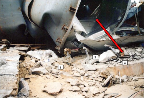
The outer part of the foundation had been crushed into parts. The fracture lines and direction of the fall are depicted later together with results in . It was observed that the circular failure surface next to the inner part of the base slab was approximately inclined outwards in a 45° angle. It was not possible to observe the exact failure surfaces because of the dismantling technique of the base slab.Citation6
Piles
The length of the designed piles was 5 m. Piles 1, 4, 9 and 12 had been designed to be vertical. The designed inclination of the other piles was 5:1. The realised geometry of the pile group is shown in and .Citation6
Fig. 7: The actual geometry of the pile group from the 3D geometry of the pile group (top view)
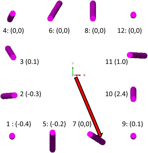
Table 1: Pile groupCitation6 geometrical data
gives the piles’ inclination as n:1, the direction of inclination as clockwise, the length as L and the offset of the tip of the pile from the firm rock surface as dZ. A positive value of dZ means that the pile tip had not reached the firm rock surface.
The actual firm rock surface was defined when the foundation was rebuilt. During the installation of bored cast-in-place piles, it was also observed that the uppermost 0.5 m layer of rock was not firm, and it was removed during the erection of the piles. The actual geometry of the pile groupCitation6 and values of dZ are shown in from the top view of the 3D geometry of the pile group.
Most probably, the tips of piles 10 and 11 had not reached the firm rock surface. Pile 10, in particular, was very short. That indicates that this pile had not reached the firm rock surface.Citation6 Overall, the inclinations and directions of inclination varied a lot from the designed ones.
The length and inclination of piles 6 and 8 were quite close to the designed ones. It was reported that, during the piling of these piles, boulders had been mined from the soil layers before final piling because the piles did not penetrate into the ground during the first piling attempt. The excavation was filled with gravel.Citation6 The inclinations of piles 5 and 7 are more vertical than the designed ones, and the inclination of pile 10 is in the Y-direction rather than the designed X-direction. This would have caused an unintended horizontal force component in the negative Y-direction.
Overall, it was concluded that piles 1, 2, 3, 7 and 9 most probably reached the firm rock surface, whereas piles 10 and 11 did not. No clear conclusion was made regarding piles 4, 5, 6, 8 and 12. The piles were lifted after the collapse and dismantling of the base slab. The tips of the piles were examined after lifting. Based on these, the same conclusion was reached: that not all piles had properly penetrated the firm rock surface.Citation6
The construction of the pulp tank was part of a larger project. The foundations for the paper machines were also constructed with similar steel pipe piles. A dynamic load test with pile driving analysis had been carried out for six of those piles. A piling machine with a free-fall 6000 kg hammer with a 0.85 m drop height had been used. The result was that the estimated pile break load was between 2.7 and 3.0 MN without a safety factor, which was around 2.0–3.0 at that time.Citation6
The same piling machine was used for driving the piles for the pulp tank. The loads of the piles in the pulp tank foundation were on a magnitude of 9 MN, see . Had the piling machine been hydraulically accelerated with a 6000 kg hammer, the maximum break load would have been 5.8 MN without the safety factors. Hence, it was revealed that the machine was too small for piling, and it would not have been possible to obtain the required capacities for the foundation of the pulp tank. There was no proper geotechnical design for pile capacities, and the documentation during the piling work was also discovered to be false.Citation6
Table 3: The support reactions Z of the pile tips
Steel Tank
The steel tank assemblies were welded together on site. The construction had been made during winter, when sub-zero temperatures are common. The bottom weld of plate 5 has been done upwards due to the connection geometry, see . This had been a demanding task due to on-site conditions.Citation5,Citation12
After the collapse, the welds were examined. The designed fillet weld dimension was 24 mm in the connections of plate 5. It was found that the average fillet weld dimension for the bottom weld was 15.2 mm, with a minimum of 11.7 mm. The top weld average was 15.6 mm, with a minimum of 9.6 mm. The measured values are clearly smaller than the designed values of 24 mm.Citation5 The measurement results are shown in .
Table 2: Measured weld dimensions from plate 5Citation5
The values are shown clockwise, with the direction of the fall being zero degrees. There is an x-marker if the weld has been found to have broken during the fall. It was reported that the welds had most probably been broken owing to the bending of the weld.Citation5 This indicates that the breaking of the welds took place after the start of the fall.
Structural Analysis
A structural analysis was carried out in order to find out the first stages of the collapse. This study does not cover the final stages of the collapse in order to simplify the structural models and avoid convergence problems. The original investigation included separate analyses of the steel tank, the foundation plate and the foundation piles. However, there was no structural analysis or model of the whole structure. A model of the whole structure was formulated during this study because it was assumed that this might reveal new aspects of the behaviour of the structure.
A nonlinear finite element model was formulated with LUSAS Bridge Plus software.Citation13 The steel tank and foundation slab are modelled with shell elements (QTS8). The piles are modelled with beam elements (BMI21). A view of the model and a global orthogonal coordinate system is shown together with first results in .
The modelling plane of the base slab is set near the assumed compression chord of the base slab to account for the effect of the inclined piles on the reinforcement stresses in a proper way with an analysis of the shell element. The shell element would not result in a right bending moment without taking separate account of the horizontal component of a normal force from the inclined pile, which affects the bending moments of the base slab.
The connection between the steel tank and the base slab is modelled by extending the steel tank up to the modelling plane of the base slab.
The realised geometry of the piles was clearly different from the designed geometry. The top and bottom ends of the piles are modelled based on measurements during the piling and after the collapse, see and . Imperfections of the steel shells were not accounted for because it was concluded that these did not take place during the first stages of the collapse.Citation5
Loads
A gravity load is assigned to structural elements. The gravity load of steel plates is set with a density of 8.0 in order to take into account the non-structural filling inside the steel tank. This is done in a simplified manner because it is assumed that the self-weight of the structures played a minor role when compared to total loads. The total gravity load of the self-weight is 8.5 MN.
The water pressure is given by the local element z-coordinate (out of plane) which increases with the global z-coordinate. The load is transferred to the steel plates of the tank and to the base slab inside the steel tank. The analysis is carried out so that the load will follow the deformed direction of the local z-coordinate. Based on the investigation, the volume of water was 5055 m3. This would lead to a water level of 29.5–30.0 m from the top of the base slab. Therefore, the total gravity load of the water was 59 MN.
As it was reported that the wind was very mild during the collapse, it is not considered as a factor. Neither is a temperature load considered, because it is assumed that it did not have a significant effect on the results.
Material Properties
The steel material is treated as linear elastic. After the analysis, it was confirmed that the steel stress was clearly below yielding. The material for the piles is also treated as linear elastic, taking into account a composite section of the reinforced concrete and steel pipe pile.
The material for the base slab is modelled with nonlinear material properties because it clearly underwent plastic deformation before the collapse. Shell elements are used for the reinforced concrete slab and simplifications of the material properties are used. First, a relationship between the bending moment (M) and curvature (κ) is created. The reinforcement ratio of the base slab was low, 0.21% for the outer part of the base slab and 0.16% for the inner part. The effective depth at the outer part was 1.42 m. The M–κ curve without taking account of tension stiffening is shown as red and with tension stiffening as blue in .
Fig. 8: The M–κ curve of the outer part of the base slab
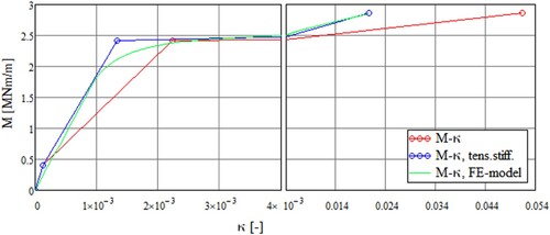
The M–κ curve is well known and used here in a simplified manner with classical bending theory. Tension stiffening is considered using the tension chord model from Ref. [Citation14]. Points for the cracking moment, yield moment and break moment are considered.
The concrete material is treated with the stress block assumption.Citation15 The properties of reinforcement were tested during the investigation. The mean value of the yield stress was 550 MPa,Citation2 which was used in the analysis. The elastic modulus was assumed to have a value of 205 GPa.
The green curve in shows the modelled M–κ relationship in the FE model. It has been created by giving the material elastic–plastic hardening material properties for the slab so that it will produce the red M–κ curve. The model is not capable of predicting a decreasing moment branch. It is known that the von Mises yield criterion cannot be fully compatible with the normal moment yield criterionCitation16 of the concrete slab, especially since accounting for the torsional component mxy of the slab leads to different results. In this study, it was seen that the component mxy (mrt in circular coordinates) was relatively mild next to the circular steel tank connection, where high bending moments occurred. It was accepted that this kind of model was good enough for the purpose of this study. During the work, comparative results were obtained using a linear-elastic model based on the M–κ curve of the yield moment to confirm that the moments were at the right level.
Boundary Conditions
The soil layers at the site are shown in . There was a three-metre layer of clay under the base slab. Its dry density was 16.5 kN/m3 and cohesive strength 30 kN/m2. The modulus of the subgrade reaction can be found from the following equations for rectangular foundation,Citation17 and the modulus of the soil is defined based on Ref. [Citation18]:
(1)
(1) where
, b = width of base slab,
and
closed shear strength, see .
This yields a modulus of subgrade reaction of 1.5 MN/m3. However, the effective soil thickness tfound yields 3 m, which is almost the same as the distance from the bottom of the base slab to the upper surface of the moraine layer. Hence, the actual value would be higher than Eq. (1) yields. Furthermore, the soil would yield during the failure and creep between the first and second day, especially if stresses were high. At the edge of piles 6 and 8, boulders were mined and gravel fill was conducted. Moreover, the soft soil layer was thicker at the opposite side. Based on all this, the value of the modulus of the subgrade reaction 1.5 MN/m3 was used at the middle of the foundation. The value was linearly interpolated so that it was 1.5 times at the edge of piles 6 and 8 and 0.5 times at the opposite edge of the foundation.
The modulus of lateral subgrade reaction ku, ultimate line reaction qu and for the piles are defined according to Ref. [Citation18]:
(2)
(2) where D = pile diameter. ku and qu yield values of 1.5 and 0.09 MN/m, respectively. Based on these values, the displacement yu achieving full lateral soil strength would be 9/50D, which is 0.15 m with a pile diameter 0.508 m.
The pile tips were mainly supported with rigid supports for transitional directions. Pile 10 was supported with a spring support in an axial direction. This was done because it was observed that the length of the pile was very short, and it was observed during the dismantling of the foundation that pile 10 lifted very easily compared to the other piles. It was concluded in Ref. [Citation6] that the pile had not reached the firm rock surface at all, as can be seen from . There was no pile driving data available to estimate the stiffness of the pile tip in an axial direction. Without leaving the tip of pile 10 unsupported, a soft 20 MN/m spring was used in the FE-model.
The foundation had been built above the clay layer. The fill around the foundation was done above the clay layer. This have led to a situation in which the lateral stiffness was affected by the properties of the clay. Also, the filling itself was found to be the loose, with a density of 18 kN/m3.Citation6 Based on this information, it was assumed that a passive soil pressure would become active after a displacement yu of 5% of height of the foundation, because the soil was loose above the clay layer. It was also assumed that half of the passive soil pressure would take place at one fourth of yu.Citation19 This yielded a value of 2.7 MN/m2 for the lateral modulus of subgrade reaction.
It is acknowledged that the soil properties included many uncertainties. They have been assigned based on the available simple models in the literature. Also, the models were found be valid for typical Finnish soils. However, what the actual soil characteristics were, and how the piles were actually supported, cannot be exactly solved with the data available. This was also the reason for the soil not being modelled with 3D elements, i.e. because it was assumed that it would not provide a new value for this study.
Punching Shear Capacity
A punching shear capacity is assessed using the critical shear crack theory (CSCT), which has been improved in recent years.Citation20–23 CSCT connects strains of bending reinforcement to the available capacity with a failure criterion. Once the capacity is reached, the load–rotation curve reaches the failure criterion.
The shear slenderness based on pile locations from the inner portion of the slab varies from 1.0 to 2.3, see . The failure criterion that yields mean values from test results can be found in Ref. [Citation21]. This gives a punching shear stress capacity for height at an effective depth of 0.74–1.39 MPa (for varying shear slenderness) when the bending reinforcement is yielding and if an aggregate upper sieve of 32 mm is assumed. The control section is half of the effective depth from the support. The capacity is 0.97–1.72 MPa if the bending moment is 80% from yielding.
A characteristic value of the punching shear capacity with additional factors, like when the shift between one-way shear and punching shear has been accounted for, can be found from Refs. [Citation22,Citation23]. This gives a capacity of 0.81–0.93 MPa when partial safety factors are not accounted for.
Results
The deformed mesh of the FE model under a load like that during the collapse is shown on . The values of displacements in the X-direction are highlighted. There are also transitional displacements. This confirms that the observation during the collapse was valid. During the original forensic investigation, this observation was questioned.
Fig. 9: The deformed mesh and geometry of the tank in the FE model. The deformations are magnified 50-fold. The displacements in the X-direction (m) are highlighted, and the stresses (kN/m2) along the vertical local axis (Sx) of the steel shells, the bottom cylinder, and the conical cylinder are shown with stress contours
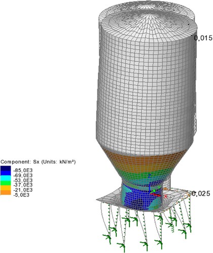
The tank tilted almost towards the X-direction (clockwise at 4 p.m.). The tilt was relatively small compared to the deformations that were observed before the collapse. There are two probable reasons for this. First, the model is incapable of solving the descending branch of the moment near the failure of the slab. Secondly, and probably most significantly, punching shear failure is not included in the model.
Regarding the issue of bending, a utility ratio related to yielding of the reinforcement in a radial direction for the forces causing tension in the bottom of the base slab (Mr.bot) is shown in . The loads are at the stage of the collapse.
Fig. 6: The utility ratio for radial bending related to yielding of the bottom reinforcement
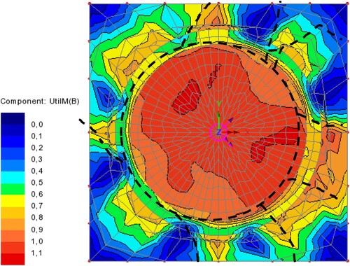
The result shows that the moments were clearly above yielding, almost at bending failure. The fracture lines from the top of the base slab, which were documented during the original forensic investigation, are drawn above the result. The result extracted from the model fits those observations very well. This also indicates that pile 10 had not been on a firm rock surface, because the bending moment above pile 10 also fits well with the observations of the fracture lines. Furthermore, it was found that the moments at the inner and thicker part of the base slab are clearly increased when compared to the designed pile group geometry.
The shear stresses are compared to the punching shear resistance. shows the shear stresses t.rz on a perimeter of d/2 distance within a radius of 4.8 m from the centre, perimeter u1 in Refs. [Citation21–23], a running average t.rz.sm of the shear stress t.rz.mean along length of 3d on the perimeter, a mean shear stress along the whole perimeter and a range of capacities 0,74-1,39 MPa when the bending reinforcement had reached the yielding phase.
Fig. 10: Shear stresses from the model, τrz, smoothed from the model τrz.sm, mean shear stress τrz.mean, and the range of capacities
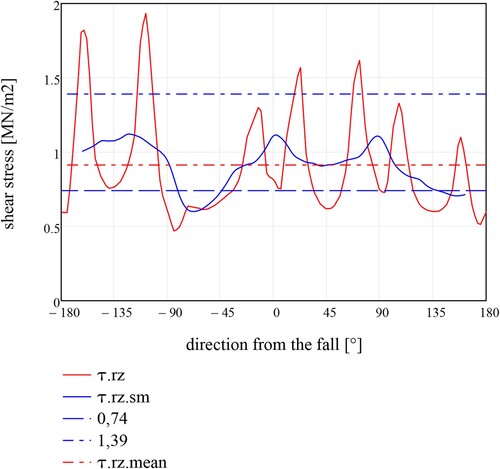
From the results, it is most probable that bending reinforcement reached yielding in some part of the base slab. After that, some part of the base slab had reached punching failure. At the same time, load was transferred more directly through the base pressure. That has been the smoothen a brittle nature of the punching failure. Based on the model, 38 MN was transferred through the shear punching control section.
The support reactions Z of the piles are shown in . The normal forces of the piles transferred a total of 58 MN of gravity loads. The support reactions, and normal forces of the piles, are highly redistributed from the results of the designed pile group geometry. The actual inclinations and poor support of pile 10 has a clear affect.
It can also be seen that the stiffness of the base slab has a clear outcome on the support reactions. The corner piles bear much less loads compared to the other piles. Further, the pile group with designed geometry leads to piles in tension, which have been without consideration if the pile forces have been designer with an assumption of the infitely stiff base slab. The original design has been conducted with this last assumption. As a worst case, this has been led to a double pile loads and that shear stresses are distributed very differently in the base slab.
A large part of the loads in steel shells are transferred through steel plate 5 in the connection of the bottom cylinder and the conical part of the tank. Roughly 80% of the vertical loads of the steel parts is transferred through plate 5. Hence, proper function of the welds is crucial. Based on the model, the highest vertical stress in the plate was 70 MPa before the collapse. This would mean that a-dimension should be roughly 10 mm based on the yield of the base material, if the connection would work perfectly without additional bending due to eccentricities.
It was brought up in Ref. [Citation5] that there have been additional stresses due to bending. The actual weld a-dimension was roughly 15 mm, with a minimum of 10 mm. Hence the material has been yielding on welded areas and the break has not been so far away. This also leads to the conclusion that the welds might have failed during use even had the foundation been stronger, because the loads would have been higher when the tank would have been filled up.
The results of the bottom cylinder showed also, that due to the deformations of the base slab, the stresses are redistributed, and the steel shell is arching the loads above the softer part of the foundation. This might have led to stress concentrations during the collapse, and that the welds might have failed already in an earlier stage.
Potential Failure Mechanisms
Based on the original forensic investigation and the supplementary study carried out here, the most probable sequence of the different failures can be inferred.
The translational displacement of the base slab and the resulting tilting of the tank initiated because of deficiencies of the piles. The inclinations of the piles deviated a lot from the designed ones. This led to a lateral resultant component being activated owing to the improper inclinations of the piles. The results from the analysis correspond with the observations before the collapse.
It is most probable that many of the piles were not on a firm rock surface. In particular, pile 10 was not working as designed. Piles 6 and 8 were driven after mining boulders. This most probably led to a situation where the modulus of the subgrade reactions was stiffer at that side of the base slab. The tip of the piles that were driven more loosely than others penetrated deeper. At the same time, more loads were transferred trough the stiffer piles which led higher settlements of the piles tips.
More deformations took place because of the deformations of the base slab. At the same time, more load was transferred with the base pressure of the base slab. The deformations of the slab led to a redistributing of stresses in the steel tank. When deformation of the base slab increased, probably even up to yielding of the bending reinforcement, the punching shear failure took place. This most probably started at the side of pile 10 because the bending moments were very high at that side. The results from analysis correspond well with the observed fracture lines after the collapse.
An increasing amount of gravity load transferred through the base pressure. When the tilting continued, the soil started to yield under the base slab. The rest of the load-bearing capacity of the base slab was still in place. This might have occurred even earlier when the 1 m of tilting was observed before the collapse. There are several options after the previous stages. When the tilting reached a magnitude of more than 1 m, some of the following took place first or simultaneously:
the conical steel cylinder buckled next to plate 5;
welds of the steel plate started to break owing to tension and bending of the detail;
at the base, the connection bars between the steel tank and the base slab started to break in tension.
Even had the slab and the piles been stronger, the welds of plate 5 might have broken later when the tank was completely filled. Without plate 5, the steel tank would have collapsed.Citation5
Conclusions
Many lessons were learnt after the collapse. A third-party review of designs became much more commonplace in construction in Finland after this incident. A stricter requirement mandating a competent design and construction team with sufficient resources was put in place.
Large-diameter steel pipe piles were a rather new product on the market when the tank was built. The piles were clearly too small for their purpose, and their driving was done with too small a machine and without proper geotechnical requirements for the piling work. After the collapse, pile driving analysis to verify bearing capacity has improved a lot. This method is currently very common in construction in Finland. The design methods of the piles have also been improved in order to avoid excessively small piles. It has been acknowledged that there should have been much more open discussion about new products and their characteristics.
The inclinations and lengths of the piles included many deficiencies. There was clearly a need, which has only been adopted later, for the structural system to be checked with actual inclinations and lengths of the piles, especially when tolerance limits were exceeded. However, pile forces are usually designed assuming an infinitely stiff base plate, or an elastic uncracked base plate. For example in this case, when cracked stiffness properties were assigned, the pile forces changed remarkably. Hence, there is a need to check pile forces against the cracked section properties of the base slab.
This study has revealed new aspects related to the original forensic investigation. The transitional displacement of the foundation was observed before the collapse. This had not been studied in depth earlier during the original forensic investigation. The cause was the pile group geometry realized in practice, which led to a lateral component of the pile axial forces. This leads to the conclusion that there is a clear need to have as open a discussion as possible between the parties involved, external experts and the scientific community in the case of a collapse. However, in general, legal implications often severely limit discussion. This is a challenge because lessons learnt are consequently not distributed well enough.
When discovering the main reasons for the collapse, the question “Would this collapse have taken place in any case without that deficiency?” helps to see each concern in relation to the others. Most probably, the greatest factor in this case has been the insufficient bending reinforcement of the base slab. However, there might even have been a collapse if there had been more reinforcement, because of deficiencies in the piles and in the weld of plate 5. The collapse showed that there were many technical reasons for the collapse, not only one. This is found to be the case in many collapses.Citation24,Citation25
Acknowledgements
The authors wish to thank the Finnish Safety Investigation Authority for providing information and documents regarding the collapse of the pulp tank in 1996.
Disclosure Statement
No potential conflict of interest was reported by the authors.
Data Availability Statement
The data and materials that support the results or analyses presented in this paper are freely available upon request. The original forensic investigation reports are available from the Safety Investigation Authority (Finland).
References
- Safety Investigation Authority (Finland). The steel tank downfall in Valkeakoski, 27 March 1996, Tutkintaselostus B 1/1996 Y; 1998. p. 81 + 3 app. p.
- VTT Technical Research Centre of Finland. SAP-Massatornin kaatumiseen liittyvän betonirakenteisen anturalaatan betoniterästen kunnon tutkiminen (Laboratory testing of rebars from samples of the base slab from SAP-Pulp tank). RTE30187/96. VTT Technical Research Centre of Finland; 1996. p. 3.
- Penttala V, Hassinen P. Lausunto UPM-Kymmene Tervasaaren massasäiliön kaatumiseen johtuneista syistä (Statement of reasons for collapse of UPM-Kymmene pulp tank); 1998. p. 21.
- Kukko H, et al. SAP-Massatornin kaatumiseen liittyvän betonirakenteisen anturalaatan tutkiminen (Study of reinforced base slab of collapsed SAP paper pulp tower), RTE30083/96. VTT Technical Research Centre of Finland; 1996. p. 21.
- Rahka K. UPM-Kymmene/Tervasaaren tehtaiden rakenteilla olleen SAP-massasäiliön kaatumiseen liittyvät säiliön teräsrakennetutkimukset (Study of steel tank of under construction collapsed SAP paper pulp tower), VAL72-7131. VTT Technical Research Centre of Finland; 1997. p. 16 + 17 app. p.
- Törnqvist J. SAP-Massatornin kaatumiseen liittyvä betonisen anturalaatan perustusten tutkiminen (Study of foundations of collapsed SAP paper pulp tower), 312/98. VTT Technical Research Centre of Finland; 1997. p. 29 + 16 app. p.
- Braestrup M. Pulp Tank Foundation Failure – Assessment of Punching Shear Capacity according to Plastic Analysis; 1997.p. 4.
- A-Insinöörit Oy. UPM Tervasaaren SAP-massasäiliön sortuman tutkintalautakunnalle (Response of structural designer to the investigation board).
- Engagement district attorney of Valkeakoski. 2000.
- YIT-Teollisuus. SAP-Massatorni V = 6000 m3. Structural drawing of bar connection between steel tank and foundation slab, No. 3669-2. p. 1.
- A-Insinöörit Oy. Dimensions and reinforcement drawing of base slab. 21-210 (02); 1995. p. 1.
- Lindberg R. UPM Kymmene, massasäiliön vaurioitumiseen liittyvät tekijät (Factors realted to collapsed paper pulp tank). Tampere University of Technology; 1996. p. 14.
- LUSAS. Modeller reference manual – LUSAS Version 19.1 Issue 1; 2021.p. 782 + 42 app. p.
- Marti P, Alvarez M, Kaufmann W, Sigrist V. Tension chord model for structural concrete. Struct Eng Int. 1998; 8(4): 287–298. doi:10.2749/101686698780488875.
- Eurocode 2: Design of concrete structures – Part 1-1: General rules and rules for buildings. CEN European Committee for Standardization; 2015.p. 194 + 24 app. p.
- Johansen KW. Brudlinieteorier, Gjellerup, Copenhagen 1943, English Edition. London: Yield Line Theory, Cement and Concrete Association; 1962. p. 181
- Rausch E. Maschinenfundamente und Andere Dynamisch Beanspruchte Baukonstruktionen [Machine foundations and other dynamically loaded structures], part 2. In: Taschenbuch für Beton-, Stahlbeton- und Spannbetonbau sowie die verwandten Fächer Beton-Kalender (eds). Berlin: Ernst & Sohn; 1973. p. 549–645.
- Finnish Traffic Agency. Teräsputkipaalut (Steel pipe piles). ISBN 951-726-617-0; 2000.p. 81 + 3 app.p.
- Finnish Traffic Agency. Liikuntasaumattoman sillan suunnittelu (Design of integral abutment bridges), Väyläviraston ohjeita 9/2021. p. 51 + 26 app.p.
- Fédération internationale du béton. Fib model code for concrete structures 2010. Germany: Ernst & Sohn; 2013. p. 434.
- Muttoni A. Punching shear strength of reinforced concrete slabs without transverse reinforcement. ACI Struct J. 2008; 105(2): 163–172.
- Muttoni A, Simoes JT, Faria DM, Ruiz MF. A mechanical approach for the punching shear provisions in the second generation of Eurocode 2. Hormigón y Acero. 2023. doi:10.33586/hya.2022.3091.
- Muttoni A, et al. Background document to Clause 8.4 Punching, Background Document for FprEN 1992-1-1, CEN/TC 250/SC 2 N2087, pp. 338–357.
- Matousek M, Schneider J. Untersuchungen zur Struktur des Sicherheitsproblems bei Bauwerken. Institut für Baustatik und Konstruktion Eidgenössische Technische Hochschule Zürich, Zürich 1976.
- Scheer J. Failed bridges: case studies, causes and consequences. Germany: Ernst & Sohn; 2010. p. 253. doi:10.1002/9783433600634.