
 ?Mathematical formulae have been encoded as MathML and are displayed in this HTML version using MathJax in order to improve their display. Uncheck the box to turn MathJax off. This feature requires Javascript. Click on a formula to zoom.
Abstract
This study is focused on the heterogeneous corrosion phenomenon of the general segment of suspension bridge main cables in mountainous/plain areas, specifically focusing on the uppermost surface. The primary objective of this research is to elucidate the corrosion mechanism by investigating the corrosion environment and performing corrosion acceleration tests using simulated ropes. Consequently, it has been revealed that during the summer season, the surface temperature of the rope reaches approximately 65°C, corresponding to the zenith of zinc corrosion rates. Moreover, in the upper surface of the rope, which is particularly susceptible to the influence of solar radiation, it has been disclosed that condensation occurs as a non-rainfall-related factor, creating an environment conducive to condensation. These factors suggest that the moisture supplied to the upper surface and the residue of corrosive elements exert an influence on the skewed corrosion mechanism of the rope surface.
Introduction
The cables utilized in cable-supported bridges, such as suspension and cable-stayed bridges, serve as vital support structures for the entire bridge, and thus, long-term durability is imperative. And there are primarily two types of cable for cable-supported bridges:
Parallel wire strand, which are bundled with hot-dip galvanized wire (hereinafter referred to as “wire”) in parallel to form a cable and are used in relatively long-span suspension bridges. The corrosion prevention method utilized for the large cables employed in such long-span suspension bridges requires specialized techniques, because the cable is composed of many wires in parallel. Then wrapping system using galvanized wire or rubber tape are applied to the exterior of the cables, furthermore dehumidification systems which blow dehumidified air into the cable's interior are developed and applied to the recent large suspension bridges to control humidity of the cable interior.
Wire ropes, which are composed of multiple strands/wires twisted together to form a structural rope (hereinafter referred to as “ropes”) and are utilized in relatively short/middle-span cable-supported bridges. In recent years, there have been instances of severe corrosion and cable/hanger rope fractures in such cable-supported bridges. These issues have resulted in catastrophic bridge failures, thereby highlighting the gravity of this issue.Citation1–7
As a maintenance and repair measure, cable dehumidification systems are installed to inhibit corrosion by eliminating water, which is a known cause of corrosion, in long-span suspension bridges.Citation3 However, such systems are not suitable for cables composed of single/multiple wire ropes for the cable-supported bridges, because small cable diameter and polygonal cable arrangement would cause technical and economic issues.
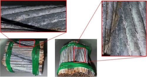
In the disassembly corrosion investigation of a suspension bridge main cable, it has been confirmed that severe corrosion occurs on the upper surface, and the center strands tend to be highly sound.Citation8 Additionally, in the corrosion investigation of the general part of the main cable of the Yunoki Bridge (completed in 1971, Kochi Prefecture, Japan) shown in a, the most severe corrosion occurs on the upper surface, and it has been confirmed that the center or lower ropes tend to be highly sound, even in cables consisting of multiple ropes. The corrosion occurrence on the upper and lower surfaces of the stay cables in Gasshou Bridge (completed in 1979 in Toyama Prefecture, Japan) differs, as shown in b. Despite being an arch bridge, Kagamigawa Bridge (completed in 1981 in Kochi Prefecture, Japan) has its arch rib and girder connected by hanger ropes. The bridge is in a densely populated area with heavy traffic in Kochi City and is situated near the coastline, making it a bridge that spans over a more challenging corrosion environment than the mountainous/plain area. Nonetheless, it can be seen from c that the corrosion condition on the upper and lower surfaces of the rope differs. This phenomenon is the same as Yunoki Bridge located in mountainous area.
Table 1: Corrosion investigation of bridge cables
Many cable-supported bridges utilized only hot-dip galvanized wire ropes without painting in mountainous/plain area in Japan since corrosion resistance of galvanizing is excellent. However, severe corrosion on cables is observed even in mountainous/plain area.
shows examples of the relationship between water temperature and corrosion rate of zinc, as well as the properties of corrosion products. The testing method as follow: A zinc specimen (99.9% purity) with dimensions of 8 × 12 × 0.076 cm is placed in distilled water saturated with air, and the corrosion rate is measured by adjusting to a specific temperature. The testing period is for 15 days. After the test, an examination and removal of corrosion products on the specimen surface are conducted, and the corrosion rate is calculated by measuring the weight loss. It is evident that the corrosion rate is high within a temperature range of 55–95°C, and corrosion is most severe around 65°C.Citation9–11 From the above, it is conjectured that the concentration of corrosion on the upper surface of the cable is probably accelerated by residual moisture on the cable surface, which is retained due to factors such as rainfall, and subsequently influenced by the high temperatures resulting from solar radiation.
Table 2: Example of relationship between zinc corrosion layer and water temperature
This study aims to clarify the corrosion mechanism of the general part of the suspension bridge main cables treated only with hot-dip galvanizing located in mountainous/plain areas far from the coast. Specifically, environmental corrosion investigation using a simulated rope and corrosion acceleration tests were conducted to determine whether there are accelerated corrosion factors on the upper surface of a cable or not.
This paper is structured as follows: Section 2 outlines the research methodology employed to investigate the various factors that promote corrosion on the upper surface of ropes in actual environment settings. The variables closely examined include temperature, humidity, rope surface temperature, and corrosion current, which are significantly linked to the corrosive environment. In Section 3, the accelerated corrosion test was conducted, considering the investigation results obtained from the corrosion environmental investigation discussed in Section 2. This test enabled the comparison of the corrosion state, with emphasis on the relationship between surface temperature, air temperature, humidity, and corrosion current. Section 4 provides a comprehensive summary of the key findings derived from this study.
Corrosion Environmental Investigation
Specimens
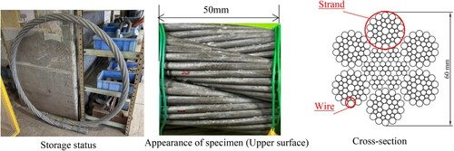
In this study, a structural strand rope with a nominal rope diameter of Φ60 mm was used as the specimen. This is the diameter typically used for the main cables of short/middle-span suspension bridges located in mountainous/plain areas. The rope structure is defined as a bundle of individual galvanized steel wires that are combined into strands, which are then bundled or twisted together in parallel to form a rope or cable structure. This rope is the same as the hanger rope used in the Ohnaruto Bridge.Citation12 It is hot-dip galvanized with 260 g/m2 (equivalent to a galvanizing thickness of approximately 40 µm) on the surface of the steel wires. The rope has been stored indoors at the Tokyo Rope Mfg. Co., Ltd. Tsuchiura factory since its manufacture in 2008, and no corrosion has been observed on the zinc coating surface. However, over time, the shine of the zinc coating on the surface has disappeared. The length of the tested specimen was set at 50 mm. shows the appearance and cross-section of the specimen used in this study.
Fig. 1: Appearance and cross-sectional view of the specimen
Investigation Methods
In this section, whether there are many factors that promote corrosion on the upper surface of the rope in the actual environment was investigated by outdoor exposure monitoring.
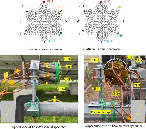
Specifically, the temperature, humidity, rope surface temperature, and corrosion current, which are closely interrelated with the corrosion environment were measured. The location was meticulously selected near the Gifu University disaster prevention engineering laboratory, with the intention of avoiding shading effects by few tall buildings in the vicinity. The specimens were deliberately installed at a height of approximately 1.5 m from the ground to evaluate and compare the installation directions, with the longitudinal directions facing east–west and north–south, respectively.
| (a) | Measurement method of surface temperature | ||||
The methodology utilized to gauge surface temperature entailed installing thermocouples at six locations in total. These comprised one on the upper surface of the rope (or strictly speaking, the wire surface), four on the sides, and one on the lower. This was performed to ascertain whether there were discernible temperature variations between areas that were exposed to sunlight and those that were not. Moreover, temperature and humidity were gauged by placing a thermometer and hygrometer in the vicinity of the specimen. The surface temperature measurement locations are shown in . The installation of thermocouples was achieved by polyimide tape that exhibited excellent insulation and heat resistance. Additionally, to account for any thermal influence arising from the installation fixture to the specimen, polyimide tape was applied to the end of the specimen.
| (b) | Measurement method of corrosion occurrence | ||||
Fig. 2: Surface temperature measurement points
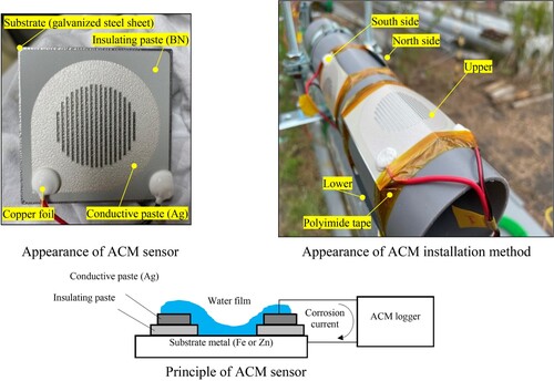
The technique employed to determine the occurrence of corrosion involved the use of Atmospheric Corrosion Monitor sensors (ACM sensor, manufactured by Syrinx Co., Japan). shows the appearance, principle, and installation method of the ACM sensor. The ACM sensors possess the capability to measure the electrochemically generated corrosion current of metals due to environmental factors directly. By analyzing the output obtained from the ACM sensors, the degree of corrosiveness in the environment, including occurrence of corrosion and corrosion rate, can be assessed quantitatively and directly. The underlying principle behind this technique involves the use of sensors composed of a substrate of target metal (steel substrate; Fe or zinc-plated steel substrate; Zn) onto which a laminated and hardened insulation paste (BN; boron nitride) and a conductive paste (Ag; silver) have been printed, with the insulation maintained between the paste and the substrate. When exposed to the atmosphere, a thin film of water forms between the two metals due to rain and condensation, causing galvanic current to flow. As the value of this current is highly correlated with the corrosion rate, it becomes feasible to monitor the corrosion in the atmospheric environment.Citation13 The plate-shaped ACM sensor used in this study is designed to detect corrosion across the entire sensor area. It is important to note that it cannot capture localized corrosion, such as corrosion at the contact points between strands or between wires.
Fig. 3: Appearance, principle, and installation method of the ACM sensor
In this study, four sensors, including one on the upper surface, one on the lower surface, and two on the side surfaces, were attached to the rope-shaped simulated specimen, which was set up in the east–west axis direction. The substrate with 3 mm thickness of ACM sensor was zinc-plated to match the condition of the galvanized wires and was bent to match the shape of rope curvature. The sensor end was fastened with polyimide tape. The measurement period for temperature, humidity, surface temperature of the rope, and corrosion current was set as a 30-day period from September 8, 2021, to October 8, 2021, with the highest temperature being 25°C or above on summer days. The measurement interval for temperature, humidity, and surface temperature of the rope was once every minute, while that for corrosion current was once every 20 s. In conventional exposure tests, investigations are typically conducted over a minimum period of one year. It is important to note, however, the examination was conducted in summer season when the corrosion impact is higher.
Investigation Results
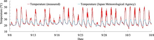
First, shows a comparison between the temperature measurements obtained from the actual data and the data provided by the Meteorological Agency.Citation14 During the measurement period of this study, the highest and lowest temperatures recorded by the Meteorological Agency were 31°C and 18°C, respectively. In contrast, the actual measurements revealed the highest and lowest temperatures of 52°C and 15°C, respectively. The Meteorological Agency employs an electric thermometer to measure temperature, which is situated at a height of 1.5 meters above the grass surface in a location with good ventilation and sunlight. Additionally, the electric thermometer is kept in an air duct to avoid direct sunlight exposure. Hence, the difference in temperature measurements is attributed to the differences in measurement methods. This study refers to the actual data that is exposed to direct sunlight.Citation15
Fig. 4: Temperature comparison between actual measurements and Meteorological Agency data
Second, shows the measurement results of the surface temperature of the specimen in the East–West direction (CH1 to CH6) during a specific measurement period from October 3-6. The surface temperature of the rope was observed to range between 24°C and 69°C. Thus, it was established that the surface temperature of the rope reaches the highest corrosion rate of the zinc plating around 65°C.
Fig. 5: Surface temperature of the specimen in the East-West direction (CH1 to CH6)
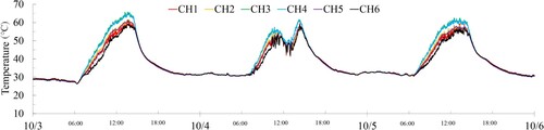
Within the temperature range of approximately 30°C, there was almost no temperature difference detected at each measurement point. Within the temperature range of approximately 60°C, it was verified that the surface temperature of the specimens in the east–west axis direction was higher in the order of CH3, 4, 2, 5, 1, and 6. The surface temperature of the specimens in the north–south axis direction also exhibited a similar trend, with higher temperature in the order of CH9, 10, 8, 11, 7, and 12. In other words, it is assumed that there exists a gradient from the lower right side to the upper left side.
However, this study necessitates further investigation and examination due to (1) the fact that each survey location represents only one section, (2) the difference in temperature between the highest and lowest temperatures is not significant, with a maximum difference of 7°C, (3) the specimens are of limited length, and there is a possibility that they are influenced by the thermal energy reflected by the specimen installation fixtures, installation locations, single-tube pipes, and sunlight reflected from the ground, (4) the distinction between the actual bridge cables and the specimens, as the actual bridge cables are situated at a higher location with less influence from the reflected sunlight from the ground.
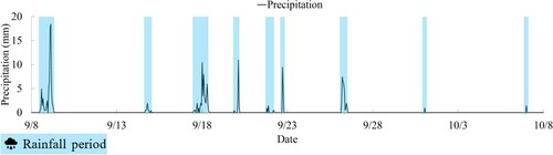
The results of surface temperature, air temperature, humidity measurements, and the dew point temperature calculated from these measurements, are shown in . shows the corrosion current measurement results. The surface temperature represents the average of CH1 to CH6. Additionally, shows the amount of precipitation in Gifu City during the same period, as measured by the Meteorological Agency. The precipitation amount is indicated by the light blue range to represent the periods of rainfall. The dew point temperature refers to the temperature at which gas condenses as it is cooled, and the greater the humidity, the greater the amount of water vapor. When a substance with a temperature lower than its saturation temperature encounters this gas, condensation occurs. The dew point temperature is calculated using Magnus’ formula (1),Citation16–18 which involves measuring air temperature and humidity.
(1)
(1) where the parameter td is the dew point temperature (°C), t is the air temperature (°C), and RH is the relative humidity (%). Additionally, Magnus’ formula was assessed by Alduchov et al. based on the most recent vapor pressure measurements, and the coefficients A1 = 17.625 and B1 = 243.04°C were suggested. These coefficients have been recognized to provide exceedingly precise values for the computation of the dew point temperature from air temperature and humidity, and thus were utilized in this study as above.
Fig. 6: Results of surface temperature, air temperature, humidity, and dew point temperature
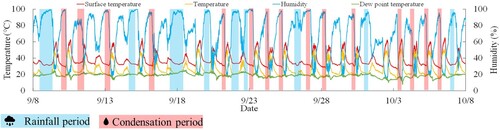
Fig. 7: Measurement results of corrosion occurrence
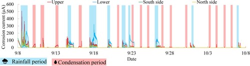
Fig. 8: Gifu city precipitation for the same period according to the Japan Meteorological Agency
From , it can be confirmed that during sunset, when the surface temperature of the specimen was approximately 35°C, the humidity level was measured to be 90% or higher, indicating a state of high humidity. Conversely, during the daytime period, when the surface temperature of the specimen was around 65°C, the humidity tended to decline to approximately 20%. Consequently, it can be said that during the measurement period in summer, the environment was defined by recurrent episodes of high temperature and high humidity.
Based on , it was observed that the corrosion current of the ACM sensor demonstrated sensitivity during the rainy period, implying that the existence of moisture, a corrosion-inducing factor, expedited corrosion. It has been reported that during rainfall, a corrosion current output value of 200μA or more can be obtained for the ACM sensor (galvanized steel substrate).Citation19 Additionally, the corrosion current values of the upper and lower surfaces were found to be greater than those of the two lateral surfaces. Due to rainfall, it can be said that moisture tends to linger on both the upper and lower surfaces. On the other hand, the ACM sensor has a flat shape, and there is a possibility that moisture may be retained on the surface of ropes with complex unevenness. Furthermore, due to the irregularities on the rope surface caused by wires and the difference in specific heat between the ACM sensor and the rope, the wetting duration on the rope surface may be longer than the corrosion current obtained from the ACM sensor. This extended wetting period could expose the rope surface to sunlight without moisture evaporation.
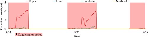
Additionally, it has been verified that the period during which the rate of corrosion is evaluated is not limited to the rainy season, but also extends to other areas beyond it (shown by the pink region) as shown in . This corresponds to areas where the temperature decreases to the dew point temperature. Consequently, it is suspected that the temperature drop in this region reaches the dew point temperature, leading to condensation on the surface of the testing sample.
To verify the occurrence of condensation, an inquiry was conducted based on the relationship between temperature and humidity measured during the condensation period. The investigation employed a device that maintains constant temperature and humidity conditions, with the test environment being set to the temperature-humidity relationship measured during the condensation period shown in . The presence of condensation on the surface of the specimen was visually confirmed. The temperature-humidity cycle test parameters were set as follows: #1 temperature of 50°C, humidity of 25% for one hour, and #2 temperature of 20°C, humidity of 95% for one hour.
The results of the investigation into the occurrence of condensation on the surface of the specimen are shown in . Visual observation confirmed that condensation occurred on the entire wire surface. These observations were made during the transition period from cycle #1 to #2. When calculating the water vapor amount, it is found that at a temperature of 50°C and humidity of 25%, there is 20.72 g/m3 of water vapor, whereas at a temperature of 20°C and humidity of 95%, there is 16.44 g/m3 of water vapor. In other words, cooling from 50°C and 25% humidity to 20°C and 95% humidity results in a net difference of 4.28 g/m3 of water vapor, leading to condensation. The vapor amount was calculated using Eq. (2).Citation20
(2)
(2) where at is the amount of saturated water vapor (g/m3), and t is temperature (°C).
Fig. 9: Investigation results of dew condensation on the surface of the rope specimen
Therefore, it became evident that condensation occurs in the pink-shaded region in . The condensation period is primarily observed during the early morning, from around 5 am to 8 am Additionally, it is noteworthy from the enlarged view in of that the condensation period is primarily associated with a significant increase in the corrosion current on the upper surface, which is considered to be caused by condensation accumulation on the upper surface of the rope.
Fig. 10: Measurement results of corrosion occurrence (Period: From 24th to 26th September)
On the other hand, ACM sensors designed to measure condensation are thought to have fewer irregularities and a smaller specific heat capacity than the surfaces of the rope. In other words, moisture may dry out more quickly with ACM sensors. However, due to the increased irregularities and larger specific heat capacity of rope surfaces compared to ACM sensors, it is suggested that the surfaces of the rope are more likely to retain moisture from rain or condensation. Specifically, in the actual environmental conditions of the cable, moisture is heated during the late morning around 11 am to early afternoon around 2 pm, when surface temperatures are at their highest. The aforementioned period corresponds to a high-temperature, low-humidity range of 50–65°C and 20–30% humidity. However, it is estimated that corrosion is likely to be accelerated even in low humidity if moisture is retained on the upper surface of the rope or between the wires.
Accelerated Corrosion Test
Specimens
This section outlines the results of the investigation into corrosive environments in the preceding chapter. Accelerated corrosion tests were conducted, taking into consideration the relationship between surface temperature, air temperature, and humidity, and comparing the corrosion status. The same specimen used in the corrosion environmental investigation was used, with a specimen length of 100 mm.
Test Method
The details of the accelerated corrosion test method are described below. shows a list of test conditions for each test case. The specimens were compared in two different corrosive environments.
Table 3: Conditions of each test case
The two different corrosive environments were as follows: Case-1, a corrosive environment with a temperature of 35°C and humidity of 100%; and Case-2, a corrosive environment with a temperature of 65°C and humidity of 100%. The test conditions were determined based on the relationship between surface temperature, air temperature, and humidity observed in in the previous chapter.
Case-1 focuses on a period of approximately 35°C, which is the lowest surface temperature value. During this period, the humidity was over 90%, resulting in a high-humidity environment. The test machine used was a DKM400 manufactured by Yamato Chemical Co., Ltd., and a humidifier (always humidified) was employed.
Case-2 focuses on the period with the maximum surface temperature, approximately 65°C. During this period, the humidity is low, around 20%. However, considering the potential for water accumulation on the rope surface due to rainfall or condensation, the temperature was set consistently at 65°C, and the humidity was set at 100%, as discussed in the preceding section. The testing machine used was the Espec PL-3KP.
The accelerated corrosion promotion period was 88 days (2112 h). In this study, all specimens were installed horizontally, as assumed for the central part of the main cable of a short/middle span suspension bridge constructed in a mountainous/plain area away from the coast.
Test Results
The visual investigation results are shown in . In Case-1, the entire surface and interwire shown white rust, albeit with relatively mild corrosion. In Case-2, after white rust appeared on the entire surface and between wires, red rust manifested itself over a wide area. For both cases, as the experiments were conducted under constant temperature and humidity conditions throughout, no significant differences were observed in the corrosion status of the upper, lower, and side surfaces.
Table 4: Appearance after the test of 2 cases (Upper surface)
A comparison between Case-1 and Case-2 reveals that Case-2, under high-temperature and high-humidity conditions, experiences a corrosion situation, with sufficient corrosiveness even in the absence of water stagnation caused by the adhesion and accumulation of chlorides as observed in salt spray test. Case-1 represents conditions that may occur during the evening to early morning in the summer season. Case 2 is unlikely to occur in actual corrosion environments, but there is a possibility of its occurrence under specific conditions. This refers to situations where moisture is retained on the surface of the rope, especially on the upper side, or between the wires.
Conclusions
The findings from this study are summarized below:
During the measurement period in summer, characterized by repeated episodes of high temperature and high humidity, this investigation revealed that the highest temperature on the surface of the rope reached around 65°C, which corresponds to the maximum corrosion rate of zinc.
The investigation has revealed that condensation, in addition to rainfall, is one of the primary causes of corrosion. This is facilitated by the influence of sunlight, which causes the rope surface to heat up during the day and cool down at night, creating temperature and humidity differences that are conducive to condensation. These temperature and humidity fluctuations are more likely to occur on the upper side of the rope, which is more susceptible to the effects of sunlight, suggesting a higher likelihood of condensation on the upper surface of the rope. However, it is noted that this study is limited to the summer season, and based on the measurements of corrosion currents, it is evident that rainfall has a more pronounced effect on corrosion acceleration compared to condensation.
Corrosion progresses gradually in an environment with a temperature of 35°C and 100% humidity, whereas in an environment with a temperature of 65°C and 100% humidity, corrosion advances at a faster rate. The former represents conditions that may occur during the evening to early morning in the summer season. The latter, though less likely in actual corrosion environments, is that could occur under specific conditions. This involves the retention of moisture on the surface (Especially, the upper surface) of the rope or between the wires.
In other words, due to the surface irregularities caused by the wires on the rope, the retention of moisture on the upper surface of the rope. Then, when the surface temperature reaches the high-temperature range may accelerate corrosion. Repeating this process could result in uneven corrosion of the upper strands located on the outer surface of a cable composed of multiple ropes, leading to a tendency for corrosion to concentrate on the upper surface of the cable. This implies that relying solely on zinc coating for primary corrosion protection may be inadequate, even in mountainous/plain environments.
The investigations and experimental results presented in this study ultimately provided important recommendations for the maintenance and management of suspension bridges.
Disclosure Statement
No potential conflict of interest was reported by the author(s).
Data Availability Statement
The data supporting the results of this study are available from the corresponding author upon reasonable request.
Correction Statement
This article was originally published with errors, which have now been corrected in the online version. Please see Correction (http://dx.doi.org/10.1080/10168664.2024.2331379).
Additional information
Funding
References
- Stahl FL, Gagnon CP. Cable corrosion. New York: ASCE Press, 1996.
- Betti R, Yanev B. Conditions of suspension bridge cables: New York City case study. Transp Res Rec: J Transp Res Board. 1999; 1654: 105–112.
- Furuya K, Kitagawa M, Nakamura S, Suzumura K. Corrosion mechanism and protection methods for suspension bridge cables. Struct Eng Int. 2000; 10(3): 189–193.
- Kameyama S, Hiramatsu T. Reinforcement work and long-term monitoring of steel suspension bridges due to partial breakage of main cables, 18th Civil Engineering Construction Management Technology Papers; 2013. p. 111–114,
- Colford BR. Forth road bridge – maintenance and remedial works, proceedings of the institution of civil engineers. Bridg Eng. 2008; 161: 125–132.
- Betti R, Khazem D, Carlos M, Gostautas R, Virmani YP. Corrosion monitoring research for city of New York bridges. Publication. FHWA-HRT-14-023; 2014.
- Nakamura S, Miyachi K. Ultimate strength and chain-reaction failure of hangers in tied-arch bridges. Struct Eng Int. 2021; 31: 136–146.
- Kinoshita K, Yano Y, Hatasa Y, Hasuike R, Miyachi K. Examination of corrosion evaluation criteria based on rust composition analysis in corrosion investigation of actual suspension bridge main cables, 2020; 66A: 431–442.
- Cox GL. Effect of temperature on the corrosion of zinc. Ind Eng Chem. 1931; 23(8): 902–904.
- Handbook of Metal Surface Treatment Technology, Metal Surface Technology Association. Nikkan Kogyo Shimbunsha. 1955; 583.
- Corrosion resistance data collection of hot-dip galvanized steel under various corrosive environments “Corrosion resistance of hot-dip galvanized steel sheets”. Nippon Steel Corporation. 2019: 1–25.
- Kitagawa T, Nagao Y. A study on repairing methods for hanger ropes of Ohnaruto Bridge. Honshi Tech Rep. 2006; 30(107): 15–21.
- Shinohara T, Motoda S, Oshikawa W. Evaluation of corrosivity in atmospheric environment by ACM (Atmospheric Corrosion Monitor) type corrosion sensor. Proceedings of the Prism 5: The Fifth Pacific Rim International Conference on Advanced Materials and Processing; Vol. 475–479; 2004. p. 61–64.
- Climate of Japan, Japan Meteorological Agency [cited 2022 Feb 2]. Available from: https://www.data.jma.go.jp/obd/stats/data/en/index.html.
- Observation equipment, Japan Meteorological Agency [cited 2022 Feb 2]. Available from: https://www.jma.go.jp/jma/en/Activities/surf/surf.html.
- Magnus G. Versuche über die Spannkräfte des Wasserdampfs. Ann Phys. 1844; 137: 225–247.
- Alduchov OA, Eskridge RE. Improved Magnus form approximation of saturation vapor pressure. J Appl Meteorol. 1996; 35: 601–609.
- Lawrence MG. The relationship between relative humidity and the dewpoint temperature in moist air. Am Meteorol Soc. 2005; 86: 225–233.
- Ito Y, Kainuma S, Oshikawa W. Study on evaluation of atmospheric corrosion environment of steel members using ACM type corrosion sensor of Zn/Ag pair. Proceedings of the 66th Annual Conference of the Japan Society of Civil Engineers; 2011. p. 1165–1166.
- Tomitaka S. On the calculations of dew point from water vapor pressure. Tenki. 1988; 35(2): 115–126.