1. Introduction
Cycling science has undergone a great revolution in recent years. During individual time-trials, racing events in which cyclists race against the clock are not permitted to ride behind other cyclists where they gain advantage by drafting, understanding aerodynamics and the forces acting on the bicycle can lead to substantial gains in performance and lead to victory. In time-trial competition, the cyclist’s position on the bike has been widely studied and an optimized position reduces wind resistance and improves performance (Grappe Citation2009, Blocken et al. Citation2013). The cyclist’s position alone represents about 65–80% of the total aerodynamic drag. One means of optimizing performance is to modify the shape of helmets used in time-trials (referred to as ‘aero helmets’).
An alternative approach to investigating aerodynamics in sports sciences is the numerical one. Indeed, in recent years, Computational Fluid Dynamics (CFD) has been used and shown to be a powerful and efficient tool for simulating complex fluid flows. Defraeye et al. (Citation2010) evaluated the aerodynamic performance of different cyclist positions by means of CFD simulations and wind tunnel measurements. Sims and Jenkins (Citation2011) used the CFD method to improve aerodynamic design of the bicycle helmet.
The aim of the present study is to gain greater insight into the aerodynamics of time-trial helmets in real-world conditions using CFD. Three time-trial helmets of different brands and shapes have been considered. In order to reflect accurately real racing conditions, the following head positions have been tested:
| • | Head-up position (horizontal gaze) | ||||
| • | Head-down position (vertical gaze) | ||||
Simulations were performed for a velocity of 15 m/s corresponding to the average velocity during a flat route time-trial competition for an international class cyclist.
2. Methods
2.1. Geometry and computational grid
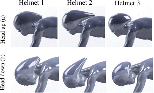
The resolution of a computational fluid dynamics problem requires several steps: the first being to define the geometry and the computational domain. For this, the numerical model of the cyclist’s body was obtained by scanning a world-class cyclist sitting on a bicycle in time-trial position without helmet on. Secondly, the three time-trial helmets were scanned using a 3D scanner (ARTEC®). Lastly, the helmets were fitted to the cyclist’s head, using CAD software (Figure ).
Figure 1. Defining the geometry of the test subject. For each time trial helmet: Head-up position (a), head-down position (b).

The three-dimensional grid was generated using the ANSYS Workbench Meshing® software and consists of a non-structured mesh composed of approximately 1.6 × 10⁶ tetrahedral and hexahedral elements.
2.2. Boundary conditions
A uniform constant horizontal velocity (15 m/s) was imposed at the inlet of the fluid domain (Figure ). At the outlet, a pressure outlet condition with ambient static pressure was imposed. A symmetry condition was imposed on the upper and side surfaces of the fluid domain. On the surface of the cyclist model, the no-slip wall boundary condition was considered.
2.3. CFD simulations
Simulations were performed using ANSYS Fluent 17.2© CFD code. The standard k–ε model was chosen to solve the 3D steady Reynolds averaged Navier-Stokes equations. During computations, convergence was monitored and was obtained when residuals displayed values less than 10−5.
3. Results and discussion
3.1. Modeling validation
The numerical procedure was validated by comparison with experimental and numerical data from Blocken et al. Citation2013. Our results are in good agreement with Blocken et al.’s findings obtained for a cyclist without bicycle setup in time-trial position.
3.2. Drag force
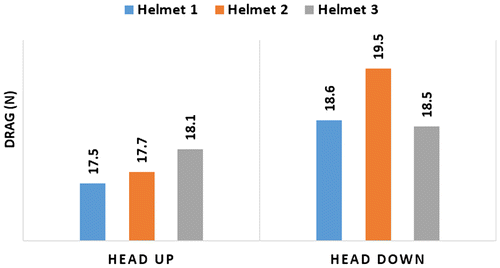
The drag force (FD, N) values for each helmet and both head positions are summarized in Figure . We have found that for the head-up position, the range of FD obtained was between 17.5 N (helmet 1) and 18.1 N (helmet 3), leading to a negligible difference of 0.6 N.
The difference between the three helmets is greater for the head-down position with a FD value ranging from 18.5 N (helmet 3) to 19.5 N (helmet 2). In head down position, minor differences were found between helmets 1 and 3 whereas helmet 2 provided the highest drag. Although the differences are small, we found that helmet 3 is the one whose drag is the lowest for the head-down position.
Helmet 1 offers an optimal trade-off with the lowest drag in the head-up position and a drag equivalent to that of helmet 3 in the head-down position. However, these findings were deduced from calculations performed with a specific and super-low head position and the results should be examined in that context.
4. Conclusions
The primary goal of this study was to evaluate the aerodynamic drag of three different helmets by quantifying both the influence of external geometry and head position.
In the head-up position, the three helmets present nearly equal performance. However, significant differences were deducted depending on the head position. In the head-down position, Helmets 1 and 3 exhibits the best aerodynamic performance. Due to its circular shape, helmet 3 offers similar performances whatever the head’s position.
Overall, given the small differences in drag forces in head-up position among the three helmets, and relatively greater differences in drag forces in the head-down position among the three helmets, helmet 1 offers the greatest advantage.
References
- Blocken B, Defraeye T, Koninckx E, Carmeliet J, Hespel P. 2013. CFD simulations of the aerodynamic drag of two drafting cyclists. Comput Fluids. 71:435–445.10.1016/j.compfluid.2012.11.012
- Defraeye T, Blocken B, Koninckx E, Hespel P, Carmeliet J. 2010. Aerodynamic study of different cyclist positions: CFD analysis and full-scale wind-tunnel tests. J Biomech. 43:1262–1268.10.1016/j.jbiomech.2010.01.025
- Grappe F. 2009. Cyclisme et optimisation de la performance : sciences et méthodologie de l’entraînement. 2ème éd. De Boeck.
- Sims BW, Jenkins PE. 2011. Aerodynamic bicycle helmet design using a truncated airfoil with trailing edge modifications. ASME 2011 International Mechanical Engineering Congress and Exposition, Vol. 6: Fluids and Thermal Systems; Advances for Process Industries, Parts A and B: 453–462.


