 ?Mathematical formulae have been encoded as MathML and are displayed in this HTML version using MathJax in order to improve their display. Uncheck the box to turn MathJax off. This feature requires Javascript. Click on a formula to zoom.
1. Introduction
Competitive swimming aims to achieve high performances by the only mechanical action of the swimmer in the fluid at rest. The cyclic action of the arms and legs generates a flow which, by the principle of reciprocal actions (Newton’s 3rd law) acts on the body surfaces. In this context, the hand movement is crucial. The hand propulsive forces directly depend on this flow. Study of these propulsive forces have made mostly from quasi-steady approaches (Schleihauf Citation1979), and results are commonly given in the form of lift (CL) and drag (CD) coefficients:
(1)
(1)
Where drag force (D) is defined as the force acting parallel to the flow direction, and lift forces (L) is defined as the force acting perpendicularly to the drag force. However, the quasi-static approaches are not sufficiently accurate because the flow has a complex vortex dynamics, unsteady and turbulent. Thus more and more unsteady analyzes are carried out, relying on several unsteady effects. In this context, this paper attempts to quantify the time-dependence of aerodynamic forces for a simple yet important motion. For this purpose, a CFD analysis was carried out in order to simulate the flow around a hand in translation at a constant velocity, from an impulsive start.
2. Methods
The flow was simulated using a URANS method (Samson et al. 2015). Equations were closed by the k-ω SST model, a moving mesh was used, in free surface condition. The movement consisted in translating a hand-forearm model at a constant velocity (2 m.s−1), from rest and for 1 second (we only analyze the data of the hand in this study, Figure (a)). This speed is close to the average velocities of the hand stroke swimming. The angle of attack varied from 0° (with the little finger as leading edge) to 180° (thumb), 21 simulations were computed (maximal step: 10°). Lift and drag force coefficients (CL(t) and CD(t) respectively) were then calculated using unsteady approach with L(t) and D(t) which are time-dependent:
(2)
(2)
where ρ is the fluid density, U is the velocity of the fluid relative to the hand, S is the maximum projected area of the hand. To assess the role of unsteady effects, drag and lift coefficients were calculated at different times of the flow: close to the start (at t = 0.1 s, characterizing an unsteady flow) and later (at t = 1 s, characterizing a quasi-steady flow). In order to correlate the force coefficients with fluid movement during translation of the hand, the flow was analyzed from the vorticity on a plane localized to the metacarpals at 0.75 m depth of the free surface.
3. Results and discussion
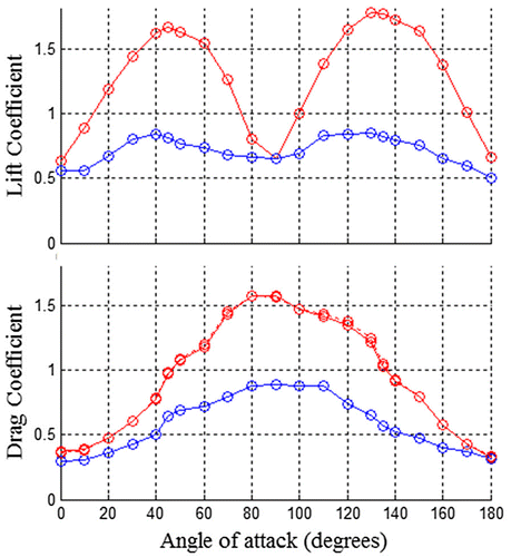
CL(t) and CD(t) plotted as functions of angles of attack are shown in Figure for 21 angles of attack between 0° and 180° (Reynolds number is close to 105).
Figure 1. Evolution of L and D coefficients with the angle of attack, at 2 instants of the path: t = 0.1 s, circle points, and t = 1 s triangle points against of angle of attack.

Figure shows that at low angles of attack (close to 0° or 180°), both force coefficients are close at t = 0.1 s and 1 s. When angle of attack increases, CL(t) and CD(t) coefficients obtained after 0.1 s are higher than those obtained after 1 s of flow. When angles of attack are between 10° and 170°, the lift coefficients were up to 100% higher at t = 0.1 s, compared to the values calculated after a displacement of 1 s. From 20° until 160°, the drag coefficient were up to 80% higher at t = 0.1 s, compared to the values calculated after a displacement of 1 s.
At t = 0.1 s, CL presented a maximum at 45° and even more at 130° when the leading edge is the thum. The highest CD is obtained for an angle of attack of 80°.
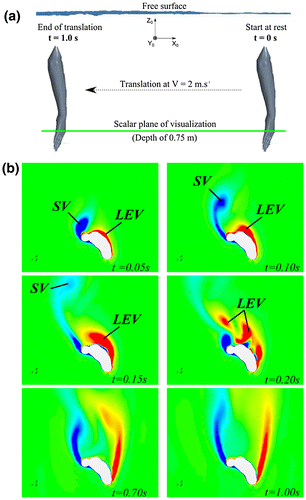
The time history of the hydrodynamic force coefficients is correlated with the pattern of vortex shedding by the hand. Indeed, in the Figure (b), when the hand movement begins we see the formation of a Starting Vortex (SV) on the trailing edge (in blue, at t = 0.05 s, on the top of the thumb). At the same time, a vortex rapidly develops on the leading edge (LEV) on the upper surface of the hand (in red, t = 0.05 s). Then, very quickly, the SV grows and is shedded in the wake (t = 0.15 s). The LEV grows, reaches a maximum at t = 0.15 s, then is separated in two structures and shedded in the wake (at t = 0.2 s). There is an important correlation between the formation of the LEV and the values of the coefficients: at t = 0.1 s the coefficients are almost twice as large as t = 1 s for the high angles of attack (close to 45° and 135°).
Figure 2. (a) Representation of the displacement of the hand-forearm segment; (b) Visualization of the vorticity (at 0.75 m of depth) of the fluid around the hand at different times of the path; SV: Starting Vortex; LEV: Leading Edge Vortex, for an angle of attack of 45°.

According to Dickinson (Citation1996), in quasi-steady flow, above a critical angle of attack (close to 15°), the flow separates off the trailing edge increasing pressure drag and attenuating circulatory lift which results a stall.
However, in unsteady flow, this phenomenon of stall is often delayed. This phenomenon, called delayed stall is due to the fact that when the flow separates from the leading edge of a biofoil it temporarily attaches to the upper surface in front of the trailing edge to form a leading edge bubble surrounding a vortice. This bubble (the LEV here) which is strongly attached, causes a rapid increase in forces by creating a depression on the upper surface of the biofoil. Thus, the presence of this LEV on the top of the hand transiently produce much larger circulatory forces than are possible in the steady state.
Even if the conditions of this study are not the same as the movement of a swimmer’s arms (extremely complex since in three-dimensional with large variations of linear and angular velocities), it makes it possible to highlight the role of delayed stall. Delayed stall may then be one of the unsteady effects which explains the sinusoidal paths of the arms in a short distance (notably in front crawl and backstroke) with large angles of attack making it possible to benefit of the attachment of the LEV over short durations. Besides, insweep and upsweep phases often have durations close to 0.2 s.
4. Conclusions
This study has highlighted the role of the delayed stall effect in the generation of unsteady swimming forces. These force coefficients are almost twice higher to those obtained in quasi-steady configurations. The LEV benefits both the drag and lift components, at a different angles of attack. Although the motion of this simulation is simple, it does serve as reasonable analysis model of certain aspects of the complex actual motion in swimming.
References
- Dickinson EW. 1996. Unsteady mechanisms of force generation in aquatic and aerial locomotion. Am Zool. 36:537–554.10.1093/icb/36.6.537
- Samson M, Monnet T, Bernard A, Lacouture P, David L. 2017. Unsteady computational fluid dynamics in front crawl swimming. Comput Methods Biomech Biomed Eng. 20(7):783–793.10.1080/10255842.2017.1302434
- Schleihauf R. 1979. A hydrodynamic analysis of swimming propulsion. Swimming. III:70–109.
