
Abstract
Fretting and corrosion at the taper-head interface in total hip arthroplasty has been reported as a potential cause of early failure of the implant system. The finite element (FE) method can be used to study the mechanics at the taper junction that are difficult to assess experimentally. Taper mismatch is one of the factors that can influence the performance of the taper junction. In this study we have assessed the effect of taper mismatch, in combination with assembly force on the volumetric wear. The study showed that higher assembly forces and smaller mismatches result in the least volumetric wear.
Introduction
Modular total hip replacements have been developed in the past to improve intra-operative flexibility, and to facilitate restoration of patient anatomy (Hozack et al. Citation1996; Srinivasan et al. Citation2012). Modular interfaces within femoral hip implant systems can take the form of modular necks, modular stem extensions, proximal bodies or the interface with the femoral head, but also includes taper adaptors for use with large diameter femoral heads or ceramic femoral heads. The modular tapers are generally conically shaped and can vary in size and material (Nassif et al. Citation2013; Mueller et al. Citation2017). The focus of this work was on the modular connection between a femoral stem and a taper adaptor intended for use with large diameter femoral heads.
Although there are many advantages of using modular junctions (Srinivasan et al. Citation2012), under certain circumstances they may be associated with additional risks, as described in reports on fretting wear at these locations (Goldberg et al. Citation2002; Higgs et al. Citation2013). Fretting wear is caused by small cyclic motions between two contacting surfaces, and is a result of a combination of mechanical and chemical processes, such as abrasion and corrosion. Fretting produces particles and metal ions that are released into the joint cavity, and can in some cases even lead to early failure of hip replacement (Delaunay et al. Citation2010; Swann et al. Citation2015).
One of the factors that may influence taper fretting and wear is the angular mismatch between the taper of the stem and the femoral head. A mismatch between the head and the stem is often designed into systems to ensure consistent performance, while a specified tolerance band is allowed in order to ensure manufacturability. The magnitude of the actual mismatch depends on the specific processes and tolerances prescribed by the manufacturer. A mismatch can result in the head seating at either the proximal or distal end of the stem taper, known as ‘tip fit’ and ‘base fit’, respectively. Due to implant- and manufacturer-specific taper tolerances, tapers from different manufacturers with even nominally similar taper angles may not be compatible, and therefore should not be ‘mixed-and-matched’.
Taper geometries for the modular junction are defined by the taper angle, length and distal or proximal diameter, roundness, straightness, surface finish and material (Werner et al. Citation2015). General manufacturing tolerance requirements as described in ISO 2768-1:1989 have not changed since 1989, while manufacturing processes have considerably improved.
Tolerances that influence the taper connection include linear and roundness tolerances, representing the tolerances on the diameter of the taper, and the deviation from a perfect circular shape.
Several FE studies found a relationship between taper mismatch and taper wear (Ashkanfar et al. Citation2017; Fallahnezhad et al. Citation2017). However, in a retrieval study by Kocagöz et al. (Citation2013), no relation between taper mismatch and fretting or corrosion damage was observed. Moreover, in FE studies that did demonstrate a relationship between taper mismatch and wear there is no consensus as to which situation is preferable. Fallahnezhad et al. (Citation2017) concluded that ‘base fit’ mismatches are more resistant to fretting wear, while Ashkanfar et al. (Citation2017) found the opposite, with ‘base fit’ tapers having significantly higher wear rates, reportedly caused by the larger moment arm in the case of a ‘base fit’ taper.
Computer simulations using the FE method can be used to study the taper mechanics. Several studies have used FE to study parameters that may affect the taper interface, such as head size (Theodorou et al. Citation2011; Elkins et al. Citation2014; Lavernia et al. Citation2015), assembly force (Elkins et al. Citation2014; Dyrkacz et al. Citation2015; Fallahnezhad et al. Citation2016; Citation2019), taper surface finish (Ashkanfar et al. Citation2017), taper mismatch (Ashkanfar et al. Citation2017; Fallahnezhad et al. Citation2017), and taper size (Donaldson et al. Citation2014; Dyrkacz et al. Citation2015). Larger heads have been suggested to lead to an increased moment arm, thereby increasing the taper loads (Langton et al. Citation2012). A higher assembly force can increase the stability of the junction, which decreases the amount of wear (Elkins et al. Citation2014), but may increase contact pressures and region of contact and therefore may increase the amount of wear (Fallahnezhad et al. Citation2019). Most of the FE studies use a simplified FE model in which the effects of cyclic wear is not present, and the geometry does not change as a result of wear.
In this work, FE analyses were used to study the effect of taper mismatch, using adaptive meshing to account for material removal due to wear. A previously developed FE model was adapted to investigate the effect of manufacturing tolerances and different assembly forces on taper wear. In this model a titanium stem was coupled with a titanium taper adaptor. The model was then used to analyze the effects of manufacturing tolerances on the volumetric wear, and to establish which type of angular mismatch resulted in the least, and which resulted in the largest amount of volumetric wear.
Methods
FE model
A previously developed quasi static FE model (Bitter et al. Citation2018) was used as basis for the current study. A Ti6Al4V stem with a Type 1 taper (4°) was used in combination with a Ti6Al4V taper adaptor (Zimmer Biomet UK Ltd, Swindon, UK) with the maximum available offset of +9 mm, in order to increase the lever arm on the trunnion. An optimal tetrahedral mesh size was selected based on a mesh convergence study, resulting in a mesh size with edge lengths of 0.2 mm at the contacting surfaces. Elastic and plastic material properties were assigned. A Young’s modulus of 107 GPa, a poission’s ratio of 0.34, a yield stress of 865 MPa and an ultimate strength of 945 MPA were assigned based on tensile tests on the actual implant material. Frictional contact was modeled using an isotropic penalty formulated friction coefficient of 0.29. This coefficient of friction was determined in an experimental study for the same implant system (Bitter et al. Citation2016).
Taper tolerance
The stem taper tolerance was varied in accordance with general manufacturing tolerances from ISO 2768-1:1989. A manufacturing tolerance of ± 0.1 mm on the stem taper diameters was assumed, resulting in the following five scenarios illustrated in :
Figure 1. Taper mismatch scenarios.
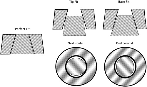
‘Perfect fit’: no angular mismatch between the stem taper and the taper adaptor.
‘Tip fit’: angular mismatch causes the taper adaptor to seat proximally.
‘Base fit’: angular mismatch causes the taper adaptor to seat distally.
‘Oval frontal’: a perfect fit in the superior-inferior (SI) direction and an angular mismatch in the anterior-posterior (AP) direction.
‘Oval coronal’: a perfect fit in the AP direction and a mismatch in the SI direction.
In addition, the angular taper mismatch was reduced by 50% for each of these scenarios in order to evaluate the effect of the magnitude of the taper mismatch. The resulting angular mismatch, based on the tolerances described in ISO 2768-1:1989, on the male taper was 1.27° for the full and 0.64° for the half mismatch. The female taper on the adaptor was kept constant.
Wear model
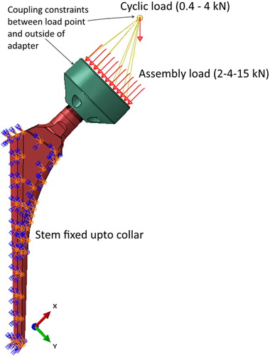
Wear was simulated using adaptive meshing based on Archard’s law, as previously described in (Bitter et al. Citation2018). The wear depth was calculated following H = kpS, in which H is the wear depth (mm), k is the wear factor (mm³/Nmm), p is the contact pressure (MPa) and S is the sliding distance (mm). The geometry of the stem was updated by moving each node perpendicular to the surface using the UMESHMOTION subroutine (Abaqus 2017, Dassault Systèmes, Vélizy-Villacoublay, France), according to the calculated wear depth. The loads on the model were based on previous fretting experiments; the stem was fixed in accordance with ISO 7206-6:2013, the adaptor and stem were assembled using 2, 4 or 15 kN force perpendicular to the taper axis (). A cyclic load between 0.4 and 4 kN was applied oriented as described in ISO 7206-6:2013. The wear was updated after each change in load for every cycle (both after reaching 0.4 and 4 kN). 50 virtual steps were modeled mimicking 10 million experimental cycles, linearly accelerating the simulation with a factor of 200.000 by scaling the wear factor. This discretization was applied to give optimal results in simulation time and predicted wear. The wear factor used was determined previously (Bitter et al. et al. 2018) at a value of 2.7 × 10⁻⁵ [mm³/Nmm] by matching FE models with experiments.
Figure 2. FE boundary conditions and loads.
Results
The full ‘tip fit’ stem assembled with 2 kN did not numerically converge from the first cyclic load step, most likely due to the poor connection at the top edge of the stem in this situation. Therefore, the results of this simulation have been not been included.
Micromotions and contact pressures
In and the micromotions and contact pressures are plotted for all the mismatch situations assembled with 4 kN. The figures are created at the final 4 kN load, the micromotions are calculated as the contact displacement relative to the previous load of 0.4 kN. As a result of the adaptive meshing these patterns have changed between the first cycle and the last cycle. The areas where the contact pressures and micromotions overlap is the area in which adaptive meshing will take place to simulate the wear. From these figures it can be seen that the overlap in micromotions and contact pressures for the ‘tip fit’ is not situated at the tip, but further down on the inferior side. When the mismatch was halved, this area moved down even further on the inferior side, resulting in the wear patch also moving down on the inferior side of the stem ().
Figure 3. Micromotion plots for junctions assembled with 4 kN. The darkest red color indicates micromotion values which are above 70 µm.
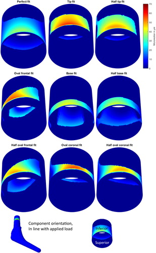
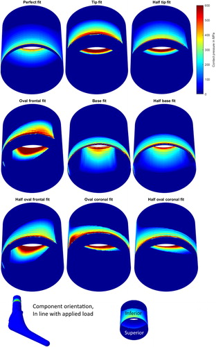
Figure 4. Contact pressures plots for junctions assembled with 4 kN.
For the ‘base fit’ the opposite can be seen. On the superior side the micromotions are higher up on the taper where the largest contact pressures are at the top of the taper. On the inferior side the micromotions and contact pressures are near the base of the taper, the resulting wear patch is shown in .
The micromotion and contact pressure patches for the ‘oval fit’ stems start at the same height on the stem as the ‘tip fit’, however the shape of the contact area is different. The initial contact areas are not in line with the direction of the load, resulting in an almost diagonal contact area.
Plastic deformation
Plastic deformation was not observed in any of the stems during the assembly process. Even though the contact pressures for the ‘base fit’ were above the yield stress of 865 MPa, the (von mises) yield criteria was not reached and plasticity was not present at this point.
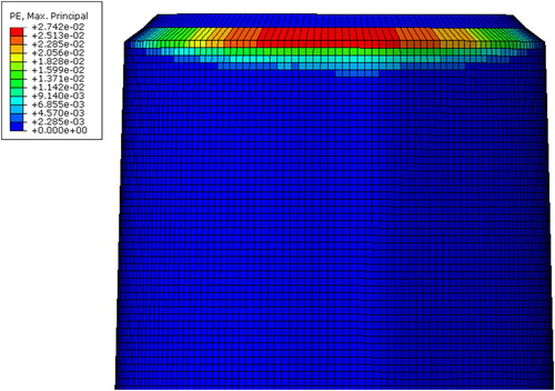
Plasticity was observed after the cyclic loading, mainly in the ‘tip fit’ situations. The largest plastic strain was observed for the ‘tip fit’ assembled with 15 kN, see . The maximum plastic strain was in this case 2.74%, it reduced slightly to 2.67% when assembled with 4 kN. For all other mismatch types the plasticity was considerably smaller. The 'base fit’ assembled with 15 kN had a small plastic patch at the base of the taper, with a maximum plastic strain of 0.35%. The ‘oval’ stems had small plastic patches at the tip, with maximum values of 0.58% and 0.61% for the ‘oval coronal’ and ‘oval frontal’ stems respectively when assembled with 15 kN. The plastic strain decreased in all situations with a lower assembly force.
Figure 5. Plastic strain for 'Tip fit' assembled with 15 kN, and subsequently cyclic loaded, at the end of the simulation.
Wear patterns
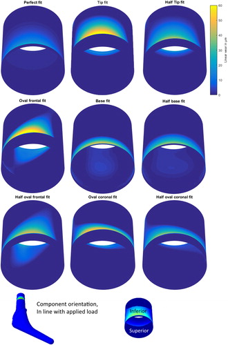
In the wear depth contour plots can be seen for different taper fits assembled with 4 kN after 10 million cycles. All components are orientated in-line with the applied load, displaying the wear patches on the inferior side of the taper. The ‘perfect fit’ had the least wear with the lowest wear depth (26.9 µm), while the ‘tip fit’ had the largest visible “thumbprint” wear patch and the highest wear depth (67.7 µm). The half ‘tip fit’ stem had a wear patch similar to the full ‘tip fit’, but the wear depths were lower (46.2 µm), reducing the total volumetric wear. The ‘base fit’ stems had maximum wear depths of 46.6 µm for the full tolerance and 42.2 µm for the half tolerance.
Figure 6. Wear depth contour plots, after simulation assembled with 4 kN.
Wear rates and total wear
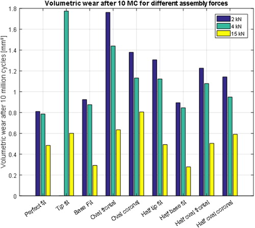
The volumetric wear rates showed relatively high initial wear rates, which decreased after 1 million cycles for all types of taper fit (compare left to right curves in ). The ‘tip fit’ had the highest volumetric wear and wear rates when assembled with 4 kN (as mentioned previously, the 2 kN simulation with a tip fit stem did not converge). The ‘perfect fit’, when assembled with 2 kN or 4 kN, resulted in the lowest wear rates and least amount of total volumetric wear (). The half and full ‘base fit’ stems had a slightly larger wear rate and total volumetric wear than the ‘perfect fit’ when assembled with 2 kN or 4 kN, but performed better when assembled with 15 kN. The volumetric wear was 43% lower with the half ‘base fit’ stem and 40% lower with the ‘base fit’ stem, compared to the ‘perfect fit’ stem assembled with 15 kN. The results for the oval fits were between the results for the tip and base fits, and the ‘oval coronal’ fit had less volumetric wear compared to the ‘oval frontal’ fit.
Figure 7. Initial wear rate up to 1 million cycles (left) and wear rate after 1 million cycles (right) for different tolerances and assembly forces. Lines are connected between 2, 4 and 15 kN assembly force to emphasize the trends found depending on the assembly force.
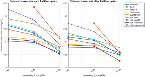
Figure 8. Volumetric wear after 10 million cycles.
Discussion
In the present study the volumetric wear at the taper junction was calculated for different taper mismatches and assembly forces. For low (2 kN) and recommended (4 kN) assembly forces, a ‘perfect fit’ resulted in the least amount of wear. In the case of high assembly forces, the mismatches had less of an effect, with less variation in amount of wear. In this case the ‘base fit’ mismatches had the least amount of wear. The least amount of wear in case of a ‘perfect fit’ can be explained by the contact pressures being spread over the whole interface, rather than a small contact area at the tip or base of the taper. Although this larger contact area seems to lower the wear in the case of a ‘perfect fit’, the opposite is true for the tip and base fit stems. The ‘tip fit’ stem had a larger area in contact, a larger wear patch and more volumetric wear compared to the ‘base fit’ stem. The same was found when comparing the half ‘tip fit’ stem with the full ‘base fit’ stem, which both showing a similar maximum wear depth. The conceptual ‘oval fit’ mismatches had a volumetric wear in between the tip and base fit stems, where the orientation had an effect on the volumetric wear. This can be explained by the orientation of the load being in-line with the contact area of the oval shape, resulting in a larger area where micromotions and contact pressures overlap.
In this work it is shown that the wear is reduced with an increased assembly force. This agrees with the experimental findings of Rehmer et al. (Citation2012) who found that an increased assembly force results in a higher trunnion strength, meaning a larger pull-off force or turn-off moment was required when assembled with a higher assembly force. Assembly forces as high as 15 kN reduced the volumetric wear and volumetric wear rate in every situation. It is, however, unlikely that these high assembly forces will be reached in clinical practice. Furthermore, it is also undesirable, as such a high assembly force could result in a damaged femur. The use of the high 15 kN assembly force in this study is used to show a ‘best case’ scenario for the taper interface. The large spread between the assembly forces help to get a better view of the effect of assembly force on taper wear. Lavernia et al. (Citation2009) found relative low impaction forces of 1.6 ± 0.4 kN, where Nassutt et al. (Citation2006) found higher assembly forces of 3.4 kN, but with a large standard deviation of 2.3 kN. As the assembly force is important for the trunnion strength, the use of an instrumented hammer could be beneficial in order to give surgeons confirmation that they have applied sufficient impaction force.
Compared to other studies, the tolerances in this paper are based on general manufacturing tolerances on the taper diameters, and not on measurements of a single implant system (Rehmer et al. Citation2012) or measurements from new and retrieved implants of a single manufacturer (Langton et al. Citation2012; Brock et al. Citation2015; Langton et al. Citation2017). This results in larger tolerances than measured or found in retrieved systems. Although it is unlikely that such high deviations are manufactured, the tapers would be within specifications. It has been shown that mixing and matching of different components from different manufacturers can result in mismatches, with an increased risk of failure (Chana et al. Citation2012). Even though the angular mismatch in this study is relatively large, a component mismatch of 1.69°, with a Type-1 stem and a 12/14 head, would result in an even larger mismatch. Gührs et al. (Citation2017) described that this type of mismatch is not easily detected visually during surgical assembly, and that mismatched taper/heads result in about 50% lower fracture loads in case of a ceramic head. Both these situations, mixing and matching of components of different manufacturers, and of different taper types, could lead to larger mismatches than currently found on retrieved systems where components are used as intended. The current results show that it is important to minimize taper mismatch, and that it is better to have a ‘base fit’ than a ‘tip fit’. This information may be of value for the manufacturing process of taper junctions in hip arthroplasty components. A recent study of Mueller et al. (Citation2017), among stems and heads from 8 different manufacturers showed, that out of the 8 systems tested 7 had a ‘tip fit’ and only one a ‘base fit’ mismatch.
Other studies have shown mixed results when modeling wear for different taper tolerances. Fallahnezhad et al. (Citation2017) concluded that base fit mismatches are more resistant to fretting wear, while Ashkanfar et al. (Citation2017) found the opposite with base locked tapers having significantly larger wear rates. Both studies, however, have different material combinations, taper mismatches and wear models. Ashkanfar et al. uses the dissipated energy wear law for a cobalt chrome on titanium material couple with a maximum mismatch of 0.18° in a 3 D FE model. Fallahnezhad et al. uses a 2 D wear model based on Archard’s law for cobalt chrome on cobalt chrome material couples with a maximum mismatch of 0.124°. Both studies used a 4 kN assembly force and larger taper angles, 5.6° versus our 4°. The differences in these results could possibly be explained by the different material couples, wear models or the magnitude of the taper mismatch. The variation in outcomes of computational models simulating taper fretting illustrate the importance of model validation against experimental results, which we have done in our previous work (Bitter et al. Citation2018).
In the current study volumetric wear was calculated as the amount of volume lost due to the movement of the nodes. There is, however, also a change in geometry due to plastic deformations. Plastic deformation was mainly observed in the ‘tip fit’ stems, and hardly in any of the other cases. The volumetric material loss for the ‘tip fit’ stems might therefore be underestimated, when compared to experimental measurements of taper junctions.
Although the loading in the current study was simplified, it was based on an experimental set up from a previous study, which was used to mimic wear patterns found on retrieved components, to ensure a clinically relevant loading regime.
In this study Archard’s law is used to model wear. This model is limited to wear based on contact conditions, sliding distances and material constants like the hardness. As a result, a limitation of this model is that only mechanical wear is modeled. Electrochemical processes may have an additional effect on the wear at the taper interface (Goldberg and Gilbert, Citation2003), so the current simulations may have underestimated the actual wear volume. Areas at which there are very low contact pressures and high micromotions now result in very low, or no wear. These conditions might be sensitive to electrochemical processes, such as crevice corrosion. Recently Fallahnezhad et al. (Citation2018) developed an FE model in which fretting corrosion at a simplified metallic interface was modeled. When applied to the taper interface, this model could give improved insights into the wear at the taper interface of modular total hip arthroplasties.
In addition to the previous limitation, no 3rd body wear as a result of wear debris particles or contamination was included, which may accelerate the wear process. Archard’s law is not capable of including these factors. Additions to the used wear model could therefore result in more accurate wear predictions.
Although for a Ti6Al4V-Ti6Al4V stem-adapter couple a ‘base fit’ was found to result in the least amount of wear, this is not necessarily the best option for all material couples. More brittle materials, such as ceramics, are more susceptible to fracture than metal components. The fracture risk of ceramics is greatly increased by the taper contact region, caused by the type of mismatch or taper offset, the taper roughness, and the taper straightness (Heimke Citation1994; Cales and Stefani Citation1998). A ‘base fit’ taper mismatch increases the risk of ceramic head fracture, therefore a ‘tip fit’ is advised in order to reduce the risk of ceramic fracture (Piconi and Maccauro Citation1999).
Conclusions
This study showed that a ‘perfect fit’ between a Ti6Al4V stem and Ti6Al4V taper adaptor in combination with a large assembly force results in the least amount of wear. However, it is not practical to manufacture tapers to perfectly match. With this in mind, this study showed that a ‘base fit’ mismatch is preferable over a ‘tip fit’ mismatch, resulting in only slightly higher wear than a ‘perfect fit’ for Ti6Al4V components.
Furthermore, this study showed that an increase in assembly force reduces wear, and therefore sufficient force should be used when assembling the implant system.
Disclosure statement
No potential conflict of interest was reported by the author(s). Authors Imran Khan, Tim Marriott and Elaine Lovelady are employees of Zimmer Biomet.
Additional information
Funding
References
- Ashkanfar A, Langton DJ, Joyce TJ. 2017. A large taper mismatch is one of the key factors behind high wear rates and failure at the taper junction of total hip replacements: a finite element wear analysis. J Mech Behav Biomed Mater. 69:257–266.
- Ashkanfar A, Langton DJ, Joyce TJ. 2017. Does a micro-grooved trunnion stem surface finish improve fixation and reduce fretting wear at the taper junction of total hip replacements? A finite element evaluation. J Biomech. 63:47–54.
- Bitter T, Khan I, Marriott T, Lovelady E, Verdonschot N, Janssen D. 2018. Finite element wear prediction using adaptive meshing at the modular taper interface of hip implants. J Mech Behav Biomed Mater. 77:616–623.
- Bitter T, Khan I, Marriott T, Schreurs BW, Verdonschot N, Janssen D. 2016. Experimental measurement of the coefficient of friction at the Ti-Ti taper connection in total hip arthroplasty. J Biomech Eng. 138:4032446.
- Brock TM, Sidaginamale R, Rushton S, Nargol AV, Bowsher JG, Savisaar C, Joyce TJ, Deehan DJ, Lord JK, Langton DJ. 2015. Shorter, rough trunnion surfaces are associated with higher taper wear rates than longer, smooth trunnion surfaces in a contemporary large head metal-on-metal total hip arthroplasty system. J Orthop Res. 33(12):1868–1874.
- Cales B, Stefani Y. 1998. Risks and advantages in standardization of bores and cones for heads in modular hip prostheses. J Biomed Mater Res. 43(1):62–68.
- Chana R, Esposito C, Campbell PA, Walter WK, Walter WL. 2012. Mixing and matching causing taper wear: corrosion associated with pseudotumour formation. J Bone Joint Surg Br. 94:281–286.
- Delaunay C, Petit I, Learmonth ID, Oger P, Vendittoli PA. 2010. Metal-on-metal bearings total hip arthroplasty: the cobalt and chromium ions release concern. Orthop Traumatol Surg Res. 96(8):894–904.
- Donaldson FE, Coburn JC, Siegel KL. 2014. Total hip arthroplasty head-neck contact mechanics: a stochastic investigation of key parameters. J Biomech. 47(7):1634–1641.
- Dyrkacz RMR, Brandt JM, Morrison JB, O’ Brien ST, Ojo OA, Turgeon TR, Wyss UP. 2015. Finite element analysis of the head-neck taper interface of modular hip prostheses. Tribiol Int. 91:206–213.
- Elkins JM, Callaghan JJ, Brown TD. 2014. Stability and trunnion wear potential in large-diameter metal-on-metal total hips: a finite element analysis. Clin Orthop Relat Res. 472(2):529–542.
- Fallahnezhad K, Farhoudi H, Oskouei RH, Taylor M. 2016. Influence of geometry and materials on the axial and torsional strength of the head-neck taper junction in modular hip replacements: a finite element study. J Mech Behav Biomed Mater. 60:118–126.
- Fallahnezhad K, Oskouei RH, Badnava H, Taylor M. 2017. An adaptive finite element simulation of fretting wear damage at the head-neck taper junction of total hip replacement: the role of taper angle mismatch. J Mech Behav Biomed Mater. 75:58–67.
- Fallahnezhad K, Oskouei RH, Badnava H, Taylor M. 2019. The influence of assembly force on the material loss at the metallic head-neck junction of hip implants subjected to cyclic fretting wear. Metals (Basel). 9(4):422.
- Fallahnezhad K, Oskouei RH, Taylor M. 2018. Development of a fretting corrosion model for metallic interfaces using adaptive finite element analysis. Finite Elem Anal Des. 148:38–47.
- Goldberg JR, Gilbert JL, Jacobs JJ, Bauer TW, Paprosky W, Leurgans S. 2002. A multicenter retrieval study of the hip prostheses. Clin Orthop Relat Res. 401:149–161.
- Goldberg JR, Gilbert JL. 2003. In vitro corrosion testing of modular hip tapers. J Biomed Mater Res. 64:78–93.
- Gührs J, Körner M, Bechstedt M, Krull A, Morlock MM. 2017. Stem taper mismatch has a critical effect on ceramic head fracture risk in modular hip arthroplasty. Clin. Biomech. 41:106–110.
- Heimke G. 1994. The safety of ceramic balls on metal stems in hip arthroplasty. Adv Mater. 6(2):165–170.
- Higgs GB, Hanzlik JA, MacDonald DW, Gilbert JL, Rimnac CM, Kurtz SM. 2013. Is increased modularity associated with increased fretting and corrosion damage in metal-on-metal total hip arthroplasty devices? A retrieval study. J Arthroplasty. 28(8):2–6.
- Hozack WJ, Mesa JJ, Rothman RH. 1996. Head-neck modularity for total hip arthroplasty: Is it necessary? J Arthroplasty. 11(4):397–399.
- Kocagöz SB, Underwood RJ, Sivan S, Gilbert JL, MacDonald DW, Day JS, Kurtz SM. 2013. Does taper angle clearance influence fretting and corrosion damage at the head-stem interface? A matched cohort retrieval study. Semin Arthroplasty. 24(4):246–254.
- Langton DJ, Ahmed I, Avery P, Bone M, Cooke N, Deehan D, Duffy P, Foguet P, Green S, Holland J, et al. 2017. Investigation of taper failure in a contemporary metal-on-metal hip arthroplasty system through examination of unused and explanted prostheses. J Orthop Res. 99(5):427–436.
- Langton DJ, Sidaginamale R, Lord JK, Nargol AVF, Joyce TJ. 2012. Taper junction failure in large-diameter metal-on-metal bearings. Bone Jt Res. 1(4):56–63.
- Lavernia CJ, Baerga L, Barrack RL, Tozakoglou E, Cook SD, Lata L, Rossi MD. 2009. The effects of blood and fat on Morse taper disassembly forces. Am J Orthop (Belle Mead NJ). 38:187–190.
- Lavernia CJ, Iacobelli DA, Villa JM, Jones K, Gonzalez JL, Jones WK. 2015. Trunnion-head stresses in THA: are big heads trouble? J Arthroplasty. 30(6):1085–1088.
- Mueller U, Braun S, Schroeder S, Sonntag R, Kretzer JP. 2017. Same but different? 12/14 Stem and head tapers in total hip arthroplasty. J Arthroplasty. 32(10):3191–3199.
- Nassif N. A, Nawabi DH, Stoner K, Elpers M, Wright T, Padgett DE. 2013. Taper design affects failure of large-head metal-on-metal total hip replacements. Clin Orthop Relat Res. 472(2):564–571.
- Nassutt R, Mollenhauer I, Klingbeil K, Hennig O, Grundei H. 2006. Die bedeutung der setzkraft f??r die sicherheit einer konuskopplung von H??ftstiel und keramischem prothesenkopf. Biomed Tech. 51(2):103–109.
- Piconi C, Maccauro G. 1999. Zirconia as a ceramic biomaterial. Biomaterials 20(1):1–25.
- Rehmer A, Bishop NE, Morlock MM. 2012. Influence of assembly procedure and material combination on the strength of the taper connection at the head-neck junction of modular hip endoprostheses. Clin Biomech. 27(1):77–83.
- Srinivasan A, Jung E, Levine BR. 2012. Modularity of the femoral component in total hip arthroplasty. J Am Acad Orthop Surg. 20(4):214–222.
- Swann RP, Webb JE, Cass JR, Van Citters DW, Lewallen DG. 2015. Catastrophic head-neck dissociation of a modular cementless femoral component. J bone Jt Surg. 5:1–5.
- Theodorou EG, Provatidis CG, Babis GC, Georgiou CS, Megas PD. 2011. Large diameter femoral heads impose significant alterations on the strains developed on femoral component and bone: a finite element analysis. Open Orthop J. 5:229–238.
- Werner PH, Ettema HB, Witt F, Morlock MM, Verheyen CCPM. 2015. Basic principles and uniform terminology for the head-neck junction in hip replacement. HIP Int. 25(2):115–119.