
1. Introduction
Micro-air vehicles (MAVs) are able to fly at Reynolds numbers from 103 to 105, where the conventional fixed and rotatory wings present reduced aerodynamic performance due to the increased importance of flow viscous forces with respect to inertial forces. Therefore, observation of nature brought a possible solution to this problem. Much of the beauty of living creatures may reside in the enigma behind their functioning. Due to the observation of the stunning flight of insects and small birds, flapping wings appear as a possible alternative to the conventional wing concepts, offering several advantages such as enhanced aerodynamic performance at low Reynolds number and increased flight agility (Dickinson et al. Citation1999; Birch & Dickinson Citation2001). This could lead to a generation of high aerodynamically efficient MAVs.
However, further research is required to be able to understand all the aspects of this type of flight. With this study, the aim is to identify the flapping conditions that provide the best performance. To do so, different parameters of the flapping motion, such as angle of attack of upstroke and downstroke, direction of rotation, time of acceleration, etc., will be studied. Here, the optimization of the upstroke/downstroke angle of attack will be presented, as well as the validation of the methods used for this research.
2. Methods
2.1. Experimental tests
The experimental tests were performed in a water tank made of Altuglas with an octagonal section and dimensions of 1 m × 1 m × 1.5 m. The different wings are attached at their root by a pivot joint, allowing the rotation along the spanwise axis. This enables the modification of the angle of attack (α). At the same time, the pivot joint is fixed into a vertical axis that allows the revolving motion (ψ) in a horizontal plane. The flapping motion to mimic corresponds to a wing with a NACA0012 profile with a 1 cm chord and 4 cm span flapping in the air at a Reynolds number of 1,000 and a frequency of 10.18 Hz. At the start (ψ = −60°) or end (ψ = 60°) of the upstroke/downstroke, the wing is subjected to both rotating and acceleratingdecelerating phases. After the supination or pronation, the airfoil undergoes a constant velocity revolution phase with a fixed angle of attack. This same configuration was used in Diaz et al. (Citation2018), as well as the procedure for the PIV acquisition.
2.2. Numerical simulations
As it would require a large amount of time and tests to perform all the desired conditions, a numerical model of the NACA0012 wing undergoing the motion tested during the experiments was developed. The Navier-Stokes equations are directly solved using a finite volume method with StarCCM+. The highresolution model grid consists of 35 million polyhedral cells, with a grid spacing of 0.005c in the closer region of the wing. An overset mesh approach is implemented that allows the wing mesh to move in a fixed background mesh. Pressure Dirichlet conditions are applied on the upstream and downstream boundaries of the background mesh, while side boundaries are treated as slip walls. Second order schemes are used for both spatial and temporal discretization. This model is comparable to that addressed in Jardin et al. (Citation2012). A low-resolution model, that consists of 0.5 million cells with a grid spacing of 0.02c in the vicinity of the wing, allows to test a high number of parameters in a reduced period of time, keeping a good enough accuracy of the results (maximum error of 5%). This way, we are able to study the motion performance for the different parameters and see what the optimized configuration would be. Then, the full resolution simulation as well as an experimental test of this final configuration will be carried out to verify the results.
3. Results and discussion
Results obtained from experiments and simulations are analyzed in terms of flow structure and aerodynamic performances. The visualization of the flow structures is performed by application of local criteria such as ω vorticity and Q criterion. However, non-dimensional parameters are shown using the velocity (Vt) at the reference plane (75% span of the wing) and the chord (c). Then, the wing vertical force in hovering flight and the power loading (ratio of the vertical force to the power used for the revolution and rotation of the wing) are used to evaluate the aerodynamic performance.
The experimental acquisition of 25 flapping periods was performed, obtaining the phase-averaged flow in established conditions. The tests allowed us to identify the typical vortical structures (Jardin et al. Citation2012) of this type of motion: leading edge vortex (LEV), tip vortex (TV) and trailing edge vortex (TEV). illustrates the experimental results obtained at two different positions of the flapping period (left), comparing them with numerical simulations (right).
Figure 1. Isosurfaces of Q/(Vt/c)2 = 7.375 coloured by non-dimensional vorticity magnitude (wc/Vt).
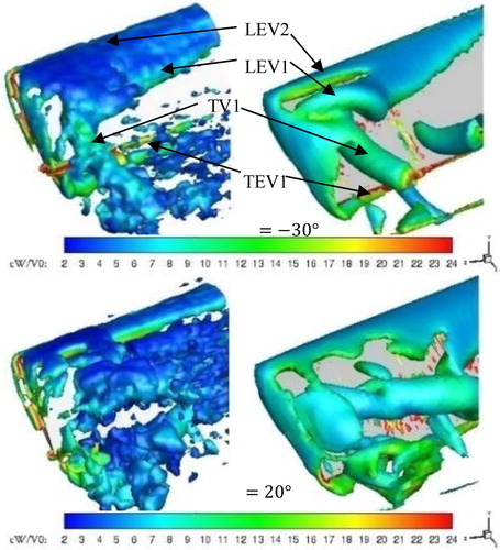
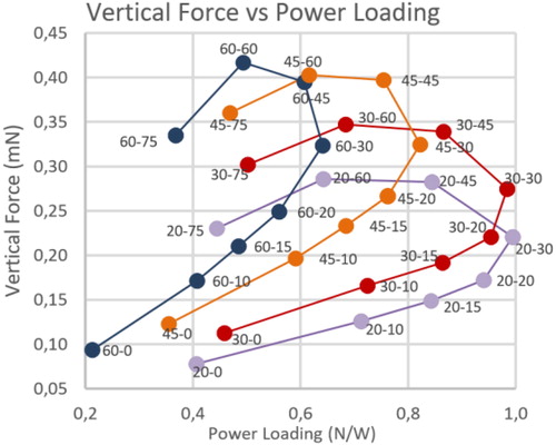
Due to the similarity of the flow structures obtained both numerically and experimentally, and the similarity of the forces generated by the wing, the numerical model is validated allowing to perform the optimization study. The upstroke/downstroke angle of attack is the first parameter analyzed. Upstroke angles from 0° to 75° and downstroke angles from 20° to 60° were tested to see the configuration that gave the best performance. Results of these simulations are illustrated in . The graph shows how the vertical force increase with the upstroke angle surprisingly up to 60°, and it decreases for the last case of 75°. In the other hand, the upstroke angle that maximizes the power loading is 30°, having a total maximum with a downstroke angle of 20°. Finally, the best performance requires maximum vertical force and power loading, so the angles to consider are 45°45°, 30°−45° and 30°−30°, depending if the case requires greater vertical force or power loading.
Figure 2. Vertical force vs Power loading for all the downstroke/upstroke angles computed in StarCCM+.
4. Conclusions
The ongoing study will allow to identify the flapping motion configuration that gives the best performance. For now, the characterization of the fluid around the wing in motion has been achieved, as well as the optimization of the upstroke and downstroke angles of attack. Soon, other parameters of the flapping motion will be studied such as the acceleration-deceleration times and direction of rotation.
Acknowledgements
This project has received funding from the European Union’s Horizon 2020 research and innovation programme under grant agreement No. 769237, HOMER (Holistic Optical Metrology for Aero-Elastic Research). It is also included in the CPER FEDER project of the Region Nouvelle Aquitaine.
References
- Birch JM, Dickinson MH. 2001. Spanwise flow an the attachment of leading edge vortex on insect wings. Nature. 412(6848):729–733.
- Diaz D, Jardin T, Pons F, David L. 2018. Comparison between start-up and established flow conditions in deformable flapping wings. 19th International Symposium of Applications of Laser and Imaging Techniques to Fluid Mechanics.
- Dickinson MH, Lehmann FO, Sane SP. 1999. Wing rotation and the aerodynamic basis of insect flight. Science. 284(5422):1954–1960.
- Jardin T, Farcy A, David L. 2012. Three-dimensional effects in hovering flapping flight. J Fluid Mech. 702:102–125.