
1. Introduction
The hip is considered as the most loaded joint in the human body, it can support up to 4 times the weight of the body. Diseases of this joint have become very widespread and are increasingly affecting younger populations. At their advanced stage, prosthesis remains the best medical solution to repair the damaged joint. To predict early deterioration and increase the lifespan of the prosthetic solutions, it is necessary to study the biomechanical behaviour of the femoral bone tissue. Bone is a tissue, which has capacity for continuous remodelling under the mechanical stimulus. This process plays central role in the context of implants and prostheses placed in it. Possibility of foreseeing the consequences of implant placement on the mechanical fields, and consequently on the process of bone remodelling, is crucial for implant designers. Insertion of non-natural parts with different mechanical properties into the bone leads to a change in stress distribution, and thus can generate the disruption of homeostasis, in which the healthy bone is. Moreover, the repetitive or cyclic loading of bone with evolving properties can yield the fatigue and fracture of the bone tissue surrounding implant. The final aim of this work is to compare the mechanical states of healthy and implanted human femur in order to design the appropriate fatigue testing device and bone sample geometry. Numerous studies of the stress distribution in the femur during human walking can be found in literature (Polgar et al. Citation2003; Abdellatif and Benaoumeur Citation2016). However in our knowledge, the risk of cortical bone fatigue in vicinity of the implant was neither considered. In this paper, the first results concerning the stress distribution in healthy and implanted femurs are presented. The bone geometry, loading, boundary conditions and mechanical properties have been deduced from OpenSIM simulations of gait cycle and µCT scanning of the human femur.
2. Methods
The geometric model of the human femur was developed from the tomographic data obtained using Scanco Medical apparatus (resolution 3 µm). After their binarization into cortical and spongy tissues, the
Finite Element (FE) model of the bone was built using the HyperMesh software. The mesh reproduces both types of bone-cortical and spongy. The thickness of the cortical bone varied from 0.5 mm at the femoral neck to 7 mm at the distal part. The target size of the elements was 1.5 mm to guaranty a good quality mesh that is composed of 123500 nodes and 627870 four node tetrahedral elements. The obtained mesh of healthy femur is shown in . After consultation of surgeons the head of the femur (upper epiphyseal region) was suppressed and titanium implant was positioned in the bone. shows the relative position of the implant with respect to the bone external surface and its medullar canal. The implant is discretized using hexahedral elements. Its mesh is composed of 26585 nodes and 24500 elements of 1.5 mm size. Consequently, the mesh of the implanted femur is mixed containing the tetrahedral and pyramidal elements of bone tissues and hexahedral elements of implant. In order to smooth the action of muscular forces applied to the bone, layers of pentahedral elements were locally expended in the muscular attachment regions of the femur. The typical elastic properties were attributed to the titanium implant (E = 105 000 MPa and ν = 0.3).
Figure 1. (a) Mesh of healthy femur (b) implant position.
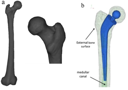
The elastic properties of bone elements were deduced from the CT data using the algorithm proposed in Dieter and Philippe (Citation2009). The properties of the cartilage and ligaments were taken from the literature (Chen et al. Citation1996). The boundary conditions correspond to the contact between the pelvis and the femoral head or between the male and female parts of the prosthesis used. The reaction of the knee joint was applied in the rotation centre of the joint and treated as an external force associated with the muscular actions. These forces were obtained from the inverse kinematic simulation of the gait cycle using OpenSim software. To deduce the muscular force directions we have used the plug-in “Muscle Force Direction” proposed by Phillips, Villette, and Modenese (Citation2015). It provides the current position of muscular attachments and the forces’ direction of the muscles introduced to the model. In this study the model of human skeleton developed by Delp et al. (Citation2007) was used to simulate the gait cycle. 29 muscles are attached to the femur. Their actions were transformed to the femur coordinate system. They were applied during 1.5 s interval corresponding to the right leg motion and its contact with the ground leading to the most intense stress state in the bone.
3. Results and discussion
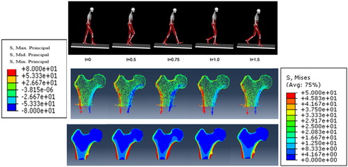
The partial results are presented in showing the maps of principal values and directions of stress tensor and von Mises stress. They are given for five leg positions depicted in first line of . They were extracted from the OpenSim results (Delp et al. Citation2007). The second and third lines give the stress distribution in the vicinity of the femoral head. To compare the results the same presentation was done for implanted bone (not shown in this paper).The mechanical fields strongly depend on the interactions taken into account. Two cases were studied namely the perfectly osseo-ntegrated and the non-integrated implant in mechanical contact with the femur. The case of simple contact between the femur and the implant introduces much more severe stress state in the vicinity of the implant stem. It generates the stress field that can be assimilated to the local cylindrical indentation or punching inducing the high tension stresses in the adjacent cortical layer of the femur. The definitions of the specific geometry of the fatigue samples and holders for the fatigue tests were designed basing on the observed stress fields.
Figure 2. Five positions of the leg during gate and corresponding stress distribution in the femoral head.
4. Conclusions
Average human femoral bone was scanned and its geometry and elastic properties of both types of tissue were deduced from the CT data. The muscular actions corresponding to the gait cycle were calculated using OpenSim software. This procedure enabled creation of the lifelike anisotropic FE models of the healthy and implanted bones. The results of computations show the implant insertion influences the mechanical behaviour of the femur. It induces significant stresses in the vicinity of the implant stem depending on considered interactions between bone and implant. The third case of cemented implant will be treated in the next future.
Additional information
Funding
References
- Polgar K, Gill HS, Viceconti M, Murray DW. 2003. Proc Inst Mech Eng H. 217(3):173–189. Volume: issue: page(s):
- Abdellatif R, Benaoumeur A. 2016. Communication Science & technology. 16.
- Dieter H, Philippe K. 2009. Computer Methods in Biomechanics and Biomedical Engineering. 12(1):45–57.
- Chen EJ, Novakofski J, Jenkins WK, O'Brien WD. 1996. IEEE transactions on ultrasonics. IEEE Trans Ultrason Ferroelect Freq Contr. 43(1):191–194.
- Phillips ATM, Villette CC, Modenese L. 2015. Femoral bone mesoscale structural architecture prediction using musculoskeletal and finite element modelling. Int Biomech. 2(1):43–61.
- Delp SL, Anderson FC, Arnold AS, Loan P, Habib A, John CT. 2007. IEEE Transactions on Biomedical Engineering. 55:1940–1950.