
1. Introduction
Inertial measurement units (IMUs) are extensively used today for different clinical applications, gait event detection, fall detection, or physical activity analyse. Compared to the gold standard, the optoelectronic system, IMUs do not require a laboratory environment. Consequently, IMUs seem to constitute the best alternative for movement analysis in natural environment or daily living conditions. IMUs are composed of accelerometers, gyroscopes, and, most often, magnetometers. Data fusion with a Kalman or complementary filter provides the orientation of the IMUs in a global coordinate system. An important prerequisite for human movement analysis is to define the IMU orientation relatively to the human segment on which the IMU is fixed (Picerno Citation2017), which is achieved by defining the segment axes in the IMU coordinate system. In the literature, different methodologies have been presented. The static calibration method proposes to define the segment axes based on one or several static poses (Vargas-Valencia et al. Citation2016). The hypothesis is that the segment axes are aligned with the vertical and/or horizontal, depending on the pose taken by the segments. This method is fast to apply but the real body’s segment alignment is not ensured. Another method is the anatomical calibration which uses a device to locate in the IMU coordinate system anatomical landmarks on which the axes are based (Picerno, Cereatti, and Cappozzo Citation2008). This method is repeatable but needs a specific device to locate anatomical landmarks. The last method is the functional method (O’Donovan et al. Citation2007). The subject performs movements during which the segment rotation axis is defined. This method is also repeatable but is strongly dependant on the subject’s ability to perform pure rotation around the functional axis to define. To our knowledge, no functional or anatomical method has been proposed for the pelvis. Now, the pelvis is also an important segment for movement analysis. The pelvis coordinate system definition has indeed an incidence on pelvis kinematics but also on hip kinematics since the hip kinematics are obtained by defining the movement of the thigh coordinate system relatively to that of the pelvis.
The aim of the present study is then to compare different calibration methods to obtain the pelvis coordinate system relatively to that of the IMU. We will test a static method, a functional calibration method, and an original method that also makes use of a calibrating device.
2. Methods
Nine healthy subjects, five males and four females, participated in this study. Seven IMUs (opal, APDM, Portland, USA) cadenced at 256 Hz were positioned on the sacrum and on each thigh at a mid-lateral location. The IMU orientations were obtained from the constructor algorithm (APDM, Portland, USA). An optoelectronic system composed of 16 cameras cadenced at 250 Hz (Qualisys, Götborg, Sweden) was also used to track twenty reflective markers placed on anatomical landmark in accordance with the Conventional Gait Model marker set. The pelvis device was composed of four linked rigid segments that could be positioned to form a plan based on the left and right anterior and posterior iliac spines. This device was also equipped with an inertial sensor.
Pelvis and hip joint axes were defined in the IMU coordinate systems with three different methods. An exclusively static method S; an exclusively functional method F; a mixed method based on the static corrected by the device for the longitudinal pelvis axis and functional for the others. presents the pose and movements performed during the calibration trials and the axes deduced.
Table 1. Segment axes (medio-lateral ML, antero-posterior AP, longitudinal L) deduced for the different calibration methods.
For the optoelectronic system, the pelvis coordinate system is defined based on the Conventional Gait Model. The hip joint centre is obtained by a combination of hip movements (Halvorsen Citation2003) and the knee joint centre by a combination knee movements (Ehrig et al. Citation2007).
In order to compare methods, all subjects performed additional ten squats with a hip abduction of 30° degrees. The pelvis and hip angles were then computed following the recommendations of the ISB. In order to compare the calibration methods, the Root Mean Square Error (RMSE) was calculated between the pelvis and hip kinematics obtained with the optoelectronic method and with the three methods based on IMUs. A Friedman test was then run on the RMSE to assess the differences between the methods. A Wilcoxon test was then used as post-hoc test.
3. Results and discussion
As reported in , there is a significant difference between methods for pelvis tilt and for hip kinematics (p < 0.05). According to the Wilcoxon tests, the error was greater for the F than for the S and M methods for the pelvis tilt and hip flexion whereas the errors on hip abduction and rotation were greater for the S method than for the F and M methods. Therefore, the mixed method M seems better to obtain the pelvis and hip kinematics. With the F method, the definition of the pelvis AP axis by the use of hip abduction/adduction seemed particularly inefficient.
Figure 1. Boxplots of RMSE of all subjects for the different calibration methods during squats performed with a hip abduction of 30°.
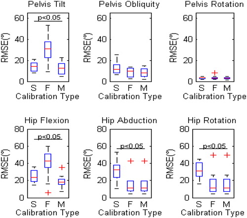
With the M method, the results are unfortunately not completely satisfying since the RMSE remained superior to 10° for most of the kinematics.
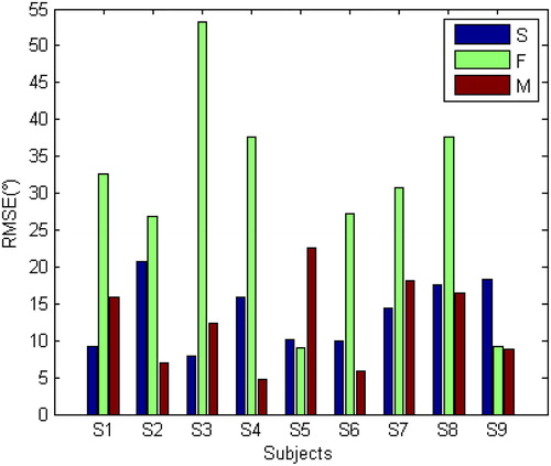
The M method was originally proposed to improve the definition of the pelvis L axis. shows that, unfortunately, the use of this device did not always succeed. For some subjects, the RMSE obtained with the M method was greater than for the S method. This might be explained by the difficulty of device installation.
Figure 2. RMSE of all subjects for the different calibration methods (Static (S), Functional (F), Functional with device (D)) for pelvis tilt during squats with a hip abduction of 30°.
4. Conclusions
The best solution to calibrate the orientation of the IMUs relatively to the pelvis and thigh segments seemed to be a mixed method. The use of a device seems indeed to be a promising solution to improve the pelvis L axis definition but its installation must be further investigated.
References
- Ehrig RM, Taylor WR, Duda GN, Heller MO. 2007. A survey of formal methods for determining functional joint axes. J Biomech. 40(10):2150–2157.
- Halvorsen K. 2003. Bias compensated least squares estimate of the center of rotation. J Biomech. 36(7):999–1008.
- O’Donovan KJ, Kamnik R, O’Keeffe DT, Lyons GM. 2007. An inertial and magnetic sensor based technique for joint angle measurement. J Biomech. 40(12):2604–2611.
- Picerno P. 2017. 25 Years of lower limb joint kinematics by using inertial and magnetic sensors: a review of methodological approaches. Gait Post. 51:239–246.
- Picerno P, Cereatti A, Cappozzo A. 2008. Joint kinematics estimate using wearable inertial and magnetic sensing modules. Gait Post. 28(4):588–595.
- Vargas-Valencia L S, Elias A, Rocon E, Bastos-Filho T, Frizera A. 2016. An IMU-to-body alignment method applied to human gait analysis. Sensors (Basel, Switzerland). 16(12):2090.