
1. Introduction
The socket/residuum interface is a key component in the determination of the success of transfemoral (TF) prosthesis fitting. However, fitting of the socket is still based on the expertise of the prosthetist and femur motion, relative to the socket was highlighted to be of importance for the outcome of the acceptance of the prosthesis (Radcliffe Citation1977). Few studies have measured the movement of the femur relative to the socket. For example, Dynamic Roentgen Stereogrammetric Analysis was used to measure vertical motion during gait (Papaioannou et al. Citation2009). This technique, although accurate, is highly irradiant. Erikson and James (Citation1973) used X-rays to look at the relative position of the femur in different leg positions mimicking gait but X-rays are difficult to use in dynamic situations (Erikson and James Citation1973). Ultrasound, on the other hand, has no known side effects and can be used for dynamic movements, but makes the experimental set up complicated. An ultrasound study has measured the movement of the femur relative to the socket during gait in one subject but ultrasound requires a specific socket (Convery and Murray Citation2000). Tang et al. (Citation2015), have attempted to model the relative movement between the femur and the socket using 3D motion capture only. However, the hip joint center for their model was estimated using a regression equation which is only accurate to 1.07 cm (Bell et al. Citation1990).
The present study combines low-dose bi planar X-rays with 3D motion capture to obtain a subject-specific 3D model of transfemoral amputated subjects and multibody kinematics optimization is used to obtain a prediction of the movement of the femur relative to the socket during gait.
2. Methods
2.1. Subjects
Following the protocol approved by the Ethics Committee (Comité de Protection des Personnes, CPP NX06036), 5 male left transfemoral amputated subjects participated in this study.
2.2. 3D Motion capture
63 optoelectronic markers were placed on the subjects’ bodies. Acquisition of markers locations in time was done with an optoelectronic motion capture system composed of 13 cameras (Vicon) at 100 Hz. Subjects were asked to walk across the room at self-selected speed on a plane surface.
2.3. Low-dose bi-planar radiography
Patients underwent whole-body EOS radiography in the upright position (EOS®, EOS-Imaging, France), with the markers from the 3D motion capture still in place. This was followed by 3D reconstruction of the pelvis and femur on which anatomical frames were based. Relative position of markers to anatomical landmarks was also obtained for modelling.
2.4. Multibody kinematics optimization
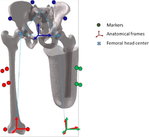
Four markers per segment were used to build and track the socket and the pelvis frame. A residual femur was then generated with the center of the femoral head positioned using the bi-planar radiographies. A ball- and-socket kinematic constraint of the hip was used to reconstruct the kinematics of the femur using a multibody kinematics optimization procedure (Lu and O’Connor Citation1999) ().
Figure 1. Illustration of the residual femur, socket and pelvis and their anatomical frames.
2.5. Data processing
The kinematics of the femur relative to the socket were computed using a zxy mobile axis sequence and interpreted in the femur anatomical frame.
3. Results and discussion
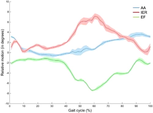
Across our five subjects, were obtained a mean range of motion of 4.4° ± 1° for AA, of 5.9° ± 1° for EF and of 5.6° ± 1.5° for IER (mean ± SD). shows the shape of the curves for one subject. Our results obtained are in line with those of the literature. An X- ray study in 25 subjects found a mean angulation change of 4.8° with, however, variations up to 16° within the same subject (Erikson and James Citation1973). An ultrasound study on one subject found higher mobility with a range of motion of 10° for AA and 15° for EF (Convery and Murray Citation2000). Tang and collaborators obtained a model of the femur movement relative to the socket in excess of 10° in EF and less than 4° in AA. The position of the femoral head for their model was, however, only accurate to the centimeter.
Figure 2. Relative kinematic of the virtual femur to the socket for one subject. In blue adduction/abduction (AA), in red internal/external rotation (IER), in green extension/flexion (EF). Mean and one standard deviation corridor.
As highlighted by the aforementioned studies, there is a high variability between results. Many factors are responsible for this variation, such as the shape, fit and alignment of the socket, the length and orientation of the femur in the residual limb and the subject’s way of walking to prevent pelvic drop. It is therefore delicate to compare the results obtained to the literature data but it gives an idea of the magnitude of the femur motion. To the best of our knowledge, no other study has measured internal/external rotation of the femur within the residuum during gait. Our study presents a new method to study the kinematics of the residuum relative to the socket that requires a less irradiating imaging technique and no modification of the socket. It can potentially aid socket fitting and allow further study of residuum/socket kinematics.
4. Conclusion
Measurement of femur motion relative to the socket in gait in TF amputated patients can be a good indicator of prosthesis outcome. Our model, using low dose bi- planar radiography and motion capture, gives a prediction of femur motion (AA, EF, IER) in line with the sparse results found in the literature.
Acknowledgements
This study was financially supported by Proteor. The authors thank the CERAH/INI and Julia Facione from HIA Percy and the patients who participated in the study.
References
- Bell AL, Pedersen DR, Brand RA. 1990. A comparison of the accuracy of several hip center location prediction methods. J Biomech. 23(6):617–621.
- Convery P, Murray KD. 2000. Ultrasound study of the motion of the residual femur within a transfemoral socket during gait. Prosthet Orthot Int. 24(3):226–232.
- Erikson U, James U. 1973. Roentgenological study of certain stump-socket relationships in above-knee amputees with special regard to tissue proportions, socket fit and attachment stability. Ups J Med Sci. 78(3):203–214.
- Lu T-W, O’Connor JJ. 1999. Bone position estimation from skin marker co-ordinates using global optimisation with joint constraints. J Biomech. 32(2):129–134.
- Papaioannou G, et al. 2009. Assessing residual bone- stump-skin-socket interface kinematics of above knee amputees with high accuracy biplane dynamic roentgen stereogrammetric analysis. 55th Annu Meet Orthop Res Soc.:Paper No. 346.
- Radcliffe CW. 1977. The Knud Jansen Lecture: above-knee prosthetics. Prosthet Orthot Int. 1(3):146–160.
- Tang J, McGrath M, Laszczak P, Jiang L, Bader DL, Moser D, Zahedi S. 2015. Characterisation of dynamic couplings at lower limb residuum/socket interface using 3D motion capture. Med Eng Phys. 37(12):1162–1168.