
1. Introduction
Articular cartilage is the tissue covering the surfaces of long bones ensuring smooth motions and facilitating force transmissions in joints. In the context of tissue engineering, many studies focused on molecular analysis of engineered tissues following mechanical stimulation. Only very few reports aimed at providing the course of their mechanical properties over time (O’Conor et al. Citation2013). This is also the case for cartilage micropellets, although this model of cartilage development from mesenchymal stromal cells (MSCs) is considered as the most relevant in vitro model for cartilage formation (Barry et al. Citation2001). Therefore, we have developed a specific experimental device which should allow to assess the overall mechanical properties of micropellets during cartilage generation overtime, without removing them from their culture environment. The present work is aimed at validating this new device to adequately quantify the mechanical properties of microspheres using alginate beads with similar size as cartilage micropellets in a proof-of-concept experiment.
2. Methods
2.1. Samples
Alginate beads were made by dissolving sodium alginate in a 0.15 M NaCl solution at a final concentration of 3% (w/w). The solution was then extruded into 0.1 M CaCl2 solution and alginate beads were kept for complete polymerisation during 24 h.
2.2. Devices
2.2.1. Home-made device
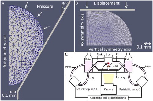
Our home-made device is a fluidic system composed of a 3 D-printed tank, two peristaltic pumps (15KS series, Boxer, Ottobeuren, Germany), a pressure sensor (ADP5161, Panasonic, New York, USA), a camera (Mako, Allied Vision, Stadtroda, Germany) and two arduino cards (Genuino and M0 Pro, Arduino). illustrate how the fluid pressure is applied at the top of the sphere, whereas ground atmospheric pressure is kept at the bottom. Fluid pressure applied at the top causes the sphere to sink into the cone and to deform. The camera is used to measure the displacement of the bottom of the deformed sphere.
Figure 1. Finite elements models and their boundary conditions for conical (A) and planar (B) compression – Scheme of the home-made device (C).
2.2.2. Conventional compression device
In order to estimate the ability of the new setup to quantify the mechanical properties of millimetric spheres, conventional compression tests were carried out (see ). Each alginate bead was placed between two parallel planar surfaces. The lower one was guided by a linear actuator (M-235.52S; Physik Instrumente, Karlsruhe, Germany) the bead against the upper one. A force sensor was used to measure the compression force (Futek Inc., model LSB200, Irvine, USA).
2.3. Mechanical test
One alginate bead was rinsed with distilled water and placed on the planar compression device. A multi-relaxation compression test was made with 8 ramps of 0.025 mm at 0.1 mm/s. The motor displacement was maintained during 30, 60, 90, 90, 120, 120, 150 and 150 s, respectively. 30 min was enough to achieve total recovery. Then, the sample was placed into the new fluidic device. A multi-creep test was made with 6 ramps of 13 ± 1.4 kPa at about 160 kPa/s. Pressure was maintained during 2 min and 10 images were taken. 30 min was enough to attain total recovery. The first compression test (conventional test 1) was then made again (corresponding to the conventional test 2) to check whether the mechanical properties of beads were modified during the time of the experiment.
2.4. Young’s modulus estimation
For conventional compression tests, force and displacement of the lower platen were measured at equilibrium, i.e., when force changed by less than 0.03 mN during 10 seconds. For fluidic compression tests, the pressure and the bottom displacement of the bead were measured at equilibrium (last picture taken by the camera). Two axisymmetric finite element (FE) models employing a neo-Hookean hyperelastic law were used for inverse analysis, one dedicated to the conventional compression test, the other one to the new experimental setup (LMGC90, B). A Poisson’s ratio of 0.4 was chosen (Nguyen et al. Citation2009). A non-linear minimisation procedure (least square procedure from scipy.optimize module, with a Trust Region algorithm, in python) was used to fit each FE model to the experimental data and to determine the corresponding Young’s modulus. The minimisation procedure was based on the use of either the measured force (conventional compression test) or the bottom dispAlacement of the bead (new fluidic system). Paired bilateral T-Tests were used to compare the results of the three mechanical tests.
3. Results and discussion
There was no significant difference (n = 13; p = 0.31) between Young’s moduli obtained from conventional test 1 and those obtained from conventional test 2 (see ). This result indicated that mechanical properties did not change (i.e., no alteration) in relation with the fluidic compression test, which was done after conventional test 1 and before conventional test 2. We could, therefore, compare the mechanical properties obtained from the conventional compression tests to those obtained from the fluidic compression tests.
Young’s moduli obtained from the fluidic compression tests were not significantly different from those obtained from planar compression tests (p = 0.69; p = 0.27, respectively) (). These results showed that the new device allowed to characterise the mechanical properties of small spherical samples in a quantitative manner.
Table 1. Mean and standard deviation of Young’s moduli (kPa) obtained for both testing devices.
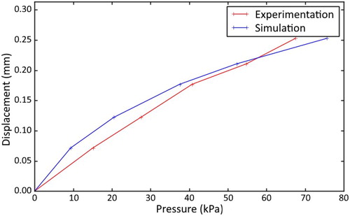
shows a representative fit between the experimental displacement and the simulated one as a function of the applied pressure within the fluidic system. We noted that the model underestimated the stiffness of the alginate bead at low strains (i.e., at low pressure) and overestimated it for higher strains. The same observations were made for conventional compression tests. This might be due to the quite simple hyperelastic law we have chosen, which may not perfectly reproduce the behaviour of alginate beads.
Figure 2. Experimental and simulated displacements of pressure applied at the top of the bead.
4. Conclusion
The new fluidic experimental setup, allowing pressurising microspheres in a conical shape, together with appropriate identification procedure, successfully measured Young’s moduli of millimetric spheres with similar values as conventional compression test. This constitutes a new method to characterise the mechanical behaviour of spherical materials, which will be useful so as to analyse cartilage micropellets and estimate the changes in mechanical properties over long time periods, without removing them from their culture environment. Moreover, unlike other compression devices, this new system allows many micropellets to be loaded at the same time with the same pressure level, regardless of their size.
Acknowledgements
We thank Stephan Devic, Patrice Valorge and Yvan Duhamel for their technical support in developing the fluidic setup.
Additional information
Funding
References
- Barry F, Boynton RE, Liu B, Murphy JM. 2001. Chondrogenic differentiation of mesenchymal stem cells from bone marrow: differentiation-dependent gene expression of matrix components. Exp Cell Res. 268(2):189–200.
- Nguyen VB, Wang CX, Thomas CR, Zhang Z. 2009. Mechanical properties of single alginate microspheres determined by microcompression and finite element modelling. Chem Eng Sci. 64(5):821–829.
- O’Conor CJ, Case N, Guilak F. 2013. Mechanical regulation of chondrogenesis. Stem Cell Res Ther. 4:61.