
 ?Mathematical formulae have been encoded as MathML and are displayed in this HTML version using MathJax in order to improve their display. Uncheck the box to turn MathJax off. This feature requires Javascript. Click on a formula to zoom.
1. Introduction
Bone drilling is a common operation in orthopaedic and dental practices. This operation generates heat resulting mainly from friction between bone hole wall, chips and drill bit body. Heat generation during bone drilling exposes bone cells to elevated temperature and may result in thermonecrosis. Although many experimental investigations have been conducted to characterize the optimal drilling conditions, conclusions are still uncertain and diverging (Pandey and Panda Citation2013). In the present study, a semi- analytical model, based on the moving heat source approach combined with the method of image sources, is developed for predicting the temperature during bone drilling. An experimental drilling campaign on porcine bone samples is conducted in parallel, to validate the model.
2. Methods
2.1. Bone temperature rise prediction model
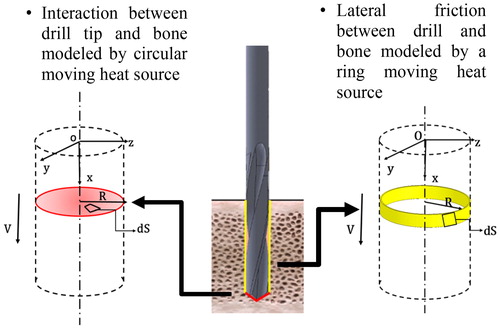
To model the bone temperature rise, two heat sources are considered, see . First the interaction between the drill-bit tip and the bone is modelled as a disk heat source. The second source, due to the friction between the drill-bit side and the hole wall, is assimilated to a finite number of moving ring sources which are activated progressively as the drill-bit body penetrates the bone. The disk heat source is assumed to be equal to a fraction of the mean value of the mechanical energy:
(1)
(1)
where
and
represent respectively the average of the maximum and minimum values of feed force and cutting torque measured experimentally.
is the feed rate,
is the rotational speed and R is the tool radius.
Figure 1. Illustration of the two heat sources considered in the model.
The frictional heat induced by the contact between the drill-bit side and the drilled hole is given by:
(2)
(2)
with
the friction coefficient (=0.3),
the contact pressure and
the cutting velocity
Bone sample is assimilated to a half space. To get the temperature distribution in the semi-infinite medium with adiabatic surface, image source approach is introduced. By using the works of Carslaw and Jaeger (Citation1959), the temperature elevation, at time t, at point M(x, y, z), due to the amount of heat liberated at time t’ at point Q(x', y', z'), by an elementary heat source moving along x-direction with constant velocity V, is given by:
(3)
(3)
The values of thermal conductivity, specific heat and apparent density are respectively (Tu et al. Citation2012): The thermal diffusivity is denoted by a.
The temperature distribution due to the drill-bit tip contribution is obtained by adding the temperature rise due to each elementary heat source over the disk surface. The effect of friction at the drill-bit side is obtained by integrating the elementary heat source over each moving ring progressively activated. Finally, the resulting temperature distribution is given by:
(4)
(4)
with
the initial bone temperature. The values of model parameters
(=0.35) and
(1 MPa) were calibrated with respect to the smallest cutting speed
2.2. Experimental study
The bone samples were obtained by slicing, into lamella of about 70 mm × 10 mm, the diaphysis of a porcine femur provided by a local slaughter. The bone specimens were frozen at −20 °C and they were thawed at ambient temperature 24 hours prior to the tests. Drilling experiments were conducted on a three axes CNC milling machine Roeders RP600. Nobel Biocare REF32271 twist drills with a diameter of 3.2 mm, a helix angle of 30° and point angle of 118° were used. Two K-type thermocouples OMEGA KMTSS-IM025U-150 with a wire diameter of 0.25 mm allowed to measure the temperature elevation inside bone. They were inserted into two holes located at 0.5 mm and 0.9 mm from the hole wall. No lubrication was used. The feed force and drilling moment were also recorded to estimate the heat source at the drill tip (see EquationEquation (1)(1)
(1) ). The measurements were done thanks to a Kistler 9256C2 piezoelectric dynamometer. The drilling experiments were performed by fixing the feed per tooth at 0.02 mm and varying cutting velocities between 2 and 20 m/min at room temperature. The drilling depth was 4 mm.
3. Results and discussion
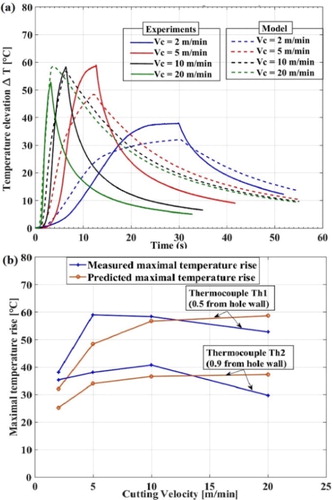
After model calibration, the temperature predicted by the model and obtained by measurement are compared (). Two phases are visible on these curves: the first one corresponding to the increase of temperature during the drilling process and the second one showing the cooling stage. Although some improvements need to be made in order to better describe the cooling phase, the profiles of temperature elevations are globally reproduced by the model. Concerning the comparison of the maximal temperature rises illustrated by , the increase of temperature with cutting velocity from 2 to 10 m/min is properly described. From 10 to 20 m/min, a diminution is observed experimentally while the temperature predicted by the model tends to saturate. These temperature elevations reach values included between 25 and 60 degrees, but no conclusion can be drawn concerning a possible necrosis of bone cells, as no lubrication was taken into account in this work.
Figure 2. (a) Predicted and measured temperature for the thermocouple located at 0.5 mm from hole wall (b) Comparison of maximal temperature elevation.
A constant value of bone apparent density was considered in this model but XRay tomography can be carried out in order to determine the local value of density and adjust the values of thermal properties, according to the variation of bone density. Indeed, the effect of this quantity on heat generation is significant and has to be considered, (Feldmann et al. Citation2017).
4. Conclusions
A semi-analytical model based on the moving heat source approach has been developed to reproduce the bone temperature variation during drilling. Improvements must be made to take into account the influence of bone microstructure on heat generation but the model already provides a good estimation of the temperature rise.
References
- Carslaw HS, Jaeger JC. 1959. Conduction of heat in solids. Oxford University Press.
- Feldmann A, Gavaghan K, Stebinger M, Williamson T, Weber S, Zysset P. 2017. Real time prediction of temperature elevation during robotic bone drilling using the torque signal. Ann Biomed Eng. 45(9):2088–2097.
- Pandey RK, Panda SS. 2013. Drilling of bone: a comprehensive review. J Clin Orthop Trauma. 4(1):15–30.
- Tu YK, Chen LW, Ciou JS, Hsiao CK, Chen YC. 2012. Finite element simulations of temperature rise during bone drilling based on a bone analog. J Med Biol Eng. 33:269–274.