
Keywords:
1. Introduction
During the last decade, the joint developments of measurement devices and software environments advanced biomechanics investigations toward increasingly complex movements performed in ecological conditions. For example, most of the motion analysis systems currently track participants’ movement outdoor in natural light or musculoskeletal software’s make motion analysis and dynamic simulation accessible to a wide range of researchers. OPENSIM (Delp et al. Citation2007), an open-source musculoskeletal software, has become the mainstay in numerous biomechanical studies by providing a full access to source code, and then allowed researchers to extend their capabilities to an infinity of situations.
However, for outdoor sport activities such as rowing, acquisition of the rower’s kinematics on-water is still challenging. Most of rowing biomechanics studies are performed on ergometer while significant differences were observed with on-water conditions (Miarka et al. Citation2018). In other words, rower’s movement on-water must be estimated with another method. The rower’s lower-limb kinematics can be modelled as a closed-loop kinematic chain by assuming that the feet and the pelvis are always in touch with the foot stretchers and the seat, respectively. The aim of this study is to develop a closed-loop multibody model to assess the rowers’ lower-limb kinematics being usable during on-water training sessions with few measurements tools. By this way, we suggest that the kinematics of the hips, knees and ankles can be reasonably estimated via the knowledge of the translation and rotation of the pelvis and feet only. In order to assess the performance of this method, the comparison to a traditional inverse kinematics open-loop method based on data measured with a motion capture system was carried out in laboratory.
2. Methods
Eleven female (age: 26 ± 6 years; mass: 71 ± 6 kg; height: 1.74 ± 0.04 m) and 17 male rowers (age: 23 ± 9 years; mass: 74 ± 6 kg; height: 1.81 ± 0.05 m) participated to an experimentation by performing 45 seconds on a fixed and a free-floating ergometer (RowPerfect, The Netherlands) at 20, 32 and maximal stroke rate. The movements were recorded by 16 optoelectronic cameras (Oqus 7, Qualisys, Sweden) thanks to 40 reflective markers. Participants performed 4 functional movements to calculate lower-limb joints centres of rotation for the ankles, knees (Ehrig et al. Citation2006) and hips (Halvorsen Citation2003). The global frame was defined by anteroposterior (AP), medio-lateral (ML) and vertical axis.
First, a closed-loop lower-limbs chain model (30 relative joint coordinates) was developed with the multibody software ROBOTRAN (Fisette and Docquier Citation2019). This model contained 18 driven, i.e. defined by a specific function of time variables (pelvis (6), feet (6 × 2)) and 12 dependant variables, i.e. solved by an iterative Newtown-Raphton procedure due to non-linearity of the constrainsts (hips (3 × 2), knees (1 × 2) and ankles (2 × 2)). The foot stretchers were separated into an ‘original’ body and a ‘shadow’ body linked by a solid cut to express and then to solve the 6 closed-loop constraints (Fisette and Docquier Citation2019). The limb length was indivually set. A singularity was naturally observed when the knees are fully extended. These associated singular configurations were identified for both the knee flexion/extension and foot stretchers anteroposterior translations. They were shifted for these particular configurations, as driven variables and dependant variables, respectively, to ensure a robust loop closure around and at the knee extension.
Second, an open-loop chain model (20 DOF) was adapted with OPENSIM (Retailleau et al. Citation2018) and scaled for each participant.
Third, two sets of kinematics were computed for the right and left lower-limbs for each participant, each ergometer condition and each stroke rate. The first set was solved with ROBOTRAN using the close-loop constraints and driven variables for both pelvis and knees obtained from the reflective markers. The second set was computed with the classical open-loop inverse kinematics procedure implemented in OPENSIM using the full set of markers as input data. Then, the two sets of kinematics were compared by the mean root mean squared difference (RMSD) for all trials and all participants.
3. Results and discussion
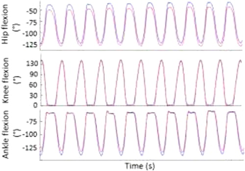
The two sets of kinematics computed with ROBOTRAN and OPENSIM showed differences for each joint whatever the ergometer conditions and stroke rate (). The means RMSD was 8°, 5° and 9° for the flexion of the hips, knees and ankles, respectively, and 11° for the pelvis tilt. Estimated flexions with OPENSIM were larger for the hips and ankles while a difference is observed only at the full extension of the knees.
Figure 1. Flexions for the left hip (top), knee (mid) and ankle (down) calculated with OPENSIM (open-loop, full markers, curves in blue) and ROBOTRAN (closed-loop, limited input, curves in red) for the participant 12 at 20 stroke rate on a fixed ergometer.
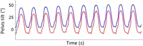
The difference observed for the pelvis tilt accounted for a large part in the difference observed for the hip flexion. To confirm or refute this hypothesis, the pelvis tilt values computed with OPENSIM i) were used as input data with ROBOTRAN, ii) were compared with the absolute pelvis orientation computed with cardan angles from the reflective markers. When ROBOTRAN was piloted by the pelvis tilt furnished with OPENSIM, the mean RMSD decreased by 3° and 1° for hips flexion and hips adduction, respectively. When the pelvis tilt furnished by OPENSIM was compared with the raw data, the mean RMSD was still 11° (). The first axis (ML) used to the frame embedded to the pelvis were not defined was similar for the 2 software. The intermediary axis (≈AP) is defined differently: based on 4 markers placed on the pelvis for ROBOTRAN and on a predictive method to estimate the tubercle for OPENSIM. The same comparison was performed with the absolute angles of the thighs, shanks and feet with mean RMSD differences of 5°, 6° and 14°, respectively.
Figure 2. Pelvis tilt computed with OPENSIM (blue) and reflectives markers (red) for the participant 12 at 20 stroke rates on a fixed ergometer.
A major difference in the definition of the foot between ROBOTRAN (rotation around APaxis) and OPENSIM (sequence or rotations around AP and vertical axis to model the role of the subtalar joint) may explained the largest RMSD for this segment. Further developments on ROBOTRAN must be undertaken to improve the physiological modelling of this joint.
4. Conclusions
The aim of this study was to develop a lower-limb closed-loop multibody model to estimate the kinematics during rowing suitable for on-water applications. The closed-loop multibody model developed with ROBOTRAN provided realistic rower’s lower-limb kinematics while requiring only few input data in comparison with the estimated kinematic obtained with OPENSIM.
Additional information
Funding
References
- Delp SL, Anderson FC, Arnold AS, Loan P, Habib A, John CT, Guendelman E, Thelen DG. 2007. OpenSim: open-source software to create and analyze dynamic simulations of movement. IEEE Trans Biomed Eng. 54(11):1940–1950.
- Ehrig RM, Taylor WR, Duda GN, Heller MO. 2006. A survey of formal methods for determining the centre of rotation of ball joints. J Biomech. 39(15):2798–2809.
- Fisette P, Docquier Q. 2019. Modeling multibody systems with ROBOTRAN. Available from: www.robotran.be.
- Halvorsen K. 2003. Bias compensated least squares estimate of the center of rotation. J Biomech. 36(7):999–1008.
- Miarka B, Bello FD, Brito CJ, Vaz M, Del FB. 2018. Biomechanics of rowing: kinematic, kinetic and electromyographic aspects. J Phys Educ Sport. 18(1):193–202.
- Retailleau M, Domalain M, Ménard M, Colloud F. 2018. A simulation approach to improve muscle moment arms estimation at extreme lower-limb and lumbar joints range of motion. World Congr Biomech. 8:P2241.