
1. Introduction
Bone remodelling is dictated by mechanical stimulus and works through feedback loops: bone tissue develops in response to strain rates, while being reabsorbed in case of an insufficient strain rate (Wolff’s Law; Ruff et al. Citation2006). The threshold of strain required to stimulate bone production has been studied, without exact quantification (Frost Citation1992; Duncan and Turner Citation1995).
Orthopaedic implants are used to reduce bone fractures. A popular technique is the intramedullary nail, fixed through an angle-stable locking system. The implant screws have a close effect on bone remodelling as they are in direct contact with the bone and therefore provide mechanical stimulus by transferring load to the bone.
The aim of this study is therefore to evaluate the effect of screw type on the bone’s strain field with particular interest in the screw head anchorage. This study was carried out with application to intramedullary nails used for distal tibia fracture reduction.
2. Methods
2.1 Materials
Tibia Sawbones samples (medium size left tibiae, item No: #3401, Sawbones®, Malmö, Sweden) from a previous study at the Biomechanical Laboratory of the University Medical Centre (Mainz, Germany) were cut to leave only the diaphysis and a portion of the distal metaphysis. The samples had previously been implanted with intramedullary nail (External Tibia Nail: ETN, Synthes®, Switzerland; or Distal Tibia Nail: DTN, Mizuho®, Japan). No plastic deformation other than the simulated bone fracture had been recorded in the bone samples. More detailed information on these studies can be found in Kuhn et al. (Citation2014). The DTN screw is characterised by a threaded head which can be completely inserted into the sample; whereas the ETN screw had a bolt head which cannot be inserted any further than the neck. The same screws and insertion sites were used as those employed in reality.
2.2 Protocol
One screw for each implant was inserted bi-cortically using a manual screwdriver () into a Sawbones® sample. The pre-drilled holes from the previous study acted as an insertion guide for each screw type.
Figure 1. Loading setups for DTN (a; head ø 5 mm, head length 3 mm), and ETN (b; ø 4 mm). Bone cortical thickness: 3.5 mm.
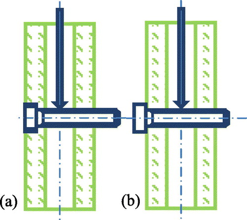
The bone sample was then covered with a black and white speckle pattern for digital image correlation (DIC) measurements. An incremental compressive force of 0-700 N was applied to the sample at a loading velocity of 4 mm/min over four cycles. Two identical cameras (GO-5100M-USB, JAI®), were placed at opposing angles of 10°, 0.8 m from the sample, and were synchronized to film the sample’s screw head area at a frequency of 10 Hz.
2.3 Data analysis
Local sample deformation was calculated using DIC with the image data collected by the cameras. This was carried out using the DIC software named Vic3D (version 7, Correlated Solutions Inc., South Carolina, USA). The pattern and step size were 15 and 5 pixels, respectively; the image pixel size was calculated to be 0.1 mm. An in-house script written in Scilab® v 6.0.2 was used to process the data from the testing machine and from the Vic3D software for all the loading cycles.
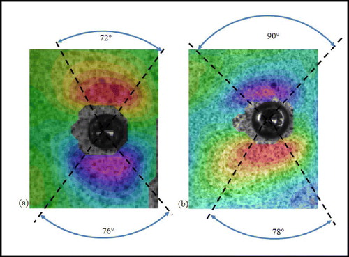
The images corresponding to maximum screw displacement were identified and extracted. A grid of nodal points was applied to the correlated image and the nodes with the maximum positive and negative deformation values were identified. The mean strain was calculated and the zone in which this value ±1 SD could be observed, were recorded as range and angle in a polar coordinate system (). Following an initial analysis of the data, only the longitudinal strain in the loading direction (εyy) appeared as discriminant and used to compare the screw types.
Figure 2. Qualitative strain εyy field for the DTN (a) and ETN (b) screws. Rainbow scale: purple (compression) to red (traction). The dashed lines show the boundaries of mean ±1 SD.
3. Results and discussion
It is of interest to note the differences in strain field between the different screw types. The ETN screw, with a large unthreaded bolt head, generated its highest compression levels proximal to the screw head; whereas the DTN generated its negative deformation levels distal to the screw head ().
This can be explained through the intramedullary test setup which, with the bi-cortical screw insertion, represented a 3-point bending test. The ETN screw head remains external to the cortical layer and loading therefore imitates a 3-pt being test (); whereas the threaded head of the DTN is locked into the cortical layer.
The strain fields are compared in to the accepted levels for bone remodelling provided by Duncan and Turner (Citation1995), which are higher than those proposed by Frost three years earlier. We compare our results with those of Duncan and Turner as composite sawbones represent a strong, healthy bone at less a risk of fracture than a cadaver bone. Both samples transfer the correct level of strain to stimulate normal bone remodelling. Higher mean and maximal compressive strain levels were observed in the DTN sample; neither of the screws provoke excessive deformation. These higher strain levels may be linked to the pre-strain recorded from tightening the screw head into the cortical layer. Negative (i.e., compressive) strain for the ETN is observed over a greater area than for the DTN but provides less mechanical stimulus for bone remodelling.
Table 1. Recorded values in the maximum negative (i.e., compressive) strain zone.
4. Conclusions
The screw head anchorage (threaded or not) seems to affect the deformation patterns transmitted to the cortical bone around the screw head. The consequences on bone remodelling with respect to physiological limits recorded in the literature may be useful to predict the secondary fracture risk in patients post-operation. The results from this study may be of interest to assist the validation of finite element models where cortical surface strains can be compared.
Further tests are planned to assess the strain field pattern for screws type corresponding to the Medial Distal Tibia Plate, a widely used third option for anatomical reduction of distal tibia fractures.
References
- Duncan RL, Turner CH. 1995. Mechanotransduction and the functional response of bone to mechanical strain. Calcif Tissue Int. 57(5):344–358.
- Frost HM. 1992. Perspectives: bone’s mechanical usage windows. Bone Mineral. 19(3):257–271.
- Kuhn S, Appelmann P, Pairon P, Mehler D, Hartmann F, Rommens PL. 2014. A new angle stable nailing concept for the treatment of distal tibia fractures. Int Orthop (Sicot)). 38(6):1255–1260.
- Ruff C, Holt B, Trinkaus E. 2006. Who’s afraid of the big bad Wollf? Am J Phys Anthropol. 129(4):484–498.