
Abstract
This study aimed to investigate the effect of miniscrews thread shape on the stress distribution receiving a torque load. Seven thread shapes (S,V1,V2,B1,B2,R1,R2) models were constructed and a 6 Nmm-torque load was applied. The order of maximum equivalent stress (EQV) value was V1 > V2 > B1 > R1 > R2 > B2 > S. The order of maximum displacement of miniscrew (Max DM) value was S > B2 > R1 = V1 > B1 > V2 > R2. Model R2 may be the most appropriate thread shape affording a torque force.
Introduction
Miniscrew implants have been widely used as orthodontic anchorages due to the benefits of low cost and simple surgical procedure (Chang and Tseng Citation2014). It has been shown that the success rate of miniscrews for orthodontic anchorage ranges from 70% to 90% (Reynders et al. Citation2009). Unlike conventional dental implants needing to wait for osseointegration, miniscrews can be used as orthodontic anchorage immediately after insertion (Lim et al. Citation2009). Primary stability is defined as the implant stability immediately after miniscrew insertion (Wilmes et al. Citation2008), which is mainly dependent on the implant site preparation, bone quality, insertion angle, and miniscrew designs, such as thread length, diameter, thread shape, thread pitch, size of thread ridge (Wilmes et al. Citation2008; Brinley et al. Citation2009; Desai et al. Citation2013; Marquezan et al. Citation2014).
The thread configuration plays an important role in the biomechanical optimization of dental implants (Valen Citation1983; Rieger et al. Citation1990), which should be designed to maximize initial contact, surface area, and facilitate dissipation of stresses at the bone–implant interface (Ivanoff et al. Citation1999). An optimal design of the thread shape is important for sufficient primary stability as orthodontic miniscrews have restrictions in length and diameter (Chang et al. Citation2012). Thread shapes in implant designs include square shape, V-shape, buttress shape, and reverse buttress shape (Motoyoshi et al. Citation2009; Abuhussein et al. Citation2010; Fattahi et al. Citation2015). Several studies have demonstrated that thread shapes can affect stress distribution around the miniscrew (Kim et al. Citation2001; Geng et al. Citation2004; Gracco et al. Citation2012; Fuh et al. Citation2013; Radwan et al. Citation2018; Han et al. Citation2019), which is one of the factors that can affect primary stability of orthodontic miniscrews. However, all these studies investigated the linear force, including vertical forces, oblique load, and axial load. When affording a torque load, the impact of the thread shape on the stress distribution and the micro-movement of the micro-screw are still unknown.
Finite element analysis (FEA) is an efficient technique for evaluating the micromotion of implant (Ma et al. Citation2014) and the stress distribution of bone tissue around miniscrew (Gracco et al. Citation2009; Motoyoshi et al. Citation2009; Eraslan and Inan 2010). FEA has been widely adopted in orthodontic studies (Wakabayashi et al. Citation2008; Kasani et al. Citation2019), such as design of miniscrew (including diameter and length of the miniscrews, thread shape, thread size, degree of taper, and taper length on insertion torque, pullout strength, stiffness) (Chang et al. Citation2012; Duaibis et al. Citation2012; Liu et al. Citation2012).
In the single tooth torque correction (such as uprighting the inclined or tilted molar), using miniscrew as the only orthodontic anchorage is more effective and has a short treatment course as compared with the conventional stainless steel archwire. When serving as the only anchorage of single tooth torque correction, the miniscrew suffers from a torque load. However, no commercial miniscrew is available which is designed specifically for affording the torque load. Moreover, the effect of torque load on the primary stability of micro-implants is largely unknown. We have been working on developing a new type of miniscrew specific for affording the torque load since 2012 (Guo et al. Citation2012; Lu et al. 2013, Citation2014; Lu Y et al. Citation2015). Our previous studies have reported the appropriate length and diameter of the miniscrews affording the torque load (Guo et al. Citation2012; Lu et al. 2013, Citation2014; Lu Y et al. Citation2015). Nevertheless, the appropriate thread shape affording a torque load remains to be investigated. The purpose of this study was to investigate the effect of thread shape on the stress distribution of miniscrews receiving a torque load by FEA.
Materials and methods
Three-dimensional (3D) finite element analysis model
The model of miniscrews and bone blocks was constructed by a commercial FEA software package, which included Mimics 10.1 (Materialise Corporation, Belgian), ANSYS Workbench 13.0 (ANSYS Inc., USA), Unigraphics NX 6.0 (Siemens, Germany), and Geomagic Studio 8.0 (Raindrop Corporation, USA).
The bone block was modeled as a solid cube with 14 mm in height, 7 mm in width, and 10 mm in depth. The block was sectioned into the cortical and cancellous bone layers. The cortical bone layer was one-millimeter thick and was modeled around the cancellous bone. According to our previous series studies (Lu et al. 2013, Citation2014; Lu YJ et al. Citation2015; Lu Y et al. Citation2015), the bone type was set to the type III bone classification of Lekholm and Zarb (Lu et al. 2013).
The miniscrews model was 90 degree positioned inside the bone block. All materials were assumed to be linearly elastic, homogeneous, and isotropic (Dalstra et al. Citation2004; Boccaccio et al. Citation2006) and presented in .
Table 1. The biomechanical parameters of material.
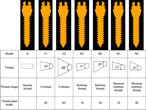
To analyze the impact of thread shape on the primary stability of miniscrew affording a torque force, miniscrew models with 7 different thread shapes were generated: square-thread (S), two truncated V-thread (V1, V2), two buttress thread (B1, B2), and two reverse buttress thread (R1, R2) (). Other variables of thread were kept constant (length = 9 mm, diameter = 2 mm, pitch = 0.6 mm, thread width = 0.2 mm, thread depth= 0.3 mm). The length and diameter were determined according to our previous series studies (Lu et al. 2013, Citation2014; Lu YJ et al. Citation2015; Lu Y et al. Citation2015), while the pitch, thread width, and thread depth was determined based on a previous FEA study (Gracco et al. Citation2009).
Figure 1. The seven models of different thread shapes. Model S, Square thread. Model V1, V-thread with thread apex angle 30°. Model V2, V-thread with thread apex angle 60°. Model B1, buttress thread with thread apex angle 15°. Model B2, buttress thread with thread apex angle 30°. Model R1, reverse buttress thread with thread apex angle 15°. Model R2, reverse buttress thread with thread apex angle 30°.
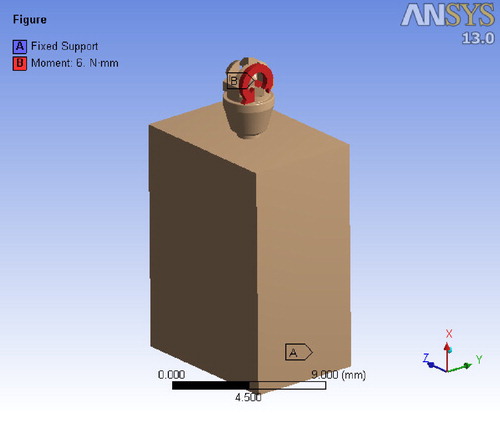
The relationship between miniscrew and the bone model was defined as a contact interaction with finite sliding and the coefficient of friction was 0.3 (Woodall et al. Citation2011). A 6-Nmm torque load was applied in the slot of the top surface of the miniscrew head ().
Figure 2. A 6-Nmm torque load was applied in the slot of the top surface of the miniscrew.
Indicators for biomechanical properties of miniscrew
The maximum equivalent stress (max EQV) is used as an indicator for bone micro-injury (Tada et al. 2003). After the mini-implant is implanted, the lower the Max EQV, the less damage to the surrounding bone tissue, the higher the success rate of implantation (Liu et al. Citation2013). The maximum displacement of miniscrew (Max DM) is used as an indicator for micro-implant mobility. These two indicators (max EQV and Max DM) are commonly used to analyze the biomechanical properties of micro-implants in FEA analysis (Chang et al. Citation2012). All computations were performed on both the 3-D FEA model. Statistical significance analyses were not carried out since the results of FEA are individual values without any statistical spread (Duaibis et al. Citation2012).
Results
Comparison of Max EQV (Mpa) of cortical bone among the miniscrews with different thread shapes
Applying a 6-Nmm torque load (), the equivalent stress distributions of the bone block and the displacement of miniscrew in the 7 models with different thread shapes were analyzed.
The stress distribution in the bone block was shown in . The stress distribution in cortical bone is more concentrated in models S, V1, V2, B1 and R1, while it is more dispersed in models B2 and R2.
Figure 3. The Max EQV in cortical bone in the seven models. The distribution of maximum and strain throughout the bone adjacent to the miniscrew are presented in the form of color band. The red and the blue color indicate the highest and the lowest magnitude of stress.
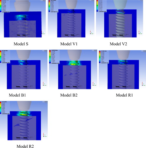
In the model S, B1, R1, the stress was small and centralized. While in the model V1 and V2, the stress was large and centralized. But in the model B2 and R2, the stress was small and dispersed.
The compressive stress in the bone-miniscrew interface was quantitatively determined by the Max EQV (). The red and blue areas represented the maximum and the minimum values of Max EQV, respectively. The values of Max EQV in the 7 models with different thread shapes were summarized in . The Max EQV was markedly higher in the model V1 (38.8 MPa) and V2 (37.61 MPa), and relatively lower in the model S (12.11 MPa), B2 (12.55 MPa) and R2 (12.79 MPa). The order of Max EQV value among the 7 models was V1 > V2 > B1 > R1 > R2 > B2 > S.
Table 2. The maximum displacement of miniscrew and the maximum equivalent stress of cortical bone in the models with different thread shapes.
Comparison of Max DM (µm) of miniscrew of cortical bone among the miniscrews with different thread shapes
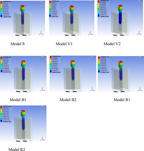
The displacement of miniscrew of the 7 models was demonstrated in , and quantitatively determined by Max DM. As shown in , the Max DM was higher in the model S (3.08 µm) and Model B2 (3.02 µm), and smallest in model R2 (2.71 µm). The order of Max DM value among the 7 models was S > B2 > R1 = V1 > B1 > V2 > R2.
Figure 4. The maximum displacement of miniscrew in the seven models.
Discussion
The V-shape, square shape, buttress shape, and reverse buttress shape are the common thread shapes used in the orthodontic implants (Motoyoshi et al. Citation2009; Abuhussein et al. Citation2010). Several FEA studies have found that under an oblique load, the cervical stress distributes uniformly and both the cervical stress and miniscrew displacement are smallest in V shape thread miniscrew, suggesting that V shape thread is the most appropriate design for the miniscrew affording oblique load (Lan et al. Citation2001; Long et al. Citation2003; Geng et al. Citation2004). Kim et al. have investigated the effects of implants with V thread, square thread and zigzag thread on the implant-bone interface under the axial load by FEA, and revealed that square thread was more appropriate for the implant affording the axial load as it helps to disperse stress distribution in bone-implant interface (Kim et al. Citation2001). Although these studies suggest the most appropriate thread shapes for the miniscrews affording linear force (including vertical forces, oblique load, or axial load), the appropriate thread shape for the miniscrew affording a torque load remains to be investigated.
When serving as the only anchorage of single tooth torque correction, the miniscrew affords a torque load. We have been working on developing the miniscrew specific for affording the torque load (Guo et al. Citation2012; Lu et al. 2013, Citation2014). In this study, we investigated the effect of thread shape on the stress distribution of miniscrews with different thread shapes receiving a torque load by FEA. Hohmann et al. demonstrate that the torque load exceeding 6 Nmm would induce molar root resorption (Hohmann et al. Citation2007), therefore, the torque force on the molar should not exceed 6 Nmm. If the miniscrew applies a torque of 6 Nmm to the molar, the miniscrew also receives a torque of 6 Nmm. As a result, the torque load of 6 Nmm was applied in our FEA model. The miniscrew stability is supported by the mechanical interaction between miniscrew and the cortical bone (Lim et al. Citation2009) and was evaluated by the maximum equivalent stress of cortical bone and the maximum displacement of miniscrew. Our results showed that the stress in the cortical bone mainly distributed on the compression side in the model S, V1, V2, B1, and R1, while distributed more dispersedly in the model B2 and R2. In addition, the stress was small and dispersed in the model B2 and R2, small and centralized in the model S, B1, R1, but large and centralized in the model V1 and V2. The order of Max DM value among the 7 models was S > B2 > R1 = V1 > B1 > V2 > R2. These data indicated that when a 6-Nmm torque force was applied in the seven models in our study, the compressive stress in the bone-miniscrew interface was relatively small in the model B2 and R2. The Max DM value reflects the micromotion at the bone-implant interface (Lee et al. Citation2017). Our FEA results demonstrated that the Max DM value was relatively higher in the model S and Model B2, but smallest in the model R2. The order of Max DM value among the 7 models was S > B2 > R1 = V1 > B1 > V2 > R2. Comprehensively considering the results of the stress distribution, the maximum equivalent stress of cortical bone and the maximum displacement of miniscrew, it was suggested that the model R2 is the most appropriate thread shape among the 7 models for the miniscrew affording a torque force. To our best knowledge, this is the first study reporting the appropriate thread shape for the miniscrew affording a torque force.
Several limitations of this study should be pointed out. First, we only applied a torque load of 6 Nmm for the FEA model. Other torque loads smaller than 6 Nmm should also be tested in the modeling. In addition, other parameters of miniscrews, such as the length and diameter of miniscrew, thread pitch, thread width, and thread depth could be also changed in the modeling. Furthermore, the findings of FEA model should be validated in the in vitro pull-out test or in an in vivo animal model to further determine the effect of the thread shape on the micromotion of miniscrew with a torque force. All these limitations should be addressed in the following studies.
In summary, our results suggested that when affording a torque force of 6 Nmm, the model R2 had the smallest maximum displacement of miniscrew and relatively lower maximum equivalent stress in the bone-miniscrew interface, which may be the most appropriate thread shape among the 7 test models for the miniscrew affording a torque force. Our findings are helpful for designing the miniscrews specific for affording the torque load.
Acknowledgment
The authors gratefully acknowledge the professor Zhang jinxin from School of public health of SUN YAT-SEN University for his assistance in reviewing the statistical analyses of the data.
Disclosure statement
No potential conflict of interest was reported by the authors.
Additional information
Funding
References
- Abuhussein H, Pagni G, Rebaudi A, Wang HL. 2010. The effect of thread pattern upon implant osseointegration: review. Clin Oral Implants Res. 21(2):129–136.
- Boccaccio A, Lamberti L, Pappalettere C, Carano A, Cozzani M. 2006. Mechanical behavior of an osteotomized mandible with distraction orthodontic devices. J Biomech. 39(15):2907–2918.
- Brinley CL, Behrents R, Kim KB, Sridhar C, Kyung HM, Buschang PH. 2009. Pitch and longitudinal fluting effects on the primary stability of miniscrew implants. Angle Orthod. 79(6):1156–1161.
- Chang HP, Tseng YC. 2014. Miniscrew implant applications in contemporary orthodontics. Kaohsiung J Med Sci. 30(3):111–115.
- Chang JZC, Chen YJ, Tung YY, Chiang YY, Lai EHH, Chen WP, Lin CP. 2012. Effects of thread depth, taper shape, and taper length on the mechanical properties of mini-implants. Am J Orthod Dentofac Orthop. 141(3):279–288.
- Dalstra M, Cattaneo P, Melsen B. 2004. Load transfer of miniscrews for orthodontic anchorage. Orthodontics. 1:53–62.
- Desai S, Singh R, Karthikeyan I. 2013. 2D FEA of evaluation of micromovements and stresses at bone-implant interface in immediately loaded tapered implants in the posterior maxilla. J Indian Soc Periodontol. 17(5):637–643.
- Duaibis R, Kusnoto B, Natarajan R, Zhao L, Evans C. 2012. Factors affecting stresses in cortical bone around miniscrew implants: a three-dimensional finite element study. Angle Orthod. 82:875–880.
- Eraslan O, Inan O. 2010. The effect of thread design on stress distribution in a solid screw implant: a 3D finite element analysis. Clin Oral Invest. 14(4):411–416.
- Fattahi H, Ajami S, NabavizadehRafsanjani A. 2015. The effects of different miniscrew thread designs and force directions on stress distribution by 3-dimensional finite element analysis. J Dent (Shiraz). 16(4):341–348. Iran).
- Fuh L-J, Hsu J-T, Huang H-L, Chen MY, Shen Y-W. 2013. Biomechanical investigation of thread designs and interface conditions of zirconia and titanium dental implants with bone: three-dimensional numeric analysis. Int J Oral Maxillofac Implants. 28(2):e64–e71.
- Geng JP, Ma QS, Xu W, Tan KBC, Liu GR. 2004. Finite element analysis of four thread-form configurations in a stepped screw implant. J Oral Rehabil. 31(3):233–239.
- Gracco A, Cirignaco A, Cozzani M, Boccaccio A, Pappalettere C, Vitale G. 2009. Numerical/experimental analysis of the stress field around miniscrews for orthodontic anchorage. Eur J Orthod. 31(1):12–20.
- Gracco A, Giagnorio C, Incerti Parenti S, Alessandri Bonetti G, Siciliani G. 2012. Effects of thread shape on the pullout strength of miniscrews. Am J Orthod Dentofac Orthop. 142(2):186–190.
- Guo D, Chang S, Hu L, Lu Y, Ye Y. 2012. Biomechanics of upper molar uprighting with Tomas microimplant: a finite element study. Chin J Orthod. 19:86–91.
- Han CM, Watanabe K, Tsatalis AE, Lee D, Zheng F, Kyung HM, Deguchi T, Kim DG. 2019. Evaluations of miniscrew type-dependent mechanical stability. Clin Biomech. 69:21–27.
- Hohmann A, Wolfram U, Geiger M, Boryor A, Sander C, Faltin R, Faltin K, Sander FG. 2007. Periodontal ligament hydrostatic pressure with areas of root resorption after application of a continuous torque moment. Angle Orthod. 77(4):653–659.
- Ivanoff CJ, Gröndahl K, Sennerby L, Bergström C, Lekholm U. 1999. Influence of variations in implant diameters: a 3- to 5-year retrospective clinical report. Int J Oral Maxillofac Implants. 14(2):173–180.
- Kasani R, Rama Sai Attili BK, Dommeti VK, Merdji A, Biswas JK, Roy S. 2019. Stress distribution of overdenture using odd number implants – a finite element study. J Mech Behav Biomed Mater. 98:369–382.
- Kim W, Cha Y, Oh S. 2001. The three dimensional finite element analysis of stress according to implant thread design under the axial load. J Korean Assoc Oral Maxillofac Surg. 27:3–8.
- Lan Z, Lin Z, Li N. 2001. The effects of implant morphology on stress distribution in implant-bone interface. J Pr Stomatol. 7:246–248.
- Lee J, Jeong YH, Pittman J, Deguchi T, Johnston WM, Fields HW, Kim DG. 2017. Primary stability and viscoelastic displacement of mini-implant system under loading. Clin Biomech (Bristol, Avon). 41:28–33.
- Lim HJ, Eun CS, Cho JH, Lee KH, Hwang HS. 2009. Factors associated with initial stability of miniscrews for orthodontic treatment. Am J Orthod Dentofac Orthop. 136(2):236–242.
- Liu J, Pan S, Dong J, Mo Z, Fan Y, Feng H. 2013. Influence of implant number on the biomechanical behaviour of mandibular implant-retained/supported overdentures: A three-dimensional finite element analysis. J Dent. 41(3):241–249.
- Liu TC, Chang CH, Wong TY, Liu JK. 2012. Finite element analysis of miniscrew implants used for orthodontic anchorage. Am J Orthod Dentofac Orthop. 141(4):468–476.
- Long H, Lin Z, Lan Z, Zhou L. 2003. The effects of implant shapes on stress distribution in implant-bone interface. Chin J Oral Implantol. 8:61–63.
- Lu Y, Chang S, Wu H, Yu YYY. 2013. Influence of the diameter and length of the mini-implant on the primary stability after loading with composite forces. Zhonghua Kou Qiang Yi Xue Za Zhi. 48:37–40. [].
- Lu Y, Chang S, Wu H, Yu Y, Ye Y, Chang L, Wang W. 2014. Selection of optimal length and diameter of mini implant in two different forces: a three-dimensional finite element analysis. Hua Xi Kou Qiang Yi Xue Za Zhi. 32(1):85–90.
- Lu Y, Chang S, Ye J, Ye Y, Yu Y. 2015. Analysis on the stress of the bone surrounding mini-implant with different diameters and lengths under torque. BME. 26(s1):S541–S545.
- Lu YJ, Chang SH, Ye JT, Ye YS, Yu YS. 2015. Finite Element Analysis of Bone Stress around Micro-Implants of Different Diameters and Lengths with Application of a Single or Composite Torque Force. PLoS One. 10(12):e0144744.
- Ma P, Xiong W, Tan B, Geng W, Liu J, Li W, Li D. 2014. Influence of thread pitch, helix angle, and compactness on micromotion of immediately loaded implants in three types of bone quality: A three-dimensional finite element analysis. Biomed Res Int. 2014(:983103
- Marquezan M, Mattos CT, Sant'Anna EF, de Souza MMG, Maia LC. 2014. Does cortical thickness influence the primary stability of miniscrews?: A systematic review and meta-analysis. Angle Orthod. 84(6):1093–1103.
- Motoyoshi M, Inaba M, Ueno S, Shimizu N. 2009. Mechanical anisotropy of orthodontic mini-implants. Int J Oral Maxillofac Surg. 38(9):972–977.
- Radwan ES, Montasser MA, Maher A. 2018. Influence of geometric design characteristics on primary stability of orthodontic miniscrews. J Orofac Orthop. 79(3):191–203.
- Reynders R, Ronchi L, Bipat S. 2009. Mini-implants in orthodontics: A systematic review of the literature. Am J Orthod Dentofac Orthop. 135(5):564.e1
- Rieger MR, Adams WK, Kinzel GL. 1990. A finite element survey of eleven endosseous implants. J Prosthet Dent. 63(4):457–465.
- Tada S, Stegaroiu R, Kitamura E, Miyakawa O, Kusakari H. 2003 May-Jun. Influence of implant design and bone quality on stress/strain distribution in bone around implants: a 3-dimensional finite element analysis. Int J Oral Maxillofac Implants. 18(3):357–368.
- Valen M. 1983. The relationship between endosteal implant design and function: maximum stress distribution with computer-formed, three dimensional Flexi-Cup blades. J Oral Implantol. 11(1):49–71.
- Wakabayashi N, Ona M, Suzuki T, Igarashi Y. 2008. Nonlinear finite element analyses: Advances and challenges in dental applications. J Dent. 36(7):463–471.
- Wilmes B, Ottenstreuer S, Su Y-Y, Drescher D. 2008. Impact of implant design on primary stability of orthodontic mini-implants. J Orofac Orthop. 69(1):42–50.
- Woodall N, Tadepalli SC, Qian F, Grosland NM, Marshall SD, Southard TE. 2011. Effect of miniscrew angulation on anchorage resistance. Am J Orthod Dentofac Orthop. 139(2):e147–152.