
1. Introduction
Prosthetic sockets aim at coupling the residual limb to the prosthesis and at transmitting the body load while walking. Properly fitted sockets allow their users controlling optimally their prosthesis and preventing the effects of pressure and shear from causing them pain and injuries. During rehabilitation, estimating these efforts could prove useful for adequate socket fitting. Various means were proposed to measure these forces (Al-Fakih et al. Citation2016), but had drawbacks: limited to pressure measurement, to specific points, alteration of the socket or the stump/socket contact, limited to finite element analysis (Lee Winson et al. Citation2004). Another approach consists in estimating the internal pressure by measuring the socket deformation with strain gauges placed in its external part (Sewell et al. Citation2012) without altering the structure, composition or materials used in the prosthesis itself, that is, non-invasively. However, measuring 3 D efforts required increasing the number of gauges. But the cost of commercial systems allowing the synchronized measurement of multiple resistive sensors is often high. In this study, an innovative low-cost system was proposed to assess the internal 3 D forces of a socket without affecting its structure or functionality using strain gauges located on its external surface, calibrated by means of artificial neural networks (ANN), and primary validation was conducted.
2. Methods
2.1. Acquisition and calibration material
Acquisition: One transtibial socket was used and divided into 10 regions, drawn on its external surface. 35 strain gauges were attached and distributed all over the sockets external surface. Synchronized acquisitions of strain gauge signals were achieved using a custom system card-based Arduino MEGA 2560 and 35 Analog-Digital Converter modules (HX711) to read the gauges signals (16 Hz).
Calibration: The instrumented socket was docked on a 3 D force sensor (FN7325-M6, Sensor solutions), which was fixed onto a system allowing translation in horizontal plane and rotation around the vertical axis. A vertical bar inserted in the socket from the top, with vertical adjustment structure, allowed pressure and shear forces to be applied manually from the inside and to the socket, allowing its vertical displacement (). The bar has a spherical tip coated with an anti-slip plastic material that emulated the effect of the skin/liner on the socket. The 3 D sensor was calibrated, conditioned, and paired with the acquisition system via NI LabView NXG 3.0 software (1000 Hz).
Figure 1. Assembly of the lower limb socket on the calibration system.
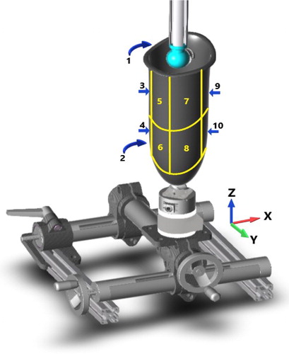
Socket geometry: The socket and the sensor geometries were acquired using a 3 D scanner (Einscan pro, Shining 3 D), enabling to define the key-geometric features: sensor center (origin), plane frames of 10 regions over the socket.
2.2. Data acquisition: calibration and validation
System calibration was performed by stressing the center of each region of the socket through the sphere. Signals of the 35 strain gauges were simultaneously recorded with the applied force measured though the 3 D sensor. For this, the following measurement protocol was applied for each region:
The sphere is placed, without contact, in front of the region center, and the acquisition is then launched.
An increasing force is manually imposed on the socket, by translating it towards the sphere through an endless screw system at an average increasing force of 50 N per second, up to a maximum.
Shear forces in both directions are imposed, using the vertical and horizontal translation systems, up to the maximum possible without slipping.
The non-contact is restored at the end.
2.3. Data processing
Gauge data was declared as entry matrix of the ANN.
Effort data: The efforts recorded by the sensor were expressed in the region coordinates system with normal (Z) and shear (X, Y) directions. The ANN output matrix that contains effort data relative to ten regions was created, where registered efforts were placed in the columns corresponding to the X, Y, Z force components of the region in contact with the sphere, and zeros were placed in the other columns to fill the non-contact condition. Effort and strain gauge data were synchronized, so that each gauge acquisition line corresponded to an effort data line.
Calibration and validation data selection: one third of the acquisition was randomly affected to data validation, the rest was affected to data calibration.
Calibration data cleaning: Data redundancy in efforts was deleted, in order to obtain equally distributed points in the X, Y, Z effort space, as it might cause an overtraining of the ANN. A hundred effort data points per region were selected, covering the range of efforts imposed to each of the 10 regions. The corresponding lines of the gauge data were selected, leading to 1000 training data.
Neural network training: a neural network, with 35 entries corresponding to the gauge signals, 30 entries corresponding to the X, Y and Z efforts on each of the 10 regions, and with a hidden layer of 30 neurons was trained with the 1000 training data.
3. Results and discussion
Maximum normal efforts ranged from 310 to 721 N, depending on the region, and maximum shear efforts ranged from 141 to 688 N, which was comparable to efforts observed for transtibial amputees during gait (Sewell et al. Citation2012). Mean absolute differences observed between computed and measured forces ranged from 5 to 58 N, whereas normalized RMS error were inferior to 17% in the tightest internal posterior regions, by contrast regions 1, 7, 8 and 10 were between 21% to 32% of the maximum stress (). The system was then considered promising at this stage of development, to estimate the 3 D efforts inside the socket, without altering the stump/socket contact, and with an affordable cost estimated at 2000 €.
The present system requires further upgrades, like creating one ANN per region gain precision, increasing the sample rate, selecting the adequate number of gauges, or estimating the efforts on other points. The system also needs to be field proven by comparing its results to direct measurements in real situation.
Table 1. Normalized RMS error per axis and region, percentage of the effort range.
4. Conclusions
Evidence from the tests showed promising results in estimating the efforts applied inside the socket by using the data obtained from the gauges, without altering the socket or the stump/socket contact. Further research will focus on validation, by applying efforts in other points than the center of the region, also applying multiple contact points and testing on an artificial instrumented stump. Then measurement on real patient could be conducted in various situations static standing, level walking, stand up, stairs, etc. The information provided could be useful when fitting a prosthesis or understanding the effect of its shape or patient volume change on pain and discomfort. The autonomy of the system and its portability will allow to the prosthetic user to be instrumented in environmental situation and could evolve towards clinical compatible tool.
Additional information
Funding
References
- Al-Fakih EA, Abu Osman NA, Mahmad Adikan FR. 2016. Techniques for interface stress measurements within prosthetic sockets of transtibial amputees: a review of the past 50 years of research. Sensors. 16(7):1119.
- Lee Winson CC, Zhang M, Boone DA, Contoyannis B. 2004. Finite-element analysis to determine effect of monolimb flexibility on structural strength and interaction between residual limb and prosthetic socket. J Rehabil Res Dev. 41(6A):775– 786.
- Sewell P, Noroozi S, Vinney J, Amali R, Andrew S. 2012. Static and dynamic pressure prediction for prosthetic socket fitting assessment utilising an inverse problem approach. Artif Intell Med. 54(1):29–41.