
1. Introduction
During every machining operation, a part of the energy necessary to cut dispels into heat. Heat is associated with the plastic deformation in the different shear zones (even for bone tissues; Liao and Axinte Citation2016), and with the frictional dissipation energy generated at the tool-chip interface and at the interface between tool and sample. During surgery, bone drilling leads therefore to an increase of temperature that can potentially cause osteonecrosis, if the level of temperature and/or the duration of exposition is too high. The recent work of Feldmann et al (Citation2018) showed that the heat conductivity of bone tissues is highly dependent on the bone volume fraction. As this volume fraction is varying locally inside bone tissues, a systematic experimental campaign allowing to identify the heat sources during drilling is hard to conduct. To counter this difficulty, a homogeneous and porosity-controlled material is used in the present experimental work to identify the causes of the thermal loading into the sample. The results of the experiments will allow to improve the analytical model previously developed (Amewoui et al. Citation2019) for predicting the temperature during bone drilling.
2. Methods
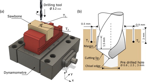
Following the previous work of Cseke and Heinemann (Citation2018) and with adequacy to ASTM F-1839-08, the Sawbones porous biomedical test material PU50 (ref 1522-27) whose apparent density is 0.8 g/cm3 was chosen. Drilling experiments were conducted on a CNC milling machine Roeders RXP200DS. The drilling depth was fixed to 4 mm. Samples were clamped and mounted on a Kistler 9256C2 piezoelectric dynamometer to measure the feed force Fz and the cutting torque Mz, see . The signal was amplified by a Kistler 5017B charge amplifier and recorded by a National Instrument data acquisition system coupled with a Labview software. Temperature data were recorded by two K-type thermocouples with a wire diameter of 0.25 mm implanted in the sample. Following the preparation of the holes, the measuring junctions were positioned precisely at 2 mm depth and 0.5 (thermocouple T1) and 0.9 mm (thermocouple T2) from the drilled hole wall. A Nobel Biocare twist drill dedicated to hole preparation before implant insertion is used. The 3.2 mm diameter drill is characterized by a point angle of 118°, a helix angle of 30° To reduce friction between the tool margin and borehole wall, the diameter is left intact at 1.5 mm and is reducing after, see .
Figure 1. Experimental setup.
To analyze the effect of the principal cutting edge and tool margin on forces and temperatures, predrilled holes of 0.8, 2.5, 3 and 3.2 mm were previously prepared to progressively annihilate the cut of the principal drill cutting edge. It also allows to simulate the multistepped surgical procedure adopted for example in dental surgery and consisting in increasing progressively the diameter of the drilled hole.
Cutting speed of 64 m/min and a feed of 0.04 mm/rev were selected for this study.
3. Results and discussion
3.1. Effect on cutting forces
The values of thrust forces and torques measured are reported in . The thrust force decreases when the diameter of the predrilled hole is increasing. This trend can be partly explained by the geometry of the drill. Indeed, the principal cutting edge (cone area) is divided into two major zones: chisel edge and cutting lip. The kinematics of the drilling process involves varying continuously the cutting speed along the cutting edges of the drill, from zero at the drill tip to a maximum value at the periphery. It results in a significant penetration force Fz in the central part of the drilled area, due more to an indentation process than to a true cutting operation. With the drilling of starter holes, the indentation phenomenon is canceled and the thrust force linearly decreases with the increase of the predrilled hole diameter. A value of zero is reached with a 3.2 mm diameter predrilled hole. On the contrary, the torque value is comparable with a predrilled hole of 0.8 and 2.5 mm in diameter which indicates that the influence of the center of the tool is negligible on torque. With a higher predrilled hole of 3 mm, torque is reduced by 30%. At last, after a predrilling of 3.2 mm, a torque value still appears, representing around 25% of the initial torque. This value can be considered as a rubbing effect of the radial tool margin on the borehole wall, the cut being inexistent.
Table 1. Influence of pre-drill hole diameter on thrust force, torque and temperature measured by thermocouple T1 and T2.
3.2. Effect on temperature
Temperature from thermocouple T1 decreases gradually to a value near 10 °C when the diameter of the predrilled hole reaches 3.2 mm. This remaining temperature elevation is the result of the heat generated only by lateral friction between hole and tool. However, the temperature resulting from cutting and rubbing, on the principal cutting edge, is not negligible; the difference of measured temperature being of 15 °C when cutting with or without a predrilled hole of 3.2 mm diameter.
Moreover, because of the thermal conductivity of the sawbones sample and the feed rate of the tool, the distance between the thermocouples, even T1, and the center of the tool is too high to identify the thermal contribution of the indentation area of the chisel edge.
For thermocouple T2, the temperature variation is less effective, confirming the influence of the location of the measurement meaning on the conclusions.
These experiments provide useful information about the contribution of the various heat sources to the global temperature elevation. However, to obtain a complete and more detailed mapping of the temperature into the sample, an inverse model is still necessary. These experimental investigations will help to optimize the calibration of previous analytical models (Amewoui et al. Citation2019) but also confirm the necessity to integrate the geometry of the tool inside the model.
4. Conclusions
Experimental tests have been conducted on a controlled porosity material mimicking bone in order to identify the heat sources leading to temperature elevation during drilling. This study with predrill holes at various diameters confirms the influence of lateral friction on torque, leading to temperature elevation. However, the main contribution of cutting forces and temperatures measured results from the principal cutting edge. The study proposes to discretize the principal cutting edge to isolate the force and thermal effect of the separate elements, giving information to potential analytical models. Indeed, thermocouple only measures temperature at a single point, relatively far from heating. An inverse method must be applied to obtain the temperature close to the drilled hole wall, where necrosis risks are the most important, requiring further investigations.
References
- Amewoui F, Le Coz G ,Bonnet, AS, Moufki A. 2019. Bone drilling: a thermal model for bone temperature prediction. Comput Meth. Biomech Biomed Eng. 22(sup1):S1–S393.
- Cseke A, Heinemann R. 2018. The effects of cutting parameters on cutting forces and heat generation when drilling animal bone and biomechanical test materials. Med Eng Phys. 51:24–30.
- Feldmann A, Wili P, Maquer G, Zysset P. 2018. The thermal conductivity of cortical and cancellous bone. Eur Cell Mater. 35(35):25–33.
- Liao Z, Axinte DA. 2016. On chip formation mechanism in orthogonal cutting of bone. Int. J. Mach Tool Manu. 102:41–55.