
1. Introduction
Cells are biomechanical entities that exert and respond to mechanical forces in addition to biochemical signals. Both types of signals co-regulate processes such as cell differentiation, movement, division… The present model is a stepping stone towards the development of a multicellular model built to represent the formation of new blood vessels, a process known as angiogenesis. Interestingly, during new vessel formation, cells rely on several mechanical cues that influence their behaviour and morphology (Merks et al. Citation2006), those include the rigidity gradients of the substrate or the forces generated by the cells. As a consequence, the cell model must include relevant mechanical features involved in cell migration and be designed to allow cells to interact with other cells, so as to enable emergent behaviours such as the ones observed during angiogenesis. This means that our cell model will be developed as an autonomous migrating agent based on mechanical principles.
After analysing the literature, we see that agent-based models are lattice based (Boas et al. Citation2018), point based (where the cell is modelled as a point) (Stefanoni et al. Citation2011) or computationally costly and complicated making them impractical to implement in simulations involving high cell numbers.
Here a discrete cellular model is proposed as a first step, to study cell migration on a 2 D environment, including minimal biomechanical ingredients for further developments.
2. Methods
2.1. Protrusions
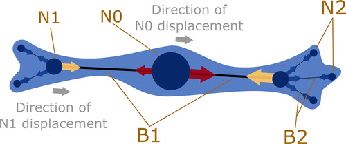
The 2D cell is modelled by a central node (N0), which can be thought of as the centre of the cell. From there, the cell is able to form protrusions. Each protrusion that is connected to N0 is composed of a child branch (B1) and a child node (N1) (see ). A protrusion is intended to either represent a filopodium (not used in this study), lamellipodium or a cortex protrusion.
Figure 1. Schematic representation of the cell model.
To test the model’s ability to reproduce random cell movement, it is assumed here that protrusions are randomly created. Protrusions are created as lamellipodia, with length distributed in a random manner. Lamellipodia protrusions can mature into cortex protrusions.
N0: central node, N1 child node of N0, N2 child node of N1. B1: Branch connecting N0 to N1. B2: Branch connecting N1 to N2. Red, yellow and blue arrows show forces applied on each node due to elasticity and actomyosin contractility. Yellow arrows represent forces applied on N1 by the contractility and elasticity of their respective B1. Red arrows are the forces applied on the N0 by each B1. The resulting force imbalance leads to movement of the corresponding node, as represented by grey arrows. The cell body is drawn for illustrative purposes only (light blue).
The cortex protrusion is contractile and also includes substrate dependent stress fibre contractility and mature adhesions that bind the cell to the substrate. Both cortical and stress fibre contractility are modelled by opposite forces, respectively applied on the parent and child nodes (see ), meant to bring both nodes closer. The motor force representing acto-myosin contractility is applied on each node, but if the nodes are being pulled apart by external forces, then the restoring force is modelled as linearly elastic (passive spring).
To better fit observed complex cellular shapes, we allow protrusions that are directly connected to the central node to form their own secondary protrusions. The latter includes a branch (B2) connecting the parent node (N1) to its child node (N2) (see ).
The cell movement is achieved by the collective interaction between all of the protrusions. Lamellipodia expand the reach of the cell and then mature into a contractile protrusion that pulls together, from both ends, on the rest of the cell.
When two nodes are too close, they merge. The parent node absorbs its child node and inherits the protrusions associated to it. This is how protrusions disappear.
This process is largely dependent on the adhesion conditions of each node.
2.2. Adhesions
In our model a node can either be bound or unbound. If bound, a no-slip condition is applied on the node. The no-slip condition is limited both by a half-life and a rupture force. A bound node is thus equivalent to a focal adhesion and other types of adhesions that prevent local relative movements between the cell and its substrate. The half-life attributed to a node represents a simplified non deterministic description of bondage during random cell migration. When a bound adhesion “dies” it becomes unbound.
When an adhesion is unbound, the node slips on the substrate with a viscous drag force.
2.3. Mechanics
Contractility forces are calculated using values found in the literature (Ghibaudo et al. Citation2008). Forces are applied on nodes (see ) to determine their displacement, which are calculated using an explicit quasi-static mechanical solving method for fixed time step intervals.
2.4. Simulations
The model is coded using C++ and object-oriented paradigms. The model ran for 50 simulations of a single cell subject to random walk during 2 hours on a 2D substrate with a Young’s modulus of 20 kPa.
3. Results and discussion
In this study, numerically obtained cell shapes were in part restricted by the probability distribution of protrusion lengths at creation, and by a regulated number of protrusions per parent node. In addition node half-life unbaled nodes to move and merge. Yet, cells were free to adopt a wide range of shapes that all lead to random migration (see ).
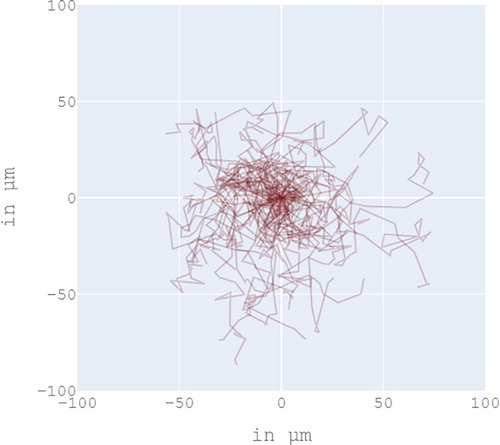
Figure 2. Random cell migration.
Here protrusion creation (assumed random), adhesion dynamics (simply controlled by half-life expectation and a rupture force) and mechanical forces were defined using minimal elements to successfully produce random cell movements driven by mechanical principles. Interestingly, these three elements can easily be adapted to model various oriented migration types and include various mechanical aspects such as chemo and mechanotaxis (Nicolas et al. Citation2004).
Each path drawn in red represents the trajectory of a single cell subject to random walk for 2 hours, with initial cell position centred at (0, 0). The graph is an overlay of 50 single cell simulations. Total computation time took about 1 hour.
4. Conclusions
The agent-based cell model presented here is relatively simple, faster than real time and lightweight meaning that many cells can be included in the same simulation. Moreover the model is easily adaptable to 3D.
Additional information
Funding
References
- Boas SEM, Jiang Y, Merks RMH, Prokopiou SA, Rens EG. 2018. Cellular Potts model: applications to vasculogenesis and angiogenesis. In: Louis P-Y, Nardi FR, editors. Probabilistic cellular automata [Internet]. Vol. 27. Cham: Springer International Publishing; [accessed 2019 Oct 21]; p. 279–310.
- Ghibaudo M, Saez A, Trichet L, Xayaphoummine A, Browaeys J, Silberzan P, Buguin A, Ladoux B. 2008. Traction forces and rigidity sensing regulate cell functions. Soft Matter. 4(9):1836–1843.
- Merks RMH, Brodsky SV, Goligorksy MS, Newman SA, Glazier JA. 2006. Cell elongation is key to in silico replication of in vitro vasculogenesis and subsequent remodeling. Dev Biol. 289(1):44–54.
- Nicolas A, Geiger B, Safran SA. 2004. Cell mechanosensitivity controls the anisotropy of focal adhesions. Proc National Acad Sci. 101(34):12520–12525.
- Stefanoni F, Ventre M, Mollica F, Netti PA. 2011. A numerical model for durotaxis. J Theor Biol. 280(1):150–158.