
 ?Mathematical formulae have been encoded as MathML and are displayed in this HTML version using MathJax in order to improve their display. Uncheck the box to turn MathJax off. This feature requires Javascript. Click on a formula to zoom.
1. Introduction
Wearable sensor makes possible today to obtain motion measurement for health monitoring, physical activity assessment, or sport performance evaluation in ecological environment. One of them, the inertial measurement unit (IMU), is extensively used to obtain measurements relative to human motion. The IMU, composed of 3D gyroscope, accelerometer, and generally magnetometer, can be used to provide an orientation in a global coordinate system after fusion of the different sensor data.
The principal issue to obtain the human movement measurement is the sensor-to-segment (S2S) calibration, which provides the orientation of the IMU relatively to the segment on which it is fixed (Picerno Citation2017). This calibration aims to define the localization of the segment axes in the IMUs technical coordinate system. Different approaches have been made in the literature to perform this calibration. Static calibration defines segment axes during specific static postures by making assumptions regarding the alignment of the axes relatively to the vertical (Palermo et al. Citation2014). Functional calibration hypothesises that the subject can perfectly rotate around segment axes during specific movements (Favre et al. Citation2008). Anatomical calibration uses a supplementary device to locate the segment axes in the IMU coordinate system (Picerno et al. Citation2008).
Today, there is no consensus on which calibration method is the most appropriate to perform S2S calibration. The aim of this study is then to compare different S2S calibration methods for lower limb segments. In the present study, the segment axes are defined during different movements and postures deduced from markers tracked with optoelectronic system, not by IMU measurement, in order to distinguish errors due to the measurement system from errors due to the calibration method by itself. The axes, thus, obtained are compared with axes obtained with a method of reference proposed for optoelectronic measurement. This method of reference is based on recommendations formulated by the ISB (Wu et al. Citation2002) and on the recommendations the most recently formulated in the literature (Kainz et al. Citation2017). The difference in segment axes orientation will then be exclusively due to the axe definition method.
2. Methods
Ten asymptomatic subjects, five males and five females, participated to this study. Nineteen optoelectronic cameras (Vicon, Oxford, UK) were used to track 28 markers trajectory at a frequency of 150 Hz. The Conventional Gait Model marker set version 2.3 was used.
The method of reference used to define the hip joint centre is a functional method (Halvorsen Citation2003), as well as for the knee and the ankle medio-lateral axes (Ehrig et al. Citation2007). The movements used are the combination of those in . The reference segments coordinate system are defined according to the ISB recommendation.
Table 1. Segment axes (medio-lateral, antero-posterior, longitudinal) deduced from the different S2S calibration methods.
Technical coordinate systems are defined by using, from the marker set, the markers the less sensitive to the soft tissue artefact. The orientations of these technical coordinate systems in the global coordinate system are then expressed in quaternions to imitate IMU output data.
presents the different postures and movements tested to obtain the segments axes. For the static method, during upright posture, the segments longitudinal axes are supposed to be aligned with the vertical and then computed as the mean vertical axis expressed in the technical coordinated system.
For the pelvis axes, a device is used, inspired by Picerno et al. (Citation2008) anatomical approach. The device is composed of a rigid frame and four rigid spikes used to point the four superior iliac spines. The segment axes are then obtained by defining vectors based on markers positioned on the device.
Regarding the functional movements, the segment axes are computed as the mean unit axis of the quaternion defining the segment orientation relatively to its proximal segment.
The error of the S2S calibration is assessed by computing during the static upright posture the absolute angle existing between the axis obtained with the S2S calibration
method and the axis obtained with the method of reference
.
To compare the error obtained for each S2S calibration method, a Friedman test is run as well as Wilcoxon post hoc test if required.
3. Results and discussion
In , only cases with significant error differences according to the Friedman test are displayed. The differences are then significant for pelvis, femur, and tibia ML axes as well as for pelvis and femur L axes. No significant difference is found for AP, tibia L, and foot axes.
Figure 1. Significant error in segment axes definition, P means Passive movement, *p < .05, **p < .01.
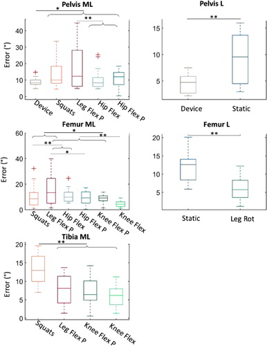
According to the post hoc tests represented on , the pelvis ML and L axes are well defined by the device with a mean error of 8.9° and 4.7°. The smallest errors for femur and tibia ML axes are obtained with active knee flexions, with a mean error of 4.5° and 5.9°, respectively. The L axis of femur has a mean error of 5.9° with leg rotation.
A static position, the use of the device, knee flexions, and leg rotations is the best combination to obtain all the lower-body axes with a minimum of error. However, such a combination could be difficult to apply in clinical settings due to patients’ limited range of motion or poor movement selectivity but also because of the time required for the whole protocol.
4. Conclusions
This study compares different proposals for lower-limb S2S calibration with inertial sensors. A combination including a static position, the use of the device, knee flexions, and leg rotations is the best to obtain all the lower-body segment axes with a minimum of error. However, repeatability of the postures, movements, and device use must be further investigated to validate the robustness of the proposal.
References
- Ehrig RM, Taylor WR, Duda GN, Heller MO. 2007. A survey of formal methods for determining functional joint axes. J Biomech. 40(10):2150–2157.
- Favre J, Jolles BMM, Aissaoui R, Aminian K. 2008. Ambulatory measurement of 3D knee joint angle. J Biomech. 41(5):1029–1035.
- Halvorsen K. 2003. Bias compensated least squares estimate of the center of rotation. J Biomech. 36(7):999–1008.
- Kainz H, Hajek M, Modenese L, Saxby DJ, Lloyd DG, Carty CP. 2017. Reliability of functional and predictive methods to estimate the hip joint centre in human motion analysis in healthy adults. Gait Posture. 53:179–184.
- Palermo E, Rossi S, Marini F, Patanè F, Cappa P. 2014. Experimental evaluation of accuracy and repeatability of a novel body-to-sensor calibration procedure for inertial sensor-based gait analysis. Measurement. 52(1):145–155.
- Picerno P. 2017. 25 years of lower limb joint kinematics by using inertial and magnetic sensors: a review of methodological approaches. Gait Posture. 51:239–246.
- Picerno P, Cereatti A, Cappozzo A. 2008. Joint kinematics estimate using wearable inertial and magnetic sensing modules. Gait Posture. 28(4):588–595.
- Wu G, Siegler S, Allard P, Kirtley C, Leardini A, Rosenbaum D, Whittle M, D’Lima DD, Cristofolini L, Witte H, et al. 2002. ISB recommendation on definitions of joint coordinate system of various joints for the reporting of human joint motion—part I: ankle, hip, and spine. J Biomech. 35(4):543–548.