
 ?Mathematical formulae have been encoded as MathML and are displayed in this HTML version using MathJax in order to improve their display. Uncheck the box to turn MathJax off. This feature requires Javascript. Click on a formula to zoom.
Keywords:
1. Introduction
In manual wheelchair (MWC) sports, performance can be improved by enhancement of the MWC itself and its adaptation to the individuals. The location of the centre of mass (CoM) is an important feature of a MWC and mechanical models of MWC propulsion already showed its importance on rolling resistance, stability and manoeuvrability (Sauret et al. Citation2013; Teran and Ueda Citation2017, Hybois Citation2019) that are critical aspects in MWC sports.
Several papers already addressed the issue of characterizing the fore-aft location of the {MWC + occupant} system CoM (Lemaire et al. Citation1991; Wieczorek et al. Citation2017) and more rarely for the vertical component (Contoyannis et al. Citation2008). However, to date, there seems to be no reported data on the 3 D CoM location of a MWC solely. Several methods already exist to determine the 3 D location of an object. Among them, the tilting platform seems to be the most practically appropriate for MWC but the reliability of such a method for this application remains to be quantified .
The aim of this study was to evaluate, in term of reliability and uncertainties, the tilting platform method to assess the 3 D location of the MWC CoM.
2. Material and methods
2.1. Tilting platform method
The method consists in a double weighting of the MWC in both horizontal and inclined positions (), each one allowing to determine the CoM location in the horizontal plane. For that purpose, the platform was resting on 3 kitchen scales (range 0–15kg each). The generic equations for solving the 3 D CoM position (xG, yG, zG) in the platform reference frame are:
where (xA, zA), (xB, zB), (xC, zC) are the 2 D-coordinates (in the horizontal plane) of the weighting measurement points A, B and C (); mA.1, mB.1 and mC.1 are the masses measured by the kitchen scales in the horizontal position at points A, B and C (after removing system offset mass), respectively; mA.2, mB.2 and mC.2 the masses measured in the inclined position (after removing system offset mass); m is the total measured mass (m = mA.1 + mB.1 + mC.1 = mA.2 + mB.2 + mC.2); and α is the inclination angle of the platform.
Figure 1. photographs and schematic views of the tilting platform for the determination of MWC CoM.
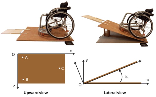
A MWC reference frame was defined with x-axis: antero-posterior pointing forward; y-axis: vertical pointing upward; z-axis: medio-lateral pointing toward the right; and the origin was chosen as the midpoint between the two contact points of the rear wheels with the platform. The definition of the MWC reference frame in the platform coordinates system, (through the two rear wheels contact points with the platform) then allows the 3 D location of the MWC CoM to be expressed in the local reference frame of the MWC.
2.2. Uncertainties evaluation
Uncertainties were quantified through a Monte-Carlo simulation (100 000 simulations) based on results obtained with a basket-ball MWC (Ottobock Invader). Variations were introduced with Gaussian distribution on measured masses (SD: 30 g on each kitchen scale), on each measurement point coordinates on the platform reference frame (SD: 3 mm in fore-aft and lateral direction), and on inclination angle (SD: 0.2°). Finally, variations on the points allowing to define the MWC local reference frame were also introduced (SD: 5 mm).
The standard deviations of the 100 000 calculated CoM expressed both in the platform coordinate system and in the MWC local reference frame, were retained as the uncertainties of the method.
2.3. Reliability
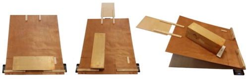
To evaluate the reliability, the method was applied on a known object (i.e., a wooden beam, size: 200 × 200 × 600 mm) placed in five positions on the platform (). The theoretical positions of the CoM for these 5 positions were then compared to their respective measured CoM locations.
Figure 2. photographs of three of the five conditions used for the reliability evaluation.
3. Results and discussion
3.1. Uncertainties evaluation
In both horizontal and inclined positions, the measured total mass was 11.614 kg. The CoM location was [34.2, 29.1, 44.8] (in cm) in the platform reference frame; and [8.9, 28.2, 0.3] (in cm) in the MWC reference frame.
Simulations showed uncertainties of 3, 8 and 2 mm, following x-, y- and z-axes, in the platform reference frame and 5, 8 and 4 mm following x-, y- and z-axes, in the MWC reference frame (including the uncertainty on the MWC position on the platform).
3.2. Reliability
Among all conditions, the measured total mass of the reference object ranged from 10.125 to 10.150 kg, excepted for one condition (the most rearward) where the measured total mass was 10.230 kg.
In the platform reference frame, average differences between theoretical and measured CoM locations were 4 mm in the horizontal plane (x- and z-axes) and 22 mm in the vertical direction. Maximal differences were 8, 28 and 5 mm following x-, y- and z-axes, respectively. However, it must be noted that the height of the reference object CoM was low (about 10 cm) that could limit the change in fore-aft distribution of the weight between the horizontal and inclined positions of the platform. Hence, it can be hypothesised that the reliability following the vertical direction would be slightly better with a MWC, without reaching the reliability obtained in the horizontal plane.
4. Conclusions
This study showed the ability of the method to determine 3 D-location of a MWC CoM with uncertainties of about 5 mm in the transversal plane, which is appropriate for this application. The vertical component is more sensitive to measurement errors but results could be improved by increasing the platform inclination angle. Improvements could also be achieved by a better location of the measurement points where the kitchen scales are placed, using an optimisation procedure, for instance.
Additional information
Funding
References
- Contoyannis B, Davis J, Ito M, Swan F. 2008. Determination of the vertical centre of mass of a wheelchair and occupant. Proceedings of the 2nd International Convention on Rehabilitation Enginnering & Assistive Technology; Bangkok (Thailand) 13–15 May 2008.
- Hybois S. 2019. Approche numérique pour l’optimisation personnalisée des réglages d’un fauteuil roulant manuel [PhD thesis]. ENSAM.
- Lemaire ED, Lamontagne M, Barclay HW, John T, Martel G. 1991. A technique for the determination of center of gravity and rolling resistance for tilt-seat wheelchairs. J Rehabil Res Dev. 28(3):51–58.
- Sauret C, Vaslin P, Lavaste F, de Saint Remy N, Cid M. 2013. Effects of user's actions on rolling resistance and wheelchair stability during handrim wheelchair propulsion in the field. Med Eng Phys. 35(3):289–297.
- Teran E, Ueda J. 2017. Influence of rolling resistance on manual wheelchair dynamics and mechanical efficiency. Int J Intell Robot Appl. 1(1):55–73.
- Wieczorek B, Górecki J, Kukla M, Wojtokowiak D. 2017. The analytical method of determining the center of gravity of a person propelling a manual wheelchair. Procedia Eng. 177:405–410.