
Abstract
The paper is focused on a design of mechanism accurately reproducing a complex motion in the sagittal plane of a human knee joint. The desired movement is modelled by applying specially designed shapes of cooperating cam elements based on the fixed and moving centroids of knee joint’s instantaneous centre of rotation. The mechanism’s CAD model and prototype are built using 3D printed elements, providing the possibility of interchanging the elements with cam profiles and adjusting the mechanism’s movement to individual needs. The mechanism movement is measured by analysing a video in Matlab and tracking colour markers on the prototype.
1. Introduction
The human knee joint movement is complex, even when it is simplified to main movements of flexion/extension in the sagittal plane. In this case, it is still not just a rotation between the thigh (femur bone) and shin (tibia bone), but a combination of roll and slide (Nägerl et al. Citation2008; ), with the range of motion (ROM) of approximately 0° to 120° (Bertomeu et al. Citation2007). As a result the movement trajectory of the femur in relation to tibia is rather complicated and does not retain a single position of instantaneous centre of rotation (ICR) (Bertomeu et al. Citation2007). In order to accurately obtain such movement, generally mechanisms with mobility higher than 1 degree of freedom (DOF) are required. Furthermore, this movement is specific for each individual person. For the above reasons, the best results of close and precise cooperation with knee joint, for instance in case of rehabilitation or movement assistance, can be achieved only if this complex motion is taken into consideration. For example, a personalized model for human knee joint was determined in (Nardini et al. Citation2020) on the basis of tomography, magnetic resonance and 3D-video-fluoroscopy. Widely, the knee joint movement is analysed by applying various techniques like cameras (Li et al. Citation2014; Geonea et al. Citation2015; Żuk and Pezowicz Citation2015;) including also stereophotogrammetry and usage of markers attached to body (Cappozzo et al. Citation2005; Lamine et al. Citation2017; Ferraresi et al. Citation2019), or IMU sensors (Seel et al. Citation2014; Olinski et al. Citation2016; Muraszkowski and Szrek Citation2017; Olinski et al. Citation2017), as well as extendable cable systems like in (Varela et al. Citation2015). Important conventions describing knee joint movement are low point kinematics shown for instance in (Kefala et al. Citation2022) and Grood and Suntay kinematics (Grood and Suntay Citation1983). However, it is hard to directly apply this kind of complex multidimensional data in the engineering design process. Therefore, in many cases this complex motion is represented by trajectory of movement of a chosen point on the lower limb, like for example femur’s point in (Wiczkowski and Skib Citation2008) or by trajectory of the knee joint’s ICR as presented in (Bertomeu et al. Citation2007; Terada et al. Citation2012; Bapat and Sujatha Citation2017).
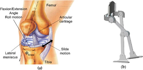
Figure 1. The knee joint (a) View of anatomy with complex motion in the sagittal plane (Moser Citation2013); (b) An example of 1DOF hinge knee from ALICE exoskeleton (Cardona et al. Citation2020).
Despite the above facts, many existing devices replicating knee structure reduce the knee joint movement to a simple rotation. These comprise knee orthoses/prostheses (Kapti and Yucenur Citation2006; Bera et al. Citation2020) or exoskeletons including knee joints like for example ALICE in () (Cardona et al. Citation2020), KARE-1 in (Kim et al. Citation2020), as well as robots and assisting lower extremity exoskeletons and their designs in (Liang et al. Citation2012; Kim et al. Citation2013; Lovasz et al. Citation2014; Geonea and Tarnita Citation2017; Iancu et al. Citation2018; Song et al. Citation2020). What is more, also some rehabilitation devices follow the same path. Knee joint movement is simplified to a hinge for instance in many continuous passive motion machines (CPM) as in (Trochimczuk et al. Citation2017; Mateas et al. Citation2018) or rehabilitation manipulators as presented in (Komada et al. Citation2009; Mohanta et al. Citation2017) Similarly, in a review article of devices for knee joint (Chen et al. Citation2019) most presented examples simplify the knee to a simple hinge.
On the other hand, there are already mechanisms and devices that try to mimic the complex knee motion, for instance by applying a 4-bar mechanism which is considered a good approximation of a knee joint as pointed out in (Farhat et al. Citation2010; Dathe et al. Citation2016; Hyun et al. Citation2017) Most of these devices include 1DOF mechanisms and are capable of achieving a trajectory only with approximation to the required one. Examples are devices like M-ICR Knee mechanism (Ho‐Jun Kim et al. Citation2020), a polycentric knee mechanism in (Poliakov et al. Citation2013; ) or devices based on a crossed 4-bar mechanism like in (Jourdan and Marc Citation2005; Kim et al. Citation2015; Bapat and Sujatha Citation2017) and similar Kincom in (Kim et al. Citation2012). In another example (Fu et al. Citation2016), a damping mechanism and a parallel spring are used within a 4-bar mechanism for a knee prosthesis, which resulted in a mechanism with DOF higher than 1. Several other mechanisms are also used in designs trying to reproduce the knee joint’s motion. These are for example gear mechanisms (Lovasz et al. Citation2014; Gastaldi et al. Citation2015), as well as cams or grooves (Terada et al. Citation2012; Terada et al. Citation2017) or even designs imitating the shapes of human tibia and femur bones (Hsu et al. Citation2006; Nägerl et al. Citation2008; Almouahed et al. Citation2017; Nabrdalik and Sobociński Citation2019; ).
Figure 2. Devices for knee joint taking into consideration its complex motion (a) Example of a device based on a 4-bar mechanism (Poliakov et al. Citation2013); (b) Example of a device based on bone shapes (Hsu et al. Citation2006).
This shows that the complex knee motion still remains a subject of research interest, which also proves that there is still a need for knee models and devices taking a complex motion characterization into consideration. The aim of this paper is to present a 1DOF novel mechanism, which is based on cams supplemented with ties, and its prototype which is discussed as being able to achieve the complex knee motion. In the following sections, the design concept of the mechanism is presented together with the built prototype and obtained results of performed experiments. The scope of the article is limited to the device’s motion, rather than its actuation. At the end advantages of new design are discussed.
2. Materials and methods
2.1. Design concept and mechanical system
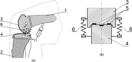
The concept concentrates on the knee movement in the sagittal plane in order to make the device less complicated, more stable and cheaper. The aim is to achieve sufficiently accurate and natural knee movement using relatively simple mechanism (1DOF) and avoiding a spatial mechanism or reproducing the anatomy of the human knee. In the presented manuscript orthotic application of the device is considered in the first place and therefore it is assumed that the knee movement would be sufficiently accurate if its deviation from the desired motion does not exceed 1 mm. From various possible mechanisms, the idea is to utilize a cam mechanism (2DOF kinematic pair restricted to 1DOF by usage of ties) in order to reproduce the anatomical movement of a knee joint in sagittal plane, especially by taking into consideration the trajectory of knee’s ICR. The design concept of the proposed device is presented in and . The main parts are two cooperating cams on the femur and tibia elements enabling to achieve a desired relative movement. In addition, the intention is to obtain a mechanism that could be simply adjusted to individual needs in terms of realizing specific trajectory of movement. Therefore, it is planned to use the cam shapes on interchangeable 3D printed elements ( – parts 3, 4) forming just the ends of the femur and tibia elements ( – parts 1, 2). The cam parts could be easily replaced with mechanical elements having other shapes with cooperating profiles suitable for each person. In addition, 3 ties ( – parts 5) are stretched between the two cams to ensure pure rolling without slipping with the aim of reducing the overall mobility of the device to 1DOF only. This is essential for achieving proper desired movement and realizing accurate full control with usage of just one actuator. For this reason, the ties constitute indispensable elements of the mechanism and need to work continuously. In addition, the ties are placed inside of guide grooves carved in the cam profiles and therefore do not affect the contact between cam surfaces. Furthermore, the springs ( – parts 6) are mounted on the sides of the knee mechanism to help to ensure continuous contact between cam profiles. Finally, the whole mechanism’s movement and flexion/extension of the knee is provided by linear actuator. Moreover, a patent application based on the presented design of knee joint mechanism has been prepared and the patent has been already granted (Kiwała et al. 2018).
Figure 3. Design of the mechanism’s kinematics (a) Side view with the cam mechanism’s elements and its linear actuator, where: 1 – femur, 2 – tibia, 3, 4 – interchangeable 3D printed elements with cam profiles (b) Cam mechanism’s cross-section with visible ties (5), guides and springs (6) (Kiwała et al. 2018).
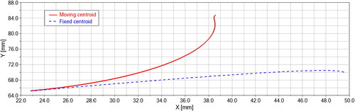
After the general concept of the mechanism has been determined the appropriate cam profiles are found and defined. It is decided to use the knee joint’s ICR trajectory from literature (Bertomeu et al. Citation2007; Bapat and Sujatha Citation2017) as the reference of human knee joint movement (target tibio-femoral kinematics). Furthermore, a knee model built in ADAMS software in previous research (Olinski Citation2017) is applied. The model is a crossed four-bar like linkage with controlled variable lengths of rockers. It has 3DOF, but is still a planar mechanism allowing movement only in sagittal plane. However, reproduced by the model movement, of femur in relation to tibia, can be considered ‘natural’, since the desired ICR trajectory in sagittal plane from (Bertomeu et al. Citation2007) results from knee joint’s 3D movements. This way the shapes of cam profiles are acquired. Specifically, the cam shape used on the femur is based on the moving centroid, i.e. ICR trajectory obtained in ADAMS, whereas the cam profile for the tibia is formed looking back at the fixed centroid to get the same trajectory as from literature (Bertomeu et al. Citation2007). Both centroids as cam shapes are presented in the graph () from a computed ADAMS simulation of the proposed concept.
Figure 4. The planned shapes of cooperating cam profiles, fixed centroid for tibia cam (dashed blue line) as from (Bertomeu et al. Citation2007), moving centroid for femur cam (red solid line) obtained from ADAMS.
2.2. Built prototype and test rig
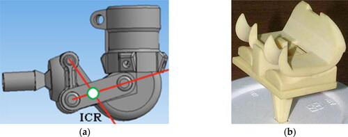
Determining the required shapes of cam profiles enabled designing a physical prototype of the proposed mechanism. The research prototype’s three-dimensional mechanical CAD model visible in and is drawn using Autodesk Inventor software. On the basis of this design the main parts: femur, tibia and the interchangeable cam elements with desired profiles were 3D printed. The assembled physical prototype of knee mechanism based on cams is shown in . At this stage of research low-extensible lines have been used as ties placed inside of guide grooves in cam profiles and an appropriately shaped flat spring has been applied on one side of the prototype to serve as the planned springs ensuring cams contact.
Figure 5. The knee joint cam mechanism prototype’s design as a 3D CAD drawing (a) Front view focusing on the interchangeable cam elements (b) Axonometric view further explaining the working principle by showing the cooperating cam profiles (3,4) and guide grooves (5).
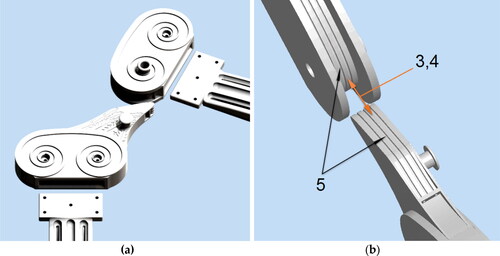
Figure 6. Physical prototype (a) Assembled with i.a. 3D printed elements with placed colour markers (b) Mounted in a stationary frame of the test rig together with the linear actuator, sensors and drawn coordinate systems applied for movements identification and calculations.

In order to test the designed and built prototype () an experimental rig has been prepared. The knee mechanism’s prototype has been attached to a stationary frame visible in , which is showing also the coordinate systems used for calculations. A linear motor imposing the flexion/extension movement of the prototype, controlled by Arduino Mega with a motor shield, has been applied. In the experimental trials, the movement starts from a fully extended knee joint (about 0 rad), but the first flexion till about 10th second of experiment, to a fully flexed knee e.g. in , constitutes the initial phase. Therefore, the movements and results should be examined from this point forward. In case of this experiment only the femur is moved whereas the tibia part remains stationary.
Furthermore, colour markers have been placed on the prototype in order to visually analyse the mechanisms movement and evaluate its performance, similarly to the cases presented in (Tappeiner et al. Citation2018; Lazăr et al. Citation2019) where, during robot-aided rehabilitation activities, a colour marker mounted on the hand of the participant was observed. For this reason the used test rig included also a whitescreen and a video recording device. The prototype is also equipped with IMU sensors. Two were placed on the femur and two on the tibia. Their results are not the subject of this work, but may occur useful in further evaluation of prototype’s performance for instance by checking the obtained angular accelerations, velocities, as well as the angular ROM of the knee’s flexion/extension.
Postprocessing of the obtained data is done with usage of Matlab’s Computer Vision System Toolbox. The experiments’ recordings captured at 30 frames/s are divided into individual images (frames). Each of them is analysed for finding the colour markers defined in RGB, which allows to track the markers movement in relation to the Matlab defined coordinate system ( – black XM, YM), located in upper left corner of analysed image. Furthermore, the results need to be scaled to the actual size of movement. This is done by applying a scaling factor obtained by performing a comparison of the Matlab measured distance (DISM) between two colour markers placed on tibia (stationary) and of the physical distance (DISR) between these markers on the prototype (). The obtained positions are also recalculated (with ΔX ≈ 310 mm, ΔY ≈ 202 mm in ) in order to achieve real initial positions of tracked markers. It means positions according to the origin of coordinate system ( – red XR,YR) assumed on the physical prototype from the stage when cam profiles were defined. No additional filtering or averaging of the obtained results for displacements, trajectories and angular movement has been applied.
3. Results
Experiments of the built prototype of the knee joint mechanism have been performed with 10 repetitions of the flexion/extension movement of the device as actuated by linear motor. The presented results in show data obtained from video analysis of two colour markers, red and green, placed on the femur element (tibia is stationary). More specifically, the and present the first step of measurement showing directly the positions of tracked markers. Whereas, presents the extracted clinically meaningful metric (flexion/extension angle). However, since the proposed prototype is a 1DOF planar mechanism, other knee movements are not achieved and therefore the mentioned clinically relevant description like Grood and Suntay kinematics cannot be properly applied here.
Figure 7. Placed on femur markers movements in relation to time (a) Red marker – horizontal x(t), (b) Red marker – vertical y(t), (c) Green marker – horizontal x(t), (d) Green marker – vertical y(t).
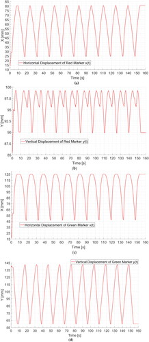
Figure 8. The trajectory of movement y(x) for (a) Red marker (b) Green marker.
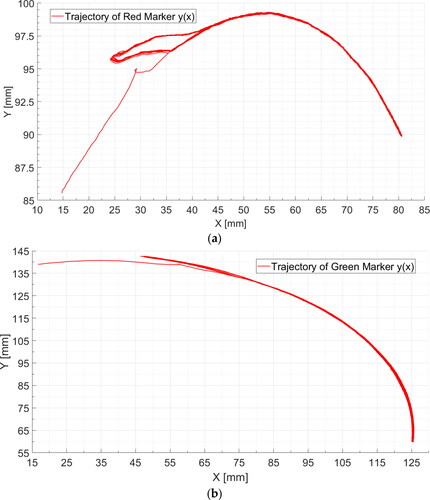
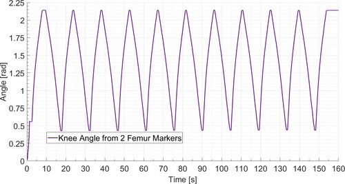
Figure 9. Knee joint flexion/extension angle calculated from the femur markers movement.
After performing the described in previous section postprocessing procedure the marker’s movements are presented as horizontal x(t) and vertical y(t) displacements in relation to time, respectively for the red marker ( and ) and green marker ( and ). Time is scaled after 30 images/s (samples/s) resulting from the 30 frames/s frequency of recording. Furthermore, movement trajectory plots y(x) for red marker () and green marker () have been shown.
The results of experiments have shown that the measured fluctuations in a stationary marker’s position did not exceed ±0,1 mm. This can be assumed as the accuracy of the applied video measurement and postprocessing method. During trials, the average velocity of green marker amounted to about 0,71 mm/frame. It means that for recording speed of 30 frames/s, some possible inaccuracies in measurements during movement can occur. However, since the main indicator of satisfactory results in case of presented research is the repeatability of the obtained extreme positions of the mechanism (corresponding to minimum and maximum flexion/extension), at these points the prototype’s movement was stopped for 0,5 s to allow for more accurate measurement. In terms of numbers, satisfying repeatability has been assumed as lower than 0,5 mm deviation of markers max. and min. positions between consecutive repetitions of movement. This has been proved with results in . For these reasons, as well as because the experimental movement was repeated 10 times, the obtained results are considered satisfactory and make the characterization of device’s performance feasible. Performing a more detailed statistical analysis could help to determine the accuracy of the marker positioning with the applied measurement method, but this was not the aim of this study.
In addition, by performing calculations combining displacement data of two moving markers it was possible to find the femur angular orientation which in this case could be equated to the knee joint’s flexion/extension angle (). The angles obtained for these consecutive movements range from about 0.43 rad to 2.14 rad (approximately from 24° to 122°).
Overall, good repeatability of prototype motion could be identified in consecutive repetitions of experimental movement of flexion/extension. It was found to be true both for the obtained displacements of 2 marker points ( and ), as well as for the angular ROM ().
4. Discussion and conclusions
The article presents a 1DOF novel cam based mechanism reproducing the complex human knee joint motion by imitating the relative movement between the femur and tibia of the lower limb. The novel mechanism’s kinematics and cam profiles are determined and a 3D model of the prototype is drawn in Inventor software. The main elements of the prototype are two cooperating cams fixed in the femur and tibia parts. Usage of a 2DOF cam kinematic pair restricted by ties to 1DOF allows to accurately realize the desired complex trajectory. Novel features of the design include among others the shapes of cams which are designed as based on the ICR trajectory. Specifically, the cams’ profiles are formed as the fixed and moving centroids of ICR, respectively for the tibia and the femur. Data about the reference ICR movement is used in a model in ADAMS software to achieve the desired movement of knee joint and find the centroids. There are many solutions of knee mechanisms, but these do not use the ICR moving and fixed centroids. The existing devices based on grooves or cams rather try to imitate the shapes of cooperating bone surfaces (Hsu et al. Citation2006; Nägerl et al. Citation2008). This kind of reference data may be more difficult to obtain than the knee’s ICR movements which can be acquired for each individual person and constitute an accurate and universal way to describe knee motion. Therefore, in the future, the analysis of kinematics is planned as a straightforward source of ICR data for designing cam profiles. For instance, movement of the patient’s healthy knee joint could be used. Furthermore, the proposed 1DOF device does not try to mimic the knee joint’s structure, but to reproduce the knee joint movement in sagittal plane. Using cam profiles based on ICR trajectory, instead of bone shapes allows also to reproduce the complex knee motion without the need to include slipping. The applied ties ensure that cams cooperate strictly with rolling on each other. Another important aspect, not present in many other knee joint solutions, is the fact that the mechanism can be easily and repeatedly adjusted to individual needs realizing different trajectories. The upper and lower cams constitute 3D printed interchangeable elements connected to femur and tibia respectively and can be replaced by elements with other shapes of profiles suitable for each person. The customization possibility is not straightforwardly proven in the article, but the idea of the current research is to demonstrate that the movement may be realized for particular individual case of knee’s ICR trajectory and adjusted to other required trajectories by changing the cam profile elements. The knee joint’s movement (ICR trajectory) is based on literature, but the cam profile shapes are derived from a numerical knee model built in Adams software. Results of this model simulations, presented in (Olinski Citation2017), have proven that different ICR trajectories could be accurately achieved. Therefore a conclusion is derived that on basis of individual needs (ICR trajectories) suitable cam profiles can be defined and this way various movements can be realised by the presented prototype, simply by changing the elements with cam profiles. For this reason, it is essential to obtain proper individual data of desired knee movement that can be used to define cam profiles adjusted to specific user. Knee devices, similar to presented prototype, which are to some extent universal and based i.a. on 1DOF 4-bar mechanisms (Kim et al. Citation2012; Poliakov et al. Citation2013; Ho‐Jun Kim et al. Citation2020) may only approximately realize the knee joint’s anatomical movement. Devices with higher mobility like shown in (Fu et al. Citation2016; Olinski et al. Citation2017; Olinski et al. Citation2021) are better in this matter and have their own potential, especially in some cases, but can be less stable and difficult to realise in application of small additional actuators, dampers etc. Furthermore, many of the more complex solutions including also spatial knee designs lack the proper interest in the knee joint’s movement including not only roll, but also slide. For this reason even if the movement is less constrained and these devices may be suitable for more applications, they may occur inferior to the proposed prototype in the aspect of reproducing anatomical movement in the sagittal plane.
The experiments, 10 repetitions of flexion/extension, of the designed and built cam prototype of the knee joint mechanism, are also executed showing promising results. Small hysteresis at the beginning of each flexion and end of extension movements can be noticed in the trajectories of the markers (), especially in plot of motion in Y axis (). This happens probably due to obtainment of not ideal continuous contact between the cam surfaces and occurrence of slip instead of pure rotation between them. The cause may be too low tension of the ties or the ties may extend too much. For the green marker the hysteresis is much less visible ( and ), since the whole movement of green marker is larger than for red marker. For this reason the hysteresis constitutes a smaller part of the whole displacement. Overall, this deviation of trajectory takes place only in a small part of the knee joint motion and does not affect the rest of the movement. Generally, a reasonable level of comparability could be found in successive experimental movements for the obtained displacements of markers, theirs trajectories and the angular ROM. The correctness of the prototype’s movement should be further confirmed by the obtained experimental data that could be used to calculate ICR trajectory and comparing it with the desired movement from literature. At this stage of research, the mentioned earlier 1 mm tolerance of deviation from the desired motion is only an arbitrary choice and assumption, since the results presented in the manuscript were evaluated mostly in terms of repeatability of the achieved measured movement. Both of these matters would need to be further investigated during thorough in vivo experiments with patients using the device and processed using RMS or other statistical method to compare the desired and achieved trajectories. This would be the final stage determining data about the accuracy of movement reproduction, as well as the appropriate value of permitted movement deviation based on clinical need.
Furthermore, the mechanism is capable of realizing the movement covering the whole required flexion/extension ROM (about 0° to 120°). This ability is visible in where at the beginning of experiment the device starts movement from about 0°. However, during the experiments the device’s ROM occurred to be limited to around 0.43/2.14 rad (about 24°/122°) min/max values of the flexion/extension angle (). Some jamming of the mechanism could be observed and the probable reason was the linear actuator. Since the paper’s focus is placed on the device’s motion, rather than its actuation, the applied in the prototype cylinder is not yet the final actuator intended for active usage with patients. It was applied in this research in order to apply stable and repeatable extortion of movement. In the future, a suitable actuator, capable of cooperating with patients, should be chosen and its points of connection to the prototype should be thoroughly evaluated and adjusted. Maybe even application of some intermediary mechanism between the actuator and prototype could be a solution to this issue.
Nonetheless, the current version of device made it possible to obtain the experimental characterization of the proposed prototype that has been elaborated with particular emphasis on the trajectory of movement of 2 chosen points of femur. Obtained plots prove that the prototype and the video analysis method work properly to an acceptable extent, but the accuracy of movement and measurement should be further evaluated by comparing the experimental results with other systems. Furthermore, it was observed that the results of video analysis were highly dependent on the illumination. In case of each experiment and marker’s colour the settings of analysing program, especially the range of permissible colours’ shades, had to be adjusted to enable correct marker displacement detection. This problem could be possibly overcome by applying in the future other versions of markers, for instance QR Code, resulting in improving the accuracy of measurement and shortening the time of postprocessing. More advanced measurement method should also be used utilizing a commercial motion capture system. A further comparison of results with another system for example based on a set of cameras, could evaluate the results more correctly and enable confirming the system’s accuracy. This is intended for future activity.
Moreover, it is anticipated that the proposed device should be able to improve the rehabilitation process when used as an orthosis or kinesiotheraphy aiding device, because it can reproduce very accurately the complex movement of the human knee. Usage of mechanism would probably increase the patient’s comfort and reduce the pain, as it offers a high level of compatibility with human knee movements. Since, the cam profiles are based on the knee’s ICR trajectory, it is possible to use similar data from other people in order to produce different shapes of cams and this way obtain knee movement suitable for each individual person.
Only first preliminary in vivo experiments utilizing the mechanism with humans have already been performed, but without the actuator, so the movement was enforced by the user. Depending on the application this is one of the potential ways that this device can be utilized as an orthosis stabilizing and restricting the knee movement. However, also when an actuator powered device would be used with humans, the movement motion according to a predefined function of flexion/extension, a kinematic extortion of movement, would be just one of the possible operating modes of the device (isokinetic mode). In the future it is intended to equip the device with sensors obtaining a mechatronic device that would be able to operate with actuator in other modes. These would include: cooperation mode – following patient movement or providing aid, resistive mode – training strength by keeping a set resistance level. For the above reasons, further work is required in order to better measure the degree of compatibility of the mechanism with human knee. For instance applying EMG sensors and comparing the muscles usage in cases of knee movement with and without the mechanism could bring interesting results. The possible applications of the mechanism include not only knee prosthesis and orthosis, but also among others endoprosthesis, exoskeleton or human knee movement simulator.
Acknowledgements
Author wishes to thank the staff and students at LARM, Cassino, Italy, for their support.
Disclosure statement
No potential conflict of interest was reported by the author.
Funding
The author(s) reported there is no funding associated with the work featured in this article.
References
- Almouahed S, Hamitouche C, Stindel E. 2017. Optimized prototype of instrumented knee implant: experimental validation. Innov Res BioMed Eng. 38(5):250–255.
- Bapat GM, Sujatha S. 2017. A method for optimal synthesis of a biomimetic four-bar linkage knee joint for a knee-ankle-foot orthosis. JBBBE. 32:20–28.
- Bera T, Rafique S, Isaksson M, Singla A, Jain P. 2020. Comparative study of knee joint torque estimations for linear and rotary actuators using bond graph approach for stand–sit–stand motions. Int J Adv Robot. Syst. 17:1–13.
- Bertomeu JMB, Lois JMB, Guillem RB, Pozo APD, Lacuest J, Mollà CG, Luna PV, Pastor JP. 2007. Development of a hinge compatible with the kinematics of the knee joint. Prosthet Orthot Int. 31(4):371–383.
- Cappozzo A, Della Croce U, Leardini A, Chiari L. 2005. Human movement analysis using stereophotogrammetry, Part 1: theoretical background. Gait Posture. 21(2):186–196.
- Cardona M, García Cena CE, Serrano F, Saltaren R. 2020. Conceptual development of a lower limb exoskeleton robot driven by an on-board musculoskeletal simulator. Sensors. 20(3):789.
- Chen B, Zi B, Wang Z, Qin L, Liao W-H. 2019. Knee exoskeletons for gait rehabilitation and human performance augmentation: a state-of-the-art. Mech Mach Theory. 134:499–511.
- Dathe H, Gezzi R, Fiedler C, Kubein-Meesenburg D, Nägerl H. 2016. The description of the human knee as four-bar linkage. Acta Bioeng Biomech. 18(4):107–115.
- Farhat N, Mata V, Rosa D, Fayos J. 2010. A procedure for estimating the relevant forces in the human knee using a four-bar mechanism. Comput Methods Biomech Biomed Eng. 13(5):577–587.
- Ferraresi C, De Benedictis C, Maffiodo D, Franco W, Peluso A, Leardini A. 2019. A methodology for the development of a Hinged Ankle-Foot Orthosis compatible with natural joint kinematics. In: Uhl T, editor. Advances in mechanism and machine science. mechanisms and machine science. Vol. 73. Cham: Springer. https://doi.org/10.1007/978-3-030-20131-9_10
- Fu H, Zhang X, Wang X, Yang R, Li J, Wang L. 2016. A novel prosthetic knee joint with a parallel spring and damping mechanism. Int J Adv Robot Syst. 13(4):1–9.
- Gastaldi L, Lisco G, Pastorelli S. 2015. Evaluation of functional methods for human movement modelling. Acta Bioeng Biomech. 17(4):31–38.
- Geonea I, Ceccarelli M, Carbone G. 2015. Design and analysis of an exoskeleton for people with motor disabilities. The 14th IFToMM World Congress; Taipei. Taiwan.
- Geonea ID, Tarnita D. 2017. Design and evaluation of a new exoskeleton for gait rehabilitation. Mech Sci. 8(2):307–321.
- Grood ES, Suntay WJ. 1983. A joint coordinate system for the clinical description of three-dimensional motions: application to the knee. J Biomech Eng. 105(2):136–144.
- Hsu YL, Hung YC, Yin JZ. 2006. Design of a novel total knee prosthesis using TRIZ. J Med Biol Eng. 26(4):177–185.
- Hyun DJ, Park H, Ha T, Park S, Jung K. 2017. Biomechanical design of an agile, electricity-powered lower-limb exoskeleton for weight-bearing assistance. Rob Auton Syst. 95:181–195.
- Iancu CA, Ceccarelli, M, Lovasz EC. 2018. Design and lab tests of a scaled leg exoskeleton with electric actuators. In: Ferraresi C, Quaglia G, editors. Advances in service and industrial robotics. Mechanisms and machine science. Vol. 49. Cham: Springer; p. 719–726.
- Jourdan F, Marc T. 2005. A numerical design of a knee brace based on a crossed bars mechanism. Comput Methods Biomech Biomed Eng. 8(sup1):151–152.
- Kapti AO, Yucenur MS. 2006. Design and control of an active artificial knee joint. Mech Mach Theory. 41(12):1477–1485.
- Kefala V, Ali AA, Hamilton LD, Mannen EM, Shelburne KB. 2022. Effects of weight-bearing on tibiofemoral, patellofemoral, and patellar tendon kinematics in older adults. Front Bioeng Biotechnol. 10:820196.
- Kim HJ, Lim DH, Kim WS, Han CS. 2020. Development of a passive modular knee mechanism for a lower limb exoskeleton robot and its effectiveness in the workplace. Int J Precis Eng Manuf. 21(2):227–236.
- Kim HJ, Noh J, Yang W. 2020. Knee-assistive robotic exoskeleton (KARE-1) using a conditionally singular mechanism for industrial field applications. Appl Sci. 10(15):5141.
- Kim JH, Han JW, Kim DY, Baek YS. 2013. Design of a walking assistance lower limb exoskeleton for paraplegic patients and hardware validation using CoP. Int J Adv Robot Syst. 10(2):113.
- Kim J-H, Shim M, Ahn DH, Son BJ, Kim S-Y, Kim DY, Baek YS, Cho B-K. 2015. Design of a knee exoskeleton using foot pressure and knee torque sensors. Int J Adv Robot Syst. 12(8):112.
- Kim KJ, Kang MS, Choi Y, Jang HY, Han J, Han C. 2012. Development of the exoskeleton knee rehabilitation robot using the linear actuator. Int J Precis Eng Manuf. 13(10):1889–1895.
- Kiwała S, Olinski M, Gronowicz A, Ceccarelli M, inventors. 2018 Sept 4. Mechanizm dla protezy kolana (Device of knee prosthesis). Poland Patent 238438.
- Komada S, Hashimoto Y, Okuyama N, Hisada T, Hirai J. 2009. Development of a biofeedback therapeutic-exercise-supporting manipulator. IEEE Trans Ind Electron. 56(10):3914–3920.
- Lamine H, Bennour S, Laribi M, Romdhane L, Zaghloul S. 2017. Evaluation of calibrated kinect gait kinematics using a vicon motion capture system. Comput Methods Biomech Biomed Engin. 20(sup1):111–112.
- Lazăr VA, Cafolla D, Pisla D, Carbone G. 2019. Design of a mechanical interface for a cable-driven rehabilitation device. In: Carbone G, Ceccarelli M, Pisla D, editors. New trends in medical and service robotics. Mechanisms and machine science. Vol. 65. Cham: Springer; p. 283–292.
- Li T, Ceccarelli M, Luo M, Laribi MA, Zeghloul S. 2014. An experimental analysis of overcoming obstacle in human walking. J Bionic Eng. 11(4):497–505.
- Liang C, Ceccarelli M, Takeda Y. 2012. Operation analysis of a Chebyshev-Pantograph leg mechanism for a single DOF biped robot. Front Mech Eng. 7(4):357–370.
- Lovasz EC, Ciupe V, Modler KH, Gruescu C, Hanke U, Maniu I, Mărgineanu D. 2014. Experimental design and control approach of an active knee prosthesis with geared linkage. In Petuya V, editor. New advances in mechanisms, transmissions and applications. Mechanisms and machine science. Vol. 17, Dordrecht: Springer; p. 149–156.
- Lovasz EC, Pop C, Pop F, Dolga V. 2014. Novel solution for leg motion with 5-link belt mechanism. Int J Appl Mech Eng. 19(4):699–708.
- Mateas M, Moldovan C, Gruescu C, Kis A, Lovasz EC. 2018. Novel rehabilitation system for the lower limb. IOP Conf Ser: Mater Sci Eng. 444:052021.
- Mohanta JK, Santhakumar M, Kurtenbach S, Corves B, Hüsing M. 2017. Augmented PID control of a 2PPR-2PRP planar parallel manipulator for lower limb rehabilitation applications. In: Corves B, Lovasz EC, Hüsing M, editors. New advances in mechanisms, mechanical transmissions and robotics. Mechanisms and machine science. Vol. 46, Cham: Springer. https://doi.org/10.1007/978-3-319-45450-4_39
- Moser S. 2013. Development of a variable knee joint [bachelor thesis]. Zurich (Switzerland): ETH.
- Muraszkowski A, Szrek J. 2017. The concept of mobile system of analysis and visualisation of human gait parameters. Proceedings of 23rd International Conference Engineering Mechanics; May 15–18; Svratka. Czech Republic. p. 678–681.
- Nardini F, Belvedere C, Sancisi N, Conconi M, Leardini A, Durante S, Parenti-Castelli V. 2020. An anatomical-based subject-specific model of in-vivo knee joint 3D kinematics from medical imaging. Appl Sci. 10(6):2100.
- Nabrdalik M, Sobociński M. 2019. The finite element method in the analysis of the stress and strain distribution in polyethylene elements of hip and knee joints endoprostheses. MATEC Web Conf. 254(02025):MMS 2018.
- Nägerl H, Frosch KH, Wachowski MM, Dumont C, Abicht CH, Adam P, Kubein-Meesenburg D. 2008. A novel total knee replacement by rolling articulating surfaces. In vivo functional measurements and tests. Acta Bioeng Biomech. 10(1):55–60.
- Olinski M. 2017. Synthesis of mechatronic systems supporting motion physiotherapy of lower limb joints [PhD thesis]. Wrocław (Poland): Wrocław University of Science and Technology.
- Olinski M, Ceccarelli M, Cafolla D, Gronowicz A. 2016. An experimental characterization of human knee joint motion capabilities. In: New trends in mechanism and machine science. Mechanisms and machine science. Vol. 43, Cham: Springer; p. 411–419.
- Olinski M, Gronowicz A, Ceccarelli M. 2021. Development and characterisation of a controllable adjustable knee joint mechanism. Mech Mach Theory. 155(104101):104101.
- Olinski M, Gronowicz A, Ceccarelli M, Cafolla D, et al. 2017. Human motion characterization using wireless inertial sensors. In Corves BJ editors. New advances in mechanisms; mechanical transmissions and robotics. Mechanisms and machine science. Vol. 46, Cham: Springer; p. 328–335.
- Olinski M, Gronowicz A, Ceccarelli M, Handke A. 2016. Design and characterization of a novel knee articulation mechanism. Int J Appl Mecha Eng. 21(3):611–622.
- Poliakov OM, Lazarev VB, Chepenyuk OO. 2013. Transfemoral prosthesis with polycentric knee mechanism: design, kinematics, dynamics and control strategy. J Rehab Robot. 1:109–123.
- Seel T, Raisch J, Schauer T. 2014. IMU-based joint angle measurement for gait analysis. Sensors (Basel). 14(4):6891–6909.
- Song B, Lee D, Park SY, Baek YS. 2020. A novel method for designing motion profiles based on a fuzzy logic algorithm using the hip joint angles of a lower-limb exoskeleton robot. Appl Sci. 10(19):6852.
- Tappeiner L, Ottaviano E, Husty ML. 2018. A cable-driven robot for upper limb rehabilitation inspired by the mirror therapy. In: Zeghloul S, Romdhane L, Laribi M, editors. Computational kinematics. Mechanisms and machine science. Vol. 50, Cham: Springer. https://doi.org/10.1007/978-3-319-60867-9_20
- Terada H, Makino K, Ishida K, Ichikawa M, et el. 2017. Development of an assisting instrument of standing-up motion using driving springs for elderly persons. In Corves BJ editor. New advances in mechanisms, mechanical transmissions and robotics. Mechanisms and machine science. Vol. 46. Cham: Springer. 10.1007/978-3-319-45450-4_42
- Terada H, Zhu Y, Suzuki M, Cheng C, Takahashi R. 2012. Developments of a knee motion assist mechanism for wearable robot with a non-circular gear and grooved cams. In Lovasz EC, Corves B, editors. Mechanisms, transmissions and applications. Mechanisms and machine science. Vol. 3. Dordrecht: Springer; p. 69–76.
- Trochimczuk R, Kuźmierowski T, Anchimiuk P. 2017. Study of CPM device used for rehabilitation and effective pain management following knee alloplasty. Int J Appl Mech Eng. 22(1):241–251.
- Varela MJ, Ceccarelli M, Flores P. 2015. A kinematic characterization of human walking by using CaTraSys. Mech Mach Theory. 86:125–139.
- Wiczkowski E, Skib K. 2008. Kinetic analysis of the human knee joint. BiolSport. 25(1):77–91.
- Żuk M, Pezowicz C. 2015. Kinematic analysis of a six-degrees-of-freedom model based on ISB recommendation: a repeatability analysis and comparison with conventional gait model. Appl Bionics Biomech. 2015:503713.