
 ?Mathematical formulae have been encoded as MathML and are displayed in this HTML version using MathJax in order to improve their display. Uncheck the box to turn MathJax off. This feature requires Javascript. Click on a formula to zoom.
ABSTRACT
This study focuses on the issue of hot mix asphalt patch repairs, the performance of which is greatly reduced by repair edge disintegration. This is caused by low interface temperatures which result in poor repair bonding between fill material and host pavement. Twenty-four pothole repairs, 45 mm in depth, comprising 12 static and 12 dynamic repairs heated for 10 min 15 s and 21 min 49 s, respectively have been investigated. Dynamic heating has been completed using an experimental infrared heater. Temperatures were measured at 11 locations on the repair interfaces during the pouring and compaction of the fill mix. Volumetric of asphalt mixtures were also investigated. The results demonstrated that for static repairs, the lowest maximum temperatures were located at corners and on vertical repair boundaries. It was found that high thermal contact resistance in these interfaces dramatically affect the temperature levels. However, the figures improved in dynamically heated repairs. Comparing dynamically heated repairs of 10 min 15 s and 21 min 49 s with static repairs, showed average corner temperatures increase 10.85–24.45°C and 29.51–36.73°C, respectively, with accompanying increases in vertical interface temperatures 34.97°C and 46.41°C, respectively.
1. Introduction
One of the major distresses in asphalt pavement is potholes. They can be locally developed and are created due to base or subgrade failure, poor drainage and poor workmanship during construction (Lavin Citation2003, Thom Citation2008). Hot or cold mix can be used as pothole filling, nevertheless, cold mixes tend to be less durable than hot ones. Usual compaction equipments are small and manually controlled rollers or vibrating plates (Thom Citation2008, Washington State Department of Transportation Citation2017). Sometimes, both rollers and plates are used to achieve the required density.
However, compaction of a thin layer of asphalt, such as that in many patching operations, has been always a struggle since there is not sufficient time available to compact the mix with temperatures reaching rapidly cessation levels (Thom Citation2008). Asphalt mixture temperatures, wind velocity and environmental conditions at the time of the repair will affect this rapid decrease in temperature. Furthermore, fast cooling can be mainly observed in the edges of the repair due to cold underlying asphalt layer resulting in low dense interfaces and weak points prone to premature failure (Dong et al. Citation2014, Byzyka et al. Citation2017b).
Heating the underlying layer, prior to pothole filling and compaction, could possibly enhance the bonding between the old cold pavement and the new hot-fill mix and decrease early edge disintegration and repair failure. Infrared, microwave or induction heating systems are used for this purpose and studied by other researchers (Clyne et al. Citation2010, Uzarowski et al. Citation2011, Freeman and Epps Citation2012, Leininger Citation2015, Obaidi et al. Citation2017). However, the use of heating technologies in pothole repair has been studied mainly from on-site observations under adverse weather conditions, not from laboratory tests. In addition, the temperatures developed in the pothole repair interfaces have not been thoroughly assessed and correlated to repair failure. Defining the distribution of temperatures in patching will determine effective pothole heating procedures that could possibly increase the repair bonding strength and durability.
As a result, the objective of this research is to quantify the temperatures in the repair boundary during pothole filling and compaction of static and dynamic repairs repaired using infrared heat. The results will direct future research goals on improving the performance and longevity of patching as a result of pothole pre-heating with infrared heat.
In this study, static repair is a non-heated repair constructed using common repair practice. Whereas dynamic repair is a repair during which the empty pothole excavation has been pre-heated with an experimental infrared heater prior to filling and compaction. The heater is presented in Byzyka et al. (Citation2017a). Its main features include two plates that are capable of heating asphalt independently by radiating heat at different heat powers; an advanced controller; and controlled infrared heat application with heater being at different offsets from the pavement, in motion or stationary above the repair.
The experiments were executed in a laboratory environment. Repair parameters such as pothole size, composition of asphalt mixtures and temperatures of fill mixtures were kept the same to minimise their effect on the performed repairs. Static and dynamic repairs were constructed as a pair in one slab for simultaneous comparison of interface temperatures between the repairs. The pothole cavities were artificially created. Therefore, the cutting, squaring up of the pothole excavation and its cleaning from water and debris that are usually performed in common patching was not essential.
2. Experiments
2.1. Experimental program
Table shows the executed experimental programme. Twelve slabs named as S1-S12 were built, and 24 potholes were repaired: 12 static repairs and 12 dynamic repairs. In dynamic repairs, the pothole excavation was pre-heated for 10 min 15 s and 21 min 49 s for different repairs using the experimental infrared heater described in Section 1. The heating times were derived from authors’ previous work described in Byzyka et al. (Citation2018). In their paper, shallow and deep potholes were subjected to dynamic heat for different heater – pavement configurations and the optimum heating method was found. The optimum heating time for shallow repairs such as those presented in this paper was found to be 10 min 15 s than 21 min 49 s. However, by studying an extended heating time, it ensures a comprehensive investigation of infrared heat application in patch repair.
Table 1. Experimental program.
The tests of this paper were conducted in order to develop an accurate temperature distribution profile at the interfaces of static and dynamic repairs. Six repetitions were performed for measurement of temperatures at mid-depth points in the vertical interfaces of static repairs. For the same type of repairs, six repetitions were also performed for measurement of temperatures at points located at the bottom corners of the repair and at the middle of the bottom repair interface. Whereas, for a similar scope of tests, for the dynamic repairs, three repetitions were done per pre-heating time (Table ).
2.2. Materials
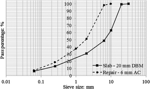
Twenty millimetre dense bitumen macadam (DBM) was used to simulate existing asphalt pavement. The mix comprised of granite coarse and fine aggregate and limestone filler. The bitumen used was 100/150 pen. The simulated potholes were repaired with 6 mm dense graded mixture (AC-6). Figure presents the gradation curves of the slabs and the pothole fill mixtures. The design of the described mixtures conforms to BS EN 13108, part 1 (British Standards Institution Citation2016b) and the binder complies with Manual of contract documents for Highway works, Volume 1, Specification for highway works (Department of Transport Citation2008). The preparation of the aggregate, filler and bitumen prior to mixing, the asphalt mixing, and the control procedure of the mix temperature conform with BS EN 12697, part 35 (British Standards Institution Citation2016a).
Figure 1. Gradation curves for asphalt mixtures.
2.3. Construction of slabs
A steel mould 700 mm × 700 mm × 150 mm was used to build the asphalt slabs of this study with final dimensions 695 (±5) mm × 695 (±5) mm × 100 (±5) mm (Figure ). The slabs were built upside down, in 12 asphalt batches of 7.6 kg each and compacted in two lifts of 50 mm deep using a vibrating plate in accordance with the Standard Code of Practice, New Roads and Street Works Act 1991, Specification for the Reinstatement of Openings in Highways (Department of Transportation Citation2010). The two lifts were bonded together by pre-heating the compacted first lift with the described infrared heater in Section 1 to an average surface temperature of 110°C (±10°C). The pre-heating time was 3 min and was performed prior to placement of the second lift. Each lift was compacted for 7 min.
Figure 2. Slab with pothole repairs: (a) moulds; (b) constructed slab; (c) demoulded slab and pothole excavations; (d) constructed pothole repairs: A is a static repair and B is a dynamic repair.
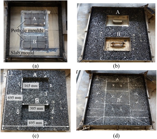
Two artificial pothole excavations were designed per slab. The size of the excavations was 305 (±2) mm × 165 (±2) mm × 45 (±2) mm. They were created putting two steel pothole moulds inside the slab mould prior to filling of it with asphalt mixture. The moulds, marked as A and B in Figure , indicate static and dynamic pothole repairs respectively. The moulds were removed using the infrared heater after 19 h of the construction of the slab.
During the construction of the slabs, aluminium tubes of 4 mm in diameter (Metals4u Citation2018) were put at varying locations inside the slabs. The tubes were used later to accommodate thermocouples for measurement of interface temperatures during the pothole repair operations. To measure temperatures in locations along the vertical repair interfaces, the tubes were put in between the asphalt batches of the first lift of the slab. This was performed for slabs S1–S6 shown in Table . Their positions were targeted to be in the middle of the respective interfaces. Whereas, to measure temperatures at the bottom of the repair, the tubes were placed at the top of the compacted first lift of the slab. This was performed for slabs S7–S12 presented in Table .
2.4. Static Pothole repairs
Twelve static repairs were performed for this set of tests. Real-time temperatures were captured using 11 T-type thermocouples of 0.5°C accuracy (Omega Citation2016), four located at the corners, four at the vertical repair interfaces and three at the bottom of the repair. The thermocouples were inserted in the aluminium tubes prior to commencing the repair of the potholes. Temperatures were measured during the pouring and the compaction of the fill mix. The ambient temperature was 20 (±3)°C and the starting temperature of the slabs, prior to patching, ranged from 17°C to 26°C.
To capture the temperatures at the vertical repair interfaces and corners, only the end of the thermocouples was exposed in the pothole excavation (thermocouples T1–T6, Figure (b)). Whereas, to capture the temperatures at the bottom of the repair, the thermocouples were extended in the pothole excavation by 85 mm (thermocouples T7–T11, Figure (c)). Six repetitions were executed for each temperature point measurement. The post-compaction coordinates of the tubes and thus the corresponding thermocouple locations during the thermal tests are given in Table . In this table, the sign ‘±’ for each location indicates the inclusive range of temperature point measurements between slabs S1–S16 or slabs S7–S12. The coordinate system for the thermocouple locations is shown in Figure (a,d). The origin of the coordinate system is put on the top left corner of the slab. The x-axis and z-axis are set to be the length (695 mm) and width (695 mm) of the slab respectively. Whereas the y-axis is put along the depth of the slab (100 mm).
Figure 3. Thermocouples in static and dynamic repairs completed for pothole A and B respectively: (a) slab and coordinate system for Table ; (b) thermocouples T1–T6 for measurement of temperatures in the vertical interfaces of the pothole repairs; (c) thermocouples T7–T11 for measurement of temperatures in the bottom of the pothole repairs; and (d) thermocouple routes from pothole excavations to data loggers.
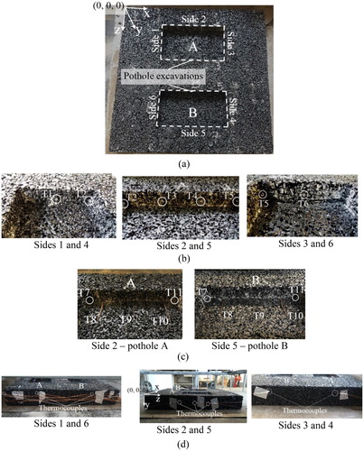
Table 2. Post-compaction thermocouple locations in the pothole excavation of static repairs in accordance with the origin of the coordinate system shown in Figure (a,d).
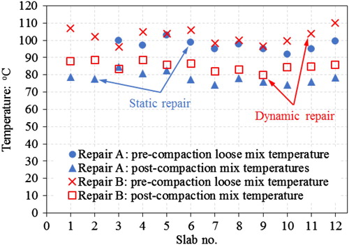
The static repairs were done as follows: Tack coat was applied in the pothole cavity 14 min prior to pothole filling to simulate tack coat application of real-time pothole repair. Then, hot mix asphalt was poured and evenly laid out. The mix was compacted for 6 min using a vibratory plate compactor. For the tack coat, a thin layer and rapid setting solution of bitumen in solvent was used. The temperatures of the fill mixes were monitored using an infrared camera Flir C2 (Flir Citation2018). These temperatures are presented in Figure . The figure shows also mixture temperatures for dynamic repairs to be discussed in the next section. Temperatures for slabs S1 and S2 not reported in Figure are due to error of the infrared camera during the measurements.
Figure 4. Pre- and post-compaction temperatures of pothole fill mixtures for static repair (Repair A) and dynamic repair (Repair B).
2.5. Dynamic pothole repairs using an experimental infrared heater
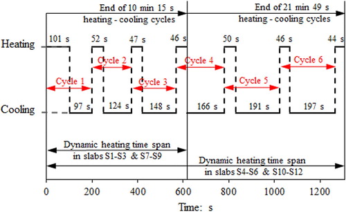
Twelve dynamic repairs were constructed. The dynamic heating of the repairs was done using the optimum pre-heating method discussed in Section 2.1. According to this method, dynamic heating is applied in heating–cooling cycles with the infrared heater operating stationary above the pothole excavation with 6.6 kW heat power. The six repairs completed in slabs S1–S3 and S7–S9 were pre-heated for 10 min 15 s. The other six repairs completed in slabs S4–S6 and S10–S12 were pre-heated for 21 min 49 s. The duration of each heating and cooling times is shown in Figure .
Figure 5. Dynamic heating cycle times for 10 min 15 s and 21 min and 49 s heating times.
The interface temperatures were captured using the same T-type thermocouples as in the static repairs. This is shown in Figure . The preparation of the thermocouples, the ambient temperature during the repairs and the slab temperatures prior to repair were the same with the static repairs previously described. The ambient and slab temperatures were the same because the static and dynamic repairs for each slab were performed the same day. In addition, the post-compaction coordinates of the tubes and thus the corresponding thermocouple locations for dynamic repairs are given in Table . The origin of the coordinate system is the same with that of the static repairs shown in Figure (a,d).
Table 3. Post-compaction thermocouple locations in the pothole excavation of dynamic repairs in accordance with the origin of the coordinate system shown in Figure (a,d).
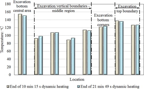
The construction process of the dynamic pothole repairs was done as follows. The infrared heater was put above the pothole excavation at an offset of 230 mm. Then, dynamic heating was applied. Immediately after pre-heating, the fill material was poured into the pothole excavation and compacted for 6 min. No tack coat was used during these repairs. The mixture temperatures are shown in Figure . The temperatures captured in the pothole excavation at the end of the two different time spans of dynamic heating are shown in Figure .
Figure 6. Temperature profile over time in the empty pothole excavation at the end of dynamic heating.
3. Volumetric of slabs and repairs
Slabs S1–S6 and their repairs were cored to evaluate the physical and mechanical properties of the test slabs. Nine cores were obtained per slab and three cores per pothole repair. Thereafter, the bulk specific gravity (Gmb) was determined using AASHTO T166, method A (American Association of State Highway and Transportation Officials Citation2007). The maximum theoretical specific gravity (Gmm) was calculated with Equation (1) (Roberts et al. Citation1991) and the air voids content was found with Equation (2).(1)
(1) where WT = total eight of asphalt mixture, gr; Wagg = weight of aggregate, gr; WAC = weight of total asphalt binder, gr.
(2)
(2) where VTM = voids in total mix, %.
4. Results and analysis
4.1. Volumetric
Figure presents the air voids content of the compacted slabs S1–S6 and of the static and dynamic pothole repairs built in them. The figure shows values from the average of nine cores per slab for all slabs and three cores per repair for all executed repairs. The number of cores depended only on how many cores could be taken from the constructed slabs and repairs.
Figure 7. Air voids content of slabs S1–S6 and their corresponding repairs.
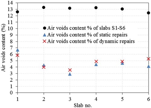
The results show that the air voids content of the slabs ranged from 12.43% to 13.28% showing no significant variation. The standard deviation (SD) of slab air voids content was found equal to 0.33%, 1.86%, 0.80%, 0.81%, 0.70% and 0.64% for slabs S1, S2, S3, S4, S5 and S6, respectively. Lower air voids content were observed for the executed repairs. Air voids in static repairs (2.91– 6.70%) showed higher variation than in dynamic repairs (3.56– 5.86%) although pre-compaction mix temperatures for static and dynamic repairs were measured to be at similar levels (97.8 and 100.6°C in average, respectively) and compaction time was also the same for all repairs. The SDs of the air voids content of the six static repairs built in slabs S1–S6 were found equal to 0.78%, 1.00%, 0.18%, 0.50%, 0.42% and 0.86%. The SDs of the air voids content of the six dynamic repairs built in slabs S1–S6 were found equal to 0.97%, 0.20%, 0.79%, 0.72%, 0.16% and 0.35%. Finally, it should be noted that the effect of pothole pre-heating in the air voids of slabs and dynamic repairs was not investigated. However, the issue was acknowledged by Norambuena-Contreras and Garcia (Citation2016) in their study for the effect of microwave and induction heating in asphalt mixture air voids and is suggested by the authors for future study.
4.2. Temperatures in repair interfaces
The temperatures recorded at the repair interfaces are presented in Figure . The results present temperature profile over time and are divided into 11 graphs: one graph per thermocouple with positions given in Tables and . For each thermocouple, the temperatures at the interfaces of static repairs are reported together with temperatures for dynamic repairs. Signal noise of thermocouples captured during the tests is also presented. This was observed mainly during the compaction of dynamic repairs and for thermocouples located in corners and vertical sides of the repairs. The disturbance of the thermocouples is attributed mainly to the softening of the asphalt during pothole pre-heating and secondary to the aggregate reorientation and forces applied during compaction.
Figure 8. Temperature profile over time for static and dynamic repairs during pothole mix filling and compaction.
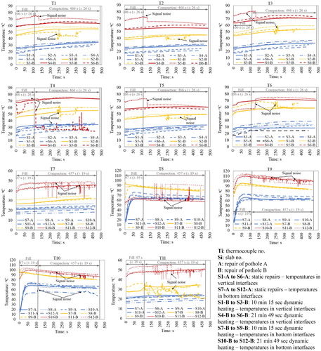
Between static and dynamic repairs with 10 min 15 s and 21 min 46 s pre-heating time, post-compaction temperatures in the vertical interfaces averaged 33.35°C, 57.11°C and 69.85°C, respectively (see T1, T3, T4 and T6 in Figure 6.14). Whereas, at the bottom of the repair (See T8-T10 in Figure ) temperatures averaged 62.89°C for static repairs, 81.04°C for dynamic repairs with 10 min 15 s pre-heating time and 85.26°C for dynamic repairs with 21 min 46 s pre-heating time.
The lowest temperatures were observed at the corners of all executed repairs. Points located at the bottom corner of the repairs (T7 and T11 in Figure ) averaged 22.57°C for static repairs, 30.91°C for dynamic repairs with 10 min 15 s pre-heating time and 48.06°C for dynamic repairs with 21 min 46 s pre-heating time. There was a small increase in corner temperatures at higher points along the vertical side of the repairs, increasing from bottom to top. An average temperature 27.61°C was measured for static repairs, 46.41°C for dynamic repairs with 10 min 15 s pre-heating time and 58.86°C for dynamic repairs with 21 min 46 s pre-heating time.
As it was seen from the results, temperatures measured at points located at the vertical repair interfaces of the static repairs were lower than that of dynamic repairs. This happened because of the following. When two solid bodies of different temperatures are in thermal contact, energy is transferred from the hotter to the cooler body. At the interface of these bodies, there is a temperature drop which is caused by surface roughness and non-flatness. In areas where there is a contact between the two surfaces, heat is transferred by conduction. In the void spaces of this interface, heat is transferred by convection and radiation. Thus, the actual contact area is significantly smaller than the apparent contact area. This contact limitation at the interface creates a thermal contact resistance (Janna Citation1999).
The inverse of thermal contact resistance is thermal contact conductance. Thermal contact conductance can be calculated by the ratio of the conductivity of the material over its thickness and it is expressed in W/m2 K. The higher the thermal conductance, the lower the thermal resistance at the interface. Thermal conductance is influenced by the characteristics of the two surfaces in contact such as surface deformation, surface cleanliness, surface roughness, waviness and flatness (Gilmore Citation2002), the contact pressure between the two bodies and any conducting fluid (fluids or gases) in the voids spaces of the bodies’ interface (Cooper et al. Citation1969).
In non-heated repairs such as the case of static repairs built it this study, low dense interfaces are created due to cold underlying layer pavement during placement of hot-fill material (Thom Citation2008). However, in pre-heated repairs such as the case of dynamic repairs investigated in this study, the air voids at the repair interfaces are decreased due to the pre-heating taking place prior to filling of the pothole excavation with the hot-fill material. Although this was not evaluated in this study, past studies conducted by Huang et al. (Citation2010) and Williams (Citation2011) confirm this.
Therefore, between static and dynamic repairs, higher air voids at the interface of static repairs means less contact areas exist between the slab and the fill material and the repair interface temperatures are lower than in dynamic repairs as shown from the experimental results (Figure ). The opposite happens in dynamic repairs where due to pre-heating, the air voids decrease, the contact areas increase and the repair interface temperatures increase too.
The results also showed that temperatures at the bottom of the repair for both static and dynamic repairs were higher than temperatures at the vertical sides of the repair. This is expected to have happened because when compaction force is applied during the repair, the pressure at the vertical interfaces of the repair is expected to be less than at the bottom of the repair. This increases the thermal resistance at the vertical interfaces which consequently affects the temperatures and creates cooler vertical repair boundaries than the bottom of the repair.
5. Conclusions
In this paper, the advantage of controlled pre-heating of excavated asphalt surface prior to patch repair, referred as ‘dynamic repair’ was investigated. Temperatures at the interfaces of static repair (non-heated) and dynamic repair were investigated in the laboratory using extractable thermocouples. Temperatures were measured during the pouring of the fill mixture into the excavated potholes and compaction. The following conclusions are drawn from the research:
Temperatures in the interfaces of hot mix asphalt pothole repairs were non-uniformly distributed. The lowest temperatures were received in vertical interfaces and corners of the repairs. This was evident mainly in static repairs.
Same amount of temperature increase was observed in repair interfaces with initial air and slab temperatures 20 (±3)°C and 17°C–26°C, respectively.
Dynamic heating did not considerably increase temperatures in corners of the repair. However, this figure was improved in vertical interfaces along the length and width of the repairs.
Comparing dynamically heated repairs of 10 min 15 s and 21 min 49 s with static repairs, showed average corner temperatures increases 10.85–24.45 and 29.51–36.73°C respectively, with accompanying increases in vertical interface temperatures 34.97°C and 46.41°C, respectively.
The low in temperature vertical interfaces of static repairs was attributed to high thermal contact resistance in contrast with the bottom of the repair.
The thermal contact resistance seemed to decrease in dynamic repairs. This due to higher actual contact spots in the repair interface, lower air voids and lower thermal contact resistance.
Temperature increases in the interfaces of dynamic repairs is expected to increase compaction effectiveness, interface bonding and patching longevity. However, further investigation is needed to prove this which would include the evaluation of the interface shear strength and rutting resistance.
Acknowledgement
Nynas UK AB and Conexpo (NI) Ltd supported by providing materials. Thermtest company supported in thermal conductivity instrument testing. Laboratory work was supported by Brunel University technical staff Neil Macfadyen and Simon Le Geyt and undergraduate students Albert Phillipson and Kamal Ahmad.
Disclosure statement
No potential conflict of interest was reported by the authors.
ORCID
Juliana Byzyka http://orcid.org/0000-0002-5570-8909
Correction Statement
This article has been republished with minor changes. These changes do not impact the academic content of the article.
Additional information
Funding
References
- American Association of State Highway and Transportation Officials, 2007. AASHTO T166: 2007. Bulk specific gravity of compacted asphalt mixtures using saturated surface – dry specimens.
- British Standards Institution, 2016a. BS EN 12697-35:2016. Bituminous mixtures, Test methods, Laboratory mixing.
- British Standards Institution, 2016b. BS EN 13108-1: 2010. Bituminous mixtures – material specifications.
- Byzyka, J., Chamberlain, D.A., and Rahman, M, 2017a. Development of advanced temperature distribution model in hot-mix asphalt patch repair. Proceedings of the Institution of Civil Engineers – Transport, 1–11. doi: 10.1680/jtran.17.00022
- Byzyka, J., Rahman, M., and Chamberlain, D.A, 2017b. Thermal segregation of asphalt material in road repair. Journal of Traffic and Transportation Engineering (English Edition), 4 (4), 360–371. doi: 10.1016/j.jtte.2017.05.008
- Byzyka, J., Rahman, M., and Chamberlain, D. A, 2018. An innovative asphalt patch repair pre-heating method using dynamic heating. Construction and Building Materials, 188, 178–197. doi: 10.1016/j.conbuildmat.2018.08.086
- Clyne, T.R., Johnson, E.N., and Worel, B.J, 2010. Use of taconite aggregates in pavement applications. Saint Paul: Minnesota Department of Transportation.
- Cooper, M., Mikic, B., and Yovanovich, M, 1969. Thermal contact conductance. International Journal of Heat and Mass Transfer, 12 (3), 279–300. doi: 10.1016/0017-9310(69)90011-8
- Department of Transportation, ed., 2010. Standard Code of Practice, New Roads and Street Works Act 1991. Specification for the Reinstatement of Openings in Highways.
- Department of Transport (UK), 2008. Manual of contract documents for Highway works. Volume 1, Specification for highway works, Series 900 Road pavements – Bituminous bound materials [online]. Available from: http://www.standardsforhighways.co.uk/ha/standards/mchw/vol1/pdfs/series_0900.pdf [Accessed 6 August 2018].
- Dong, Q., Huang, B., and Zhao, S, 2014. Field and laboratory evaluation of winter season pavement pothole patching materials. International Journal of Pavement Engineering, 15, 279–289. doi: 10.1080/10298436.2013.814772
- Flir, 2018. Compact Thermal Camera FLIR C2 [online]. Available from: https://www.flir.com/products/c2/ [Accessed 12 July 2018].
- Freeman, T.J., and Epps, J.A, 2012. Heatwurx patching at two locations in San Antonio. Austin: Texas Department of Transportation.
- Gilmore, D., ed., 2002. Spacecraft thermal control handbook, Volume I: fundamental technologies. El Segundo: Aerospace Press.
- Huang, B., et al., 2010. Evaluation of longitudinal joint construction techniques for asphalt pavements in Tennessee. Journal of Materials in Civil Engineering, 22 (11), 1112–1121. doi: 10.1061/(ASCE)MT.1943-5533.0000123
- Janna, W.S., ed., 1999. Engineering heat transfer. Boca Raton: CRC Press.
- Lavin, P., 2003. Asphalt pavements: a practical guide to design, production and maintenance for engineers and architects. London: CRC Press.
- Leininger, C.W., 2015. Optimization of the infrared asphalt repair process. Thesis (Master’s). University of Maryland [online]. Available from: https://search.proquest.com/openview/5d63e8ff20aa8561ec9f4e81b6fc75fe/1?pq-origsite=gscholar&cbl=18750&diss=y [Accessed 20 June 2018].
- Metals4u, 2018. 1/4” od x 16swg wall Aluminium tube. Available from: https://www.metals4u.co.uk/aluminium/c1/tube/c22/6.3mm-x-1.6mm-(-14-od-x-16swg-)/p3107 [Accessed 12 July 2018].
- Norambuena-Contreras, J., and Garcia, A, 2016. Self-healing of asphalt mixture by microwave and induction heating. Materials and Design, 106, 404–414. doi: 10.1016/j.matdes.2016.05.095
- Obaidi, H., Gomez-Meijide, B., and Garcia, A, 2017. A fast pothole repair method using asphalt tiles and induction heating. Construction and Building Materials, 131, 592–599. doi: 10.1016/j.conbuildmat.2016.11.099
- Omega, 2016. Hermetically sealed thermocouple [online]. Available from: http://www.omega.co.uk/pptst/HSTC.html [Accessed 14 May 2016].
- Roberts, F.L., et al., 1991. Hot mix asphalt materials, mixture design and construction. Lanham, MD: National Asphalt Pavement Association Education Foundation.
- Thom, N, 2008. Principles of pavement engineering. London: ICE Publishing.
- Uzarowski, L. et al., 2011. Innovative Infrared Crack Repair Method. 2011 Conference and exhibition of the Transportation As-sociation of Canada. Transportation successes: Let’s build them. 2011 Congress et Exhibition de l'Association des Transports du Canada. Les Succes en Transports: Une Tremplin vers l'Avenir.
- Washington State Department of Transportation, 2017. Maintenance manual M 51. Washington, D.C.: Washington State Department of Transportation.
- Williams, S.G., 2011. HMA longitudinal joint evaluation and construction. Arkansas: University of Arkansas.