Abstract
Many automotive components of gears, power transmissions, and engines are made of chrome molybdenum steel, which has high wear resistance. The life of automobiles depends on the life of such components. In order to extend the life of components, it is important to know the mechanism of wear of metallic parts. Many studies have been conducted on the wear mechanisms. Recently, we found a unique crystalline structure that cannot be explained by the established metallurgical theory in the course of transmission electron microscope (TEM) examination of the grain structures 0.2 to 1 μm deep from the sliding surfaces of a tested transmission part.
The original body-centered cubic (BCC) crystal changed to very fine face-centered cubic (FCC) crystal in the region just under the sliding surfaces. It is still not known why such a unique change was caused, but this is an intermediate report of our findings. This article discusses the relation between the unique transformation of the crystalline structure and formation of cracks, which led to production of fish-scale thin wear particles.
INTRODUCTION
Friction causes energy losses, and wear of machine parts shortens the life of machinery. Therefore, many attempts have been made to reduce friction and wear of machine elements, and many papers dealing with wear and cracks have been published. The area of studies on friction and wear is very broad and can be divided into unlubricated conditions and lubricated conditions. The former mainly deal with the mechanism of abrasive wear and adhesive wear. The latter cover the range of studies from the influence of lubricants and additives on friction and wear to the mechanism of wear of the sliding surfaces and crack formation below the sliding surface and, further, to the transformation of the material structure using scanning electron microscopy (SEM), X-ray diffraction, and transmission electron microscopy (TEM).
Many papers regarding wear and cracks under lubricated conditions have been published in Tribology Transactions in the past 10 years. Fereimanis, et al. ( Citation 1 ) studied the influence of temperature on wear mode for titanium aircraft engine components and showed that a different coating deterioration mechanism works on titanium materials at low temperatures than at high temperatures. Wong, et al. ( Citation 2 ) studied formation of antiwear films of antiwear hydraulic oils but the study was limited to the observation of the surface wear scar. Yoon, et al. ( Citation 3 ) studied the surface and subsurface of SAE 50B38 steel by SEM and TEM to understand mechanisms of scuffing and hypothesized that the formation of macroscopic adhesion at the sliding surfaces led to the plastic shearing of bulk material, causing scuffing, and that the transformed layer had the grain structure change during scuffing failure. Kovalchenko, et al. ( Citation 4 ) investigated the sliding friction and wear mechanism of silicon under conditions of both dry and lubricated sliding and showed that the major mechanism of wear of silicon was phase transformation.
Yoshizaki, et al. ( Citation 5 ) examined whether the tooth surface strength of gas-carburized gears made of Cr-Mo alloy steel could be improved by the abnormal surface layer and demonstrated that the tooth surface strength was increased by the characteristics of the abnormal surface layer. Oyamada and Inoue ( Citation 6 ) investigated the wear properties and wear processes of a JIS-FC250 cast iron surface coated with manganese–phosphate using SEM–energy dispersive X-ray spectrometry (EDX) surface analysis and found that the wear rate was different depending on the exposure parameter M of iron to the coating on the surface. Zhang, et al. ( Citation 7 ) examined the surface and the subsurface of a piston pin and piston that failed in scuffing and inferred that scuffing might initiate on a single asperity to lead to microscuffing when its flash temperature exceeds a critical temperature and that the asperities would be affected and more asperities might scuff when the thermal influence of the scuffed asperity raises its neighboring asperity temperature to a critical value.
Evans, et al. ( Citation 8 ), ( Citation 9 ) examined boundary-lubricated tapered roller bearing inner ring (cone) surfaces by TEM and SEM and showed that the surfaces of the tested bearings lubricated with base oil had small cracks but that the surfaces of the bearing lubricated with oil having antiwear additives had no cracks and that the fine grain of the near-surface material was mostly ferrite with a body-centered cubic (BCC) construction, although martensite and austenite construction were found at only depth exceeding 2 μm. Warren and Guo ( Citation 10 ) studied the effects of a white layer and associated residual stress on rolling contact stresses and strains by developing a finite element analysis simulation model of rolling contacts incorporating machining-induced surface integrity and demonstrated that the maximum normal stresses were located on the component surface but that the maximum von Mises stresses and shear and equivalent plastic strains are located below the phase-transformed layers.
Itoh, et al. ( Citation 11 ) investigated the mechanism of the zinc dialkyl dithiophosphate (ZDDP) tribofilm formation on iron oxide and revealed that the ZDDP molecules physically adsorbed on the iron oxide surface at room temperature but that the ZDDP molecules decomposed above 333 K and the zinc ions generated by decomposition of ZDDP adsorbed on the iron oxide surface. Rahman, et al. ( Citation 12 ) studied acoustic emission technology to detect rolling contact fatigue and claimed that the combination of an acoustic emission (AE) source locator and the AE data analyzer could be used as a useful tool for determining the incipient damage in rolling element. Lin, et al. ( Citation 13 ) studied oils with a low phosphorous concentration for the future requirements of fuel economy and emission control and demonstrated that the prototype engine oil with 0.05% P and no supplemental additives did not show any benefit in reducing friction, although it showed the best wear resistance; in addition, they found that organomolybdenum ester was effective in reducing friction in low-phosphorus engine oils although increased wear was possible.
Liew ( Citation 14 ) investigated the wear of uncoated, physical vapor deposition (PVD)-coated, and chemical vapor deposition (CVD)-coated carbide tools in the ultraprecision machining of AISI 420 stainless steel at low speeds and demonstrated that a PVD-coated tool is more suitable in ultraprecision machining of stainless steel with better accuracy and surface finish and that the use of liquid paraffin oil and cyclomethicone as a lubricant reduced flank wear, prevented surface fracture, and improved surface finish. Goto, et al. ( Citation 15 ) conducted an extensive literature survey on friction and wear of aluminum silicon alloy–impregnated graphite composite (ALGR-MMC) and its component matrices, graphite, Al-Si alloy in contact with bearing steel and also conducted their own tests using a pin-on-disk test rig to compare the data from the literature. They claimed that ALGR-MMCs with graphite contents in the range of 25–75 vol% had the best tribological performance, although the literature suggested that the optimal graphite content of ALGR-MMC was in the range of 50–100 vol%. They also reported that the friction coefficient and wear rate of graphite decreased with augmentation of the amount of the oil supplied for lubrication, although no breakdown of the oil film or damage of the counterpart surface was observed.
Toparli, et al. ( Citation 16 ) investigated the tribological behavior of CuSn coating, which was formed by the electric arc spray technique on an Ni alloy coating-deposited carbon steel at different loads under dry and lubricated environments using a pin-on-plate–type test apparatus and found that the critical force and adhesion strength of the CuSn coating was 11.82 mN and that friction coefficient values were lower and the decrease in surface roughness after the wear tests was lower in the lubricated environment than under dry conditions. Rasoda, et al. ( Citation 17 ) experimentally investigated spall propagation using a Rockwell hardness indenter with a 150 kg load across the inner raceway of angular contact new ball bearings at 2.65 GPa maximum Hertzian stress until the vibration exceeded the accelerometer's 1.0 g threshold, indicating the formation of a small spall, and monitored the spall growth rate using an in-line oil debris monitor mounted on the oil scavenge line. The spall propagation was confirmed by comparing the weight loss of the inner raceway before and after tests.
Guo and Walker ( Citation 18 ) investigated the friction coefficient of white layers on a machining surface by turning and grinding and found that a turned white layer slightly decreased the friction coefficient but a ground white layer significantly increased it under dry conditions, although the turned white layer slightly increased the friction coefficient, whereas the ground white layer slightly decreased it under lubricated conditions. Cho, et al. ( Citation 19 ) investigated modification of the surface roughness and the surface coating on the piston skirt to reduce frictional loss and the amount of wear and confirmed that surface roughness caused frictional losses and wear losses due to asperity interaction and that the friction coefficient of the graphite coating was lower than that of diamond-like carbon coating but that the graphite coating was less effective in protecting the surface of piston skirt. Leonard, et al. ( Citation 20 ) investigated the effects of fretting on steel surfaces coated with tungsten carbide–reinforced amorphous hydrocarbon (WC/a-C:H) and chromium nitride (Cr2N) in both grease-lubricated and unlubricated environments and confirmed that both coatings reduced fretting wear and that WC/a-C:H was more effective at reducing wear under unlubricated conditions and decreased fretting wear more than Cr2N when delamination was avoided in grease-lubricated contacts.
Fig. 1 Examples of typical surfaces of tested transmission components (color figure available online).

Li, et al. ( Citation 21 ) investigated the friction and wear properties of laser surface texturing and surface molybdenizing of duplex-treated, single-treated, and untreated Ni-base alloys on a ball-on-disk tribometer by rubbing against an alumina ceramic ball from room temperature to 873 K in order to improve wear resistance at high temperature and demonstrated that the friction coefficient of molybdenizing was reduced at room temperature but that of texturing was reduced at 873 K and that the wear rate of texturing was reduced at temperatures below 873 K and that of molybdenizing was reduced at 873 K due to the formation of lubricious oxide. Wei, et al. ( Citation 22 ) experimentally studied lubrication of four kinds of powders of polytetrafluoroethylene, graphite MoS2, and ball-like copper using a plane contact tribometer and demonstrated that the friction coefficient and wear decreased for polytetrafluoroethylene, graphite, and MoS2 but ball-like copper were worse with increasing load capacity, although it had certain antifriction effects at lower load capacity.
Papers from other journals were also examined. Suh ( Citation 23 ) overviewed the delamination theory of wear in relation to plastic deformation of the surface layer, crack nucleation, and crack propagation. Flaming and Suh ( Citation 24 ), ( Citation 25 ) presented a mathematical model of subsurface crack propagation in sliding contacts and showed that there is a characteristic crack propagation depth below the surface that increases with increasing coefficient of friction. They also performed an experimental study on delamination wear with aluminum alloys and showed that the alloy with a higher hardness (by 25%) had a faster crack propagation rate (3–10 times) in normal fatigue tests than the softer alloy and that the wear rate correlated with the crack propagation rate. Davies and Williams ( Citation 26 ) studied thermodynamically stable cavities in material by annealing and found that the growth of the dislocation loops and helices was prevented, because excess vacancies present could be absorbed by cavities. Moyer and Ansell ( Citation 27 ) investigated the volume change at the Ms temperature using a dilatometer during the transformation of austenite to martensite and found that the volume expansion at the Ms temperature in iron–carbon alloys varied linearly from 2.0% at 1.9 wt% carbon to 3.1% at 1.01 wt% carbon. Argon, et al. ( Citation 28 ) examined cavity formation from equiaxed inclusions in ductile fractures and found that for inclusions larger than about 100 Å the critical local elastic energy condition was always satisfied when the interfacial strength was reached and cavities formed by a critical interfacial stress condition but that for smaller cavities the stored elastic energy was insufficient to open up interfacial cavities spontaneously. They also showed that at very small volume fractions of the second phase, the inclusions did not interact for very substantial amounts of plastic strain and the interfacial stress was independent of inclusion size and that at large volume fractions of the second phase, inclusions began to interact after moderate amounts of plastic strain and the interfacial stress concentration became dependent on the second phase volume fraction.
Jahanmir and Suh ( Citation 29 ) studied the mechanics of void nucleation around subsurface hard particles during delamination wear and found that voids can only nucleate in a small region below the sliding contact and that the depth of the region increased with increases in both the normal load and the friction coefficient. Calcagnotto, et al. ( Citation 30 ) studied the mechanisms of deformation and fracture on microstructure in fine- and ultrafine-grained ferrite/martensite dual-phase steels using SEM and found that voids formed mainly along the ferrite/martensite interface, as austenite-to-martensite phase transformation would involve a volume expansion.
The authors also considered that voids or cavities in the lattice may have an influence on delamination wear. This article will report our findings using SEM and TEM.
INVESTIGATION OF TESTED TRANSMISSION PARTS
Many automobile components like gears, power transmission parts, and engine components are made of chrome molybdenum steel, becaus the strength of the material does not decrease much in the temperature range 673–733 K (Kanazawa, et al. ( Citation 31 )). When the surfaces of tested transmission components made of chrome molybdenum steel were examined by SEM, cracking damage on the sliding surfaces can be seen often, as shown in . On the other hand, when contaminants in the used transmission oils are examined by SEM, fish scale–like thin and flat wear particles are often found. They are considered to be metal parts that peeled off from the worn surfaces as shown in . In order to minimize cracking damage on the sliding surfaces, it is important to know the mechanism of crack formation on the sliding surfaces.
Investigated Parts
A transmission assemble was tested for 400 h in our laboratory in accordance with the actual driving modes. The test parameters are shown .
Table 1 Test Parameters
The tested transmission was disassembled and the pulley was examined. The material of the pulley was chrome molybdenum steel known as SCM-420 with molybdenum in the range of 0.15 to 0.30% to chrome steel. shows the mechanical properties of the specimens.
Table 2 Mechanical Properties of the Specimens
Preparation of Specimens for Investigation
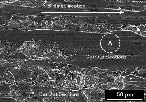
shows a general view of the examined part of a sliding surface of the tested transmission parts. The surface of the component was locally damaged by wear. Sections A and B were cut by a focused ion beam (FIB) FB-2100 system manufactured by Hitachi High-Technologies (Tanaka, et al. ( Citation 32 )) and examined by SEM and TEM in order to determine the metal structure underneath the sliding surface. The surface of section A was smooth and had no damage but that of section B was rough and showed damage. Very thin cross-sectional samples were prepared for TEM observation by sputtering the surrounding area with a gallium ion gun (Wang, et al. ( Citation 33 )).
Examination of the Metallic Crystalline Structure of Section A
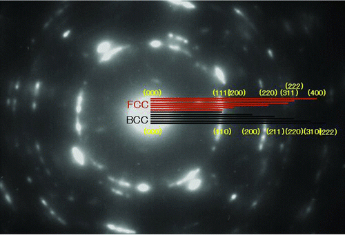
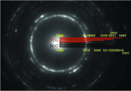
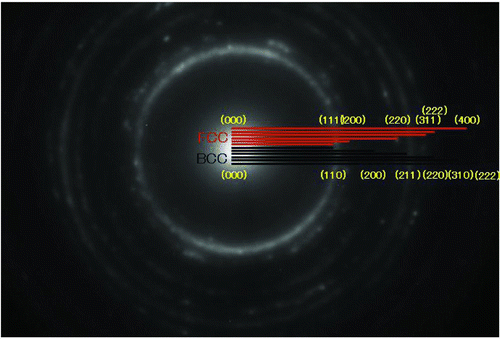
The FIB specimen of section A, which was rather smooth and had no damage on the sliding surface, was examined by TEM. The cross-sectional TEM images and the corresponding electron diffraction (ED) patterns of the material under the sliding surface are shown in . The position of the sliding surface is shown by a dotted line in . The sliding direction is shown by the arrow. From left to right, the depth increased, and the right end of the photo is about 6 μm deep.
Fig. 3 Dark-field images and the corresponding ED patterns of the crystal structure below the sliding surface.
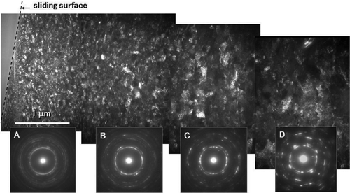
The TEM images show that the grain sizes were very fine in the subsurface area down to about 1 μm depth but they became large in proportion to the increase in depth, and grains of the original sizes remained at 6 μm depth.
shows the analysis of the ED pattern of the photo shown in . The ring spots of electron diffraction patterns appear at (110), (200), (211), (220), (310), (222), (321), (400), (330), (411), (420) in the case of BCC structure and at (111), (200), (220), (311), (222), (400), (331), (420), (422), (333), (511) in the case of the face-centered cubic (FCC) structure (Saka ( Citation 34 )). In addition to the ring spots of electron diffraction patterns, several signals can be seen in the case of BCC but no signal in the case of FCC. The ring spots of electron diffraction patterns of the specimens were examined on the basis of these data.
The ED patterns of , which are shown in , have ring spots at (110), (200), (211), (220), (310), and (222), and several signals can be seen inside the ring of (110), which shows that the original BCC structure (αFe) remains in the area of 5–6 μm depth from the sliding surface. Spots on the streak line of electron diffraction are clear. This suggests that crystallization is evident.
shows the analysis of the ED pattern of the photo shown in . The ED pattern shows both BCC with (110), (211), (220) and FCC with (111), (200), (220), (311), and (222), in addition to several unclear spots inside the ring of (110). These spots suggest that both a BCC crystalline structure and an FCC crystalline structure coexist in the area.
shows the analysis of the ED pattern of the photo shown in . The ED pattern shows FCC with (200), (220), (311), and (222), but there is no ED pattern at (110), (200), (211), (220), (310), and (222), which show BCC. In addition to the ring spots of FCC, there is no signal inside the ring of (200). This suggests that the crystalline structure of this area is FCC. Because halo rings are seen, it is considered that the crystalline structure transformed from BCC to FCC and that grains became fine in the range of 0.294−0.358 μm.
Examination of the Metallic Crystalline Structure of Section B
Cross-sectional TEM micrographs of section B of , which was rough with some damage on the sliding surface, are shown in . The part shown by a red square is enlarged and shown in the inset in the left side of the . The damaged surface had a crack. The magnified dark-field image indicates that the grain size just below the sliding surface was less than 0.01 μm. Dense dislocations remained in rather large grains. However, the crystalline structure was similar to that shown in .
Fig. 7 Cross-sectional TEM image just under the sliding surface of section B of (color figure available online).
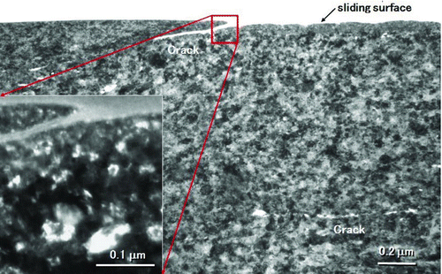
The photo in shows a crack nearly parallel to the sliding surface and several fine cracks at a depth of about 1 μm, although the crystalline structure of section A of , the surface of which was not damaged, did not have cracks such as those shown in . This may suggest that the force that caused damage to the surface affected the crystalline structure of the subsurface at about 1 μm depth. The fine cracks look almost connected by propagation, which may suggest that they will form a long crack over time. Then a fish scale–like thin wear particle can be exfoliated. It may be necessary to determine why such fine cracks were caused in the structure.
Crystalline Structure of Fe Alloys
The metallurgical theories are constructed on the basis of precisely controlled temperature and it is known that Fe base metals are ferrite having a BCC crystalline structure at room temperature and that ferrite transforms to austenite having an FCC crystalline structure when heated to 1185 K and higher under controlled condition. It is also known that austenite will reversely transform to ferrite when cooled to room temperature (Callister ( Citation 35 )). However, the ED analysis of the part of a transmission, which was tested in accordance with the actual driving model, showed an FCC crystalline structure as shown in , although the analysis was conducted at room temperature. Therefore, the facts that were found in this study might suggest that there were some unknown conditions that the standard metallurgical theories did not predict. Yoshizaki,, et al. ( Citation 5 ) examined the surface of gas-carburized transmission gear material (SCM-420) using X-ray diffraction and reported that the thickness of the nonmartensitic layer was 12–18 μm and the depth of intergranular oxidation was 14–18 μm, but they did not explain the details of the nonmartensitic layer and the intergranular oxidation. Therefore, there must be some possibility that the crystalline structure of the material of tested transmission parts may be different from that described by standard metallurgical theories, because high temperature and high pressure are applied to transmission parts (Toyota Motors ( Citation 36 )).
Evans, et al. ( Citation 8 ), ( Citation 9 ) examined boundary-lubricated tapered roller bearing inner ring (cone) surfaces by TEM and SEM and reported that the fine grains of the near-surface material were mostly ferrite (BCC) and martensite (body-centered tetragonal [BCT]) and that the materials at a depth exceeding 2 μm were martensite and austenite (FCC) (Evans, et al. ( Citation 8 ), ( Citation 9 )). The findings of Evans, et al. were different from ours. Therefore, further investigation was necessary.
Isochronal Annealing in TEM
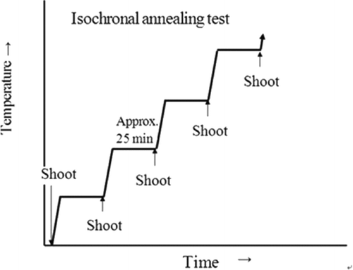
In order to determine the thermal stability of the microstructure, isochronal annealing (Tsukuda, et al. ( Citation 37 )) was performed in a TEM. The sample was heated from 373 to 873 K in steps of 100 K as schematically shown in . After holding for about 25 min at each temperature micrographs were taken and the temperature was raised to the next step.
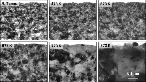
shows the microstructures at the same position near the sliding surface after annealing at each temperature denoted in the pictures. The microstructure at 473 K was almost similar to that at room temperature, whereas the microstructure at 573 K was slightly coarsened compared to that at 473 K and it became apparent above 673 K.
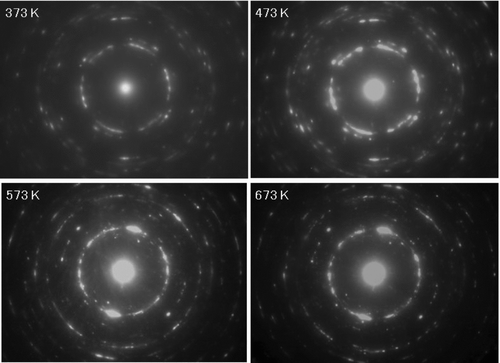
The magnified TEM images and the corresponding diffraction patterns at each annealing temperature are shown in . The detailed crystalline structure did not change at temperatures up to 473 K, whereas the fine stripe pattern, which can be seen clearly in a grain at the center at 373 K, disappeared at temperatures between 473 and 573 K. The diffraction rings at room temperature showed that the majority of the crystalline structure was FCC. However, the FCC crystalline structure began to decrease and the BCC structure began to increase at 473 K.
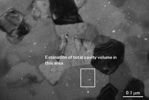
shows a TEM image after annealing at 873 K. Dislocations almost disappeared but a large number of cavities existed.
DISCUSSION
Evans, et al. ( Citation 8 ) reported that the crystalline structure in in their paper was BCC with ring spots at (110) and (211). We also examined the crystalline structure of used bearings. However, the ED examination of our tested continuously variable transmission (CVT) pulley exhibited an FCC structure at the near surface. We compared the difference between the two tests. The duration of the tests by Evans, et al. (i) was 7 days (168 h), whereas ours was 400 h. Evans, et al. ( Citation 8 ) tested roller bearing steels, whereas we tested SCM-420, which is used for CVT pulley and gears. Both materials had retained austenite. The loads for the tests were not substantially different. It is difficult to determine why the results of the ED examination of two tests were different from the comparison of the test materials and test conditions. We reviewed literatures that dealt with structural and texture transformation and found a paper by Ivanisenko et al. (38) which discussed transformation of BCC to FCC. They hypothesized that the adiabatic shear bands were formed when the strain rate was so high (>103 s-1) that the local heat generated could not escape from the deformation area, and that the austenite in the severe plastically deformed steel must have been formed via a reverse martensitic transformation. But as the pressure of our tests was not so high, this hypothesis cannot be applied to our case. Ivanisenko, et al. (38) observed in their experiment that supersaturated volume of carbon concentration were about 0.5–2 at %, which was much higher than room temperature solubility limit (0.15 at %) of carbon in ferrite (BCC). Since the solubility of carbon in austenite (FCC) is more than 20 times higher than that in ferrite, it is easily expected that excessive carbon atoms would diffuse in FCC area if their mobility is high enough. Therefore they hypothesized that grains of the tested steel were transformed to austenite grains. We share this hypothesis. Our hypothesis is that the crystal structure of BCC in the near surface area, the material of which was hardened by carbonitriding, became very fine by the repeated vibration and the shear stress and that the concentration of carbon atoms, which were extracted from the refined carbides, became higher than the solubility limit in BCC. Hence, the excessive carbon atoms were forced to dissolve in the crystal structure of the Fe alloy to transform to an FCC structure. Sauvage, et al. ( Citation 39 ) reported that the driving force and the kinetics of the phase transformation are still controversial. Therefore, we are now working to demonstrate the mechanism of the driving force that carbon atoms are forced into the crystalline structure of BCC to transform into FCC. We hope that we can find the mechanism in the near future.
The ED patterns in show that almost all of the FCC crystalline structure disappeared and the BCC crystalline structure became dominant at a temperature of 573 K. This may correspond to the fact that diffraction rings corresponding to FCC—for example, the second ring, which is (200) of FCC—become very weak at temperatures between 473 and 573 K. In addition, diffraction spots from fine grains of cementite became remarkable in the same temperature region. These facts indicate that temperature higher than 473 K cause transformation of the crystalline structure. Carbon atoms will start to precipitate in the FCC crystalline structure when the temperature exceeds 573 K. Therefore, the FCC structure will be transformed to BCC.
Many studies have been published on flash temperature, which is produced by metal-to-metal sliding or rubbing. Such temperature is variable depending on the load, sliding speed, materials, and lubricating conditions. The flash temperature is high without lubrication and low with lubrication. Transmissions are lubricated with oil. Reports on oil lubrication have reported measured contacting surface temperatures of over 873 K (Bowden and Ridler ( Citation 40 )), 403–493 K at a velocity of 200–400 mm/min (Blok ( Citation 41 )), 407–491 K using a two-disk machine with a disk of 2.4 in. diameter at 425 rpm with load of 230–560 lb (Fein ( Citation 42 )), maximum 633 K in tests using a steel ball and sapphire disc machine at a velocity of 1.39 m/s with a load of 1.04 × 10⁹ N/m2 (Turchina, et al. ( Citation 43 )), and 373–523 K at the center of medium rough rotating ball pressed to a sapphire disc with a load of 1.51–2.03 GN/m2 (Nagaraj, et al. ( Citation 44 )). Therefore, it can be said from the data of isochronal annealing in TEM and previous studies on the surface temperature of sliding parts under lubricated conditions that the transformation of the crystalline structure of the material of transmission parts would occur during operation of a transmission. The transmission will cool down when it stops. Therefore, the reverse transformation of the crystalline structure of the material of transmission parts will occur as it cools. It is considered that the precipitated carbon atoms will become a driving force to cause reverse transformation to FCC by sliding.
These results indicate that carbon atoms resolved in the FCC matrix as they became mobile in this temperature range and resulted in the formation of fine-grained cementite and transformation from BCC to FCC. Diffraction rings become sharper at temperatures higher than 573 K. This indicates an increase in grain size and a decrease in internal stress.
It was reported that thermodynamically stable cavities exist in the matrix of the material before annealing (Davies and Williams ( Citation 26 )). Cavities may have grown by annealing at 973 K. This may be why a large number of cavities are seen in the TEM image after annealing at 873 K, as shown in . Therefore, it is important to know how such cavities are formed in the matrix. It is known that the transformation from ferrous austenite to martensite increases the volume. Moyer and Ansell ( Citation 27 ) confirmed that the increase in volume by the transformation from austenite to martensite was about 2.0 to 3.1%. Therefore, the inverse transformation from BCC to FCC will reduce the volume. On the assumption that a cavity is a ball, the fraction (ΔV/V) of cavities was estimated to be 2.7% by measuring the size of each cavity. The calculated total volume of the cavity was very close to the volume of the change due to transformation measured by Moyer and Ansell ( Citation 27 ). Therefore, it may be considered that cavities and their small clusters are formed by the inverse transformation from BCC to FCC to compensate for volume shrinkage. In the case that abundant cavities are formed by phase transformation from BCC to FCC in front of crack tips, the propagation of cracks will be enhanced and thin wear particles with a fish scale–like shape will come off. It can be considered that the process may produce delamination wear.
SUMMARY AND CONCLUSION
| 1. | The wear of chrome molybdenum steel (SCM-420) having molybdenum in the range of 0.15% to 0.30% chrome steel used in a transmission was investigated using SEM and TEM. | ||||
| 2. | The material from the sliding surface to the area about 1 μm deep showed an FCC structure, although a BCC structure dominated in the area down to 6 μm deep. | ||||
| 3. | When the inverse transformation from BCC to FCC occurred in the area about 1 μm deep from the sliding surface, the volume of the material was reduced and a small cavity was formed to compensate for the reduction in volume. | ||||
| 4. | The propagation of the cavity may be considered to be the mechanism of the delamination of fish scale–like thin wear particles. | ||||
Acknowledgments
Review led by Vasilios Bakolas
REFERENCES
- Fereimanis , A. J. , Segall , A. E. , Conway , J. C. Jr. and Whitney , E. J. 2002 . The Influence of Temperature on the Wear Mode and Deterioration of Coating Used for Titanium Engine Components . Tribology Transactions , 45 ( 2 ) : 193 – 198 .
- Wong , H. , Liou , J. , Wu , C. , Chang , S. and Ku , C. 2002 . Bench Test Evaluation of Thermal Stability and Lubricity of Anti-Wear Hydraulic Oils in an Acid Atmosphere . Tribology Transactions , 45 ( 2 ) : 217 – 222 .
- Yoon , H. , Zhang , J. and Kelley , F. 2002 . Scuffing Characteristics of SAE 50B38 Steel under Lubricated Conditions . Tribology Transactions , 45 ( 2 ) : 246 – 252 .
- Kovalchenko , A. , Gogotsi , Y. , Domnich , V. and Erdemir , A. 2002 . Phase Transformations in Silicon under Dry and Lubricated Sliding . Tribology Transactions , 45 ( 3 ) : 372 – 380 .
- Yoshizaki , M. , Hashimoto , T. and Kasamatsu , C. 2003 . Effect of Abnormal Surface Layer on Tooth Surface Strength Increase of Gas Carburized Gears . Tribology Transactions , 46 ( 1 ) : 83 – 94 .
- Oyamada , T. and Inoue , Y. 2003 . Evaluation of the Wear Process of Cast Iron Coated with Manganese Phosphate . Tribology Transactions , 46 ( 1 ) : 95 – 100 .
- Zhang , C. , Cheng , H. S. and Wang , O. J. 2004 . Scuffing Behavior of Piston-Pin/Bore Bearing in Mixed Lubrication—Part II: Scuffing Mechanism and Failure Criterion . Tribology Transactions , 47 : 149 – 156 .
- Evans , R. , More , K. L. , Darragh , C. V. and Nixon , H. P. 2004 . Transmission Electron Microscopy of Boundary-Lubricated Bearing Surface Part I: Mineral Oil Lubricant . Tribology Transactions , 47 : 430 – 435 .
- Evans , R. , More , K. L. , Darragh , C. V. and Nixon , H. P. 2005 . Transmission Electron Microscopy of Boundary-Lubricated Bearing Surface Part II: Mineral Oil Lubricant with Sulfur- and Phosphorous-Containing Gear Oil Additives . Tribology Transactions , 48 : 299 – 307 .
- Warren , A. W. and Guo , Y. B. 2005 . Numerical Investigation on the Effects of Machining-Induced White Layer during Rolling Contact . Tribology Transactions , 48 : 436 – 441 .
- Ito , K. , Martin , J. M. , Mimfray , C. and Kato , K. 2007 . Formation Mechanism of a Low Friction ZDDP Tribofilm on Iron Oxide . Tribology Transactions , 50 : 211 – 216 .
- Rahman , M. Z. , Ohba , H. , Yamamoto , T. and Yoshioka , T. 2008 . A Study on Incipient Damage Monitoring in Rolling Contact Fatigue Process Using Acoustic Emission . Tribology Transactions , 51 : 543 – 551 .
- Lin , P. , Barber , G. , Zou , Q. , Anderson , A. H. Jr. , Tung , S. and Quintana , A. 2008 . Friction and Wear of Low-Phosphorous Engine Oils with Additional Molybdenum and Boron Compounds Measured on a Reciprocating Lubricant Tester . Tribology Transactions , 51 : 659 – 672 .
- Liew , W. 2009 . Experimental Study on the Performance of Coated Carbide Tools in the Ultra-Precision Machining of Stainless Steel . Tribology Transactions , 52 : 293 – 302 .
- Goto , H. , Suciu , C. V. and Inokuchi , T. 2009 . Friction and Wear Properties of Aluminum–Silicon Alloy Impregnated Graphite Composite (ALGR-MMC) under Lubricated Sliding Conditions . Tribology Transactions , 52 : 331 – 345 .
- Toparli , M. , Celik , E. , Birlik , I. , Dokumaci , E. and Ak Azem , N. F. 2009 . Tribological Properties of Electric Arc-Sprayed CuSn Coating for Bearing Elements . Tribology Transactions , 52 : 389 – 394 .
- Rasoda , L. , Forster , N. H. , Thompson , K. L. and Kooke , J. W. 2010 . Rolling Contact Fatigue Life and Spall Propagation of AISI M50, M50NiL, and AISI 5210, Part I: Experimental Results . Tribology Transactions , 53 : 29 – 41 .
- Guo , Y. B. and Walker , R. A. 2010 . An Experimental Study on the Effect of Machining-Induced White Layer on Frictional and Wear Performance at Dry and Lubricated Sliding Contact . Tribology Transactions , 53 : 127 – 136 .
- Cho , D. H. , Lee , S. A. and Lee , Y. Z. 2010 . The Effects of Surface Roughness and Coatings on the Tribological Behavior of the Surfaces of a Piston Skirt . Tribology Transactions , 53 : 137 – 144 .
- Leonard , B. D. , Sadeghi , F. , Evans , R. D. , Doll , G. L. and Shiller , P. J. 2010 . Fretting of WC/s-C:H and Cr2N Coatings under Grease-Lubricated and Unlubricated Conditions . Tribology Transactions , 53 : 145 – 153 .
- Li , J. , Xiong , D. , Wu , H. , Huang , Z. , Dai , J. and Tyagi , R. 2010 . Tribological Properties of Laser Surface Texturing and Molybdenizing Duplex-Treated Ni-Base Alloy . Tribology Transactions , 53 : 195 – 202 .
- Wei , W. , Xiaojun , L. , Kun , L. and Hongxian , L. 2010 . Experimental Study on the Tribological Properties of Powder Lubrication under Plane Contact . Tribology Transactions , 53 : 274 – 279 .
- Suh , N. P. 1977 . An Overview of the Delamination Theory of Wear . Wear , 44 : 1 – 16 .
- Flaming , J. R. and Suh , N. P. 1977 . Mechanics of Crack Propagation in Delamination Wear . Wear , 44 : 39 – 56 .
- Flaming , J. R. and Suh , N. P. 1977 . The Relationship between Crack Propagation Rates and Wear Rates . Wear , 44 : 57 – 64 .
- Davies , P. W. and Williams , K. R. 1968 . The Effects of Grain Boundary Cavities on Vacancy Diffusion . Philosophical Magazine , 18 : 137 – 143 .
- Moyer , J. M. and Ansell , G. S. 1975 . The Volume Expansion Accompanying the Martensite Transformation in Iron–Carbon Alloy . Metallurgical Transactions A , 6 : 1785 – 1791 .
- Argon , A. S. , Im , J. and Safoglu , R. 1975 . Cavity Formation from Inclusions in Ductile Fracture . Metallurgical Transactions A , 6 : 825 – 837 .
- Jahanmir , S. and Suh , N. P. 1977 . Mechanics and Subsurface Void Nucleation in Delamination Wear . Wear , 44 : 17 – 38 .
- Calcagnotto , M. , Adachi , Y. , Ponge , D. and Raabe , D. 2011 . Deformation and Fracture Mechanisms in Fine- and Ultrafine-Grained Ferrite/Martensite Dual-Phase Steels and the Effect of Aging . Acta Materialia , 59 : 658 – 670 .
- Kanazawa , K. , Yamaguchi , K. , Sato , M. and Kanao , M. 1980 . High-Temperature, High-Cycle Fatigue Properties of S45C and SCM435 Steels . The Society of Materials Science, Japan , 30 ( 332 ) : 454 – 460 .
- Tanaka , T. , Fujiwara , M. and Shimizu , I. 2006 . Micrometer-Scale Fabrication and Assembly Using Focused Ion Beam . Thin Solid Films , 509 : 113 – 117 .
- Wang , Z. , Kato , T. , Hirayama , T. , Kato , N. , Sasaki , K. and Saka , H. 2005 . Surface Damage Induced by Focused-Ion-Beam Milling in a Si/Si p-n Junction Cross-Sectional Specimen . Applied Surface Science , 241 : 80 – 86 .
- Saka , H. 2005 . Crystal Electron Microscopy , Tokyo, Japan; Uchida Rokkakuho . in Japanese
- Callister , W. D. Jr. 2011 . Materials Science and Engineering—An Introduction , Tokyo, Japan; Baifukan Publishing Co., Ltd. . in Japanese
- Toyota Motors . Patent No. 2006–206938. “Method for Manufacturing Machine Parts.”
- Tsukuda , N. , Kuramoto , E. , Aono , Y. , Kitajima , K. , Abe , H. , Yoshida , N. , Akashi , Y. , Takenaka , M. , Mitarai , S. and Isoya , A. 1985 . Application of a High Energy Tandem Accelerator to the Study of Radiation Damage Effects on Stainless Steels . Journal of Nuclear Materials , 133–144 : 873 – 877 .
- Ivanisenko , Y. , McLaren , I. , Sauvage , X. , Valiev , R. Z. and Fecht , H.-J. 2006 . Sheared-Induced α → γ Transformation in Nanoscale Fe-C Composite . Acta Materialia , 54 ( 6 ) : 1659 – 1669 .
- Sauvage , X. , Lefebvre , W. , Genevois , C. , Ohsaki , S. and Hono , K. 2009 . Complementary Use of TEM and APT for the Investigation of Steels Nanostructured by Severe Plastic Deformation . Scripta Materialia , 60 : 1056 – 1061 .
- Bowden , F. P. and Ridler , K. E. W. 1936 . Physical Properties of Surfaces III—The Surface Temperature of Sliding Metals, the Temperature of Lubricated Surfaces . Proceedings of the Royal Society of London A , 154 : 640 – 656 .
- Blok , H. 1963 . The Flash Temperature Concept . Wear , 6 : 483 – 494 .
- Fein , R. S. 1967 . Operating Procedure Effects on Critical temperatures . ASLE Transactions , 10 : 373 – 385 .
- Turchina , V. , Sanborn , D. M. and Winer , W. O. 1974 . Temperature Measurements in Sliding Elastohydrodynamic Point Contact, . Journal of Lubrication Technology , 96 ( 3 ) : 464 – 471 .
- Nagaraj , H. S. , Sanborn , D. M. and Winer , W. O. 1977 . Effects of Load, Speed, and Surface Roughness on Sliding EHD Contact Temperatures . Journal of Lubrication Technology , 99 ( 2 ) : 254 – 263 .
