
 ?Mathematical formulae have been encoded as MathML and are displayed in this HTML version using MathJax in order to improve their display. Uncheck the box to turn MathJax off. This feature requires Javascript. Click on a formula to zoom.
Abstract
Recently, concentrated polymer brushes (CPBs) have attracted much attention as potential tribomaterials showing an ultralow friction coefficient (e.g., 10−4 in a microtribological analysis). In this study, a homemade apparatus modeling reciprocating seals was developed, which consisted of an inner steel rod and an outer steel ring with a narrow clearance less than several tens of micrometers. A few-micrometer-thick CPB film of poly(methyl methacrylate) well-swollen with an ionic liquid was prepared on each steel surface, and the impact of applying the CPB film to the clearance of reciprocating seals was examined by measuring the leakage rate of a fluid and the friction coefficient in reciprocating motion. The results showed that the CPB film narrowed the clearance between the two steel surfaces, which improved its sealing performance. In addition, the CPB film yielded a quite low friction coefficient (e.g., 10−3), which assured its smooth motion with small energy loss.
Introduction
Sealing technologies are indispensable in modern machines (Horve (Citation1); Flitney (Citation2)). For example, it is well known that more than one hundred seals are installed in a standard automobile powered by an internal combustion engine. Seals are classified as static seals and dynamic seals, where the former operates in a situation with no relative motion of two surfaces, whereas the latter operates in a situation with relative motion of two surfaces. In addition, according to the difference in the direction of relative motion, dynamic seals are classified a rotary seals and reciprocating seals. Reciprocating seals are typically applied in piston-and-cylinder systems; for example, reciprocating engines (Enomoto and Yamamoto (Citation3); Tung and McMillan (Citation4)), reciprocating compressors (Bloch and Hoefner (Citation5)), and pneumatic cylinders (Rapareli, et al. (Citation6)). Other applications include vane-and-slot systems in rotary compressors (Mi and Meng (Citation7)) and plunger-and-bore systems in high-pressure-type pumps.
The primary concept of reciprocating seals is to narrow the clearance between two surfaces in relative motion. A narrower clearance provides lower leakage of fluids that are supposed to be sealed, but a narrower clearance also tends to cause higher friction by direct contact between the surfaces, leading to stick–slip vibrations or scuffing. On the other hand, a wider clearance might provide lower friction, leading to smooth motion with smaller energy loss, but a wider clearance might cause not only higher leakage of the fluids but also unexpected pitching vibrations due to excess clearance.
A solution for the above dilemma is adding another component, seal rings, to the clearance. For example, piston rings made of heat-stable materials are installed in piston-and-cylinder systems in internal combustion engines in automobiles. In addition, to achieve lower friction and smaller energy loss, hard coatings such as diamond-like carbon coatings are applied (Wang and Tung (Citation8); Merlo (Citation9); Tung and Gao (Citation10); Podgornik and Vižintin (Citation11)). When seal rings are not applicable, only hard coatings are applied to narrow clearance to reduce friction, such as in vane-and-slot systems in rotary compressors (Sung (Citation12); Huang and Gao (Citation13)). That is, with or without seal rings, applying harder materials and harder coatings is the current trend in reciprocating seals.
However, the above trend does not necessary preclude using soft materials and soft coatings in reciprocating seals. Although soft materials often exhibit high friction, seal rings made of rubber are practically used, for example, in medical syringes. This is because to achieve high sealing performances, the rich elasticity of soft materials is quite useful. In addition, compared to hard materials, the rich elasticity of soft materials is expected to lower aggressivity between mating surfaces. Therefore, a soft material with ultralow friction is a potential tribomaterial for reciprocating seals. If the material is applicable as a soft film, it provides the potential for ideal reciprocating seals with no seal rings. This study focused on a concentrated polymer brush (CPB) as a potential soft tribocoating.
A polymer brush is an assembly of polymer chains densely end-grafted on a solid surface (Napper (Citation14); Parnas and Cohen (Citation15); Klein and Kumacheva (Citation16); Klein (Citation17)). Surface-initiated living radical polymerization (Edmondson, et al. (Citation18); Tsujii, et al. (Citation19); Barbey, et al. (Citation20)) has recently afforded an exceptional increase in the graft density more than one order of magnitude higher than that of typical semidilute polymer brushes (Ejaz, et al. (Citation21)). Such high-density polymer brushes reasonably fall in the regime of the concentrated state, or CPB.
Regarding the frictional properties of CPBs, microtribological analysis using atomic force microscopy (AFM) revealed that in a good solvent (toluene), CPBs of poly(methyl methacrylate) (PMMA) exhibit ultralow friction with an extremely low friction coefficient (e.g., 10−4; Tsujii, et al. (Citation22)). Surface-initiated living radical polymerization under high pressure provides an exceptional increase in thickness more than one order of magnitude greater than that of conventional CPBs. An increase in thickness is effective for improving durability under sliding contact (Belin, et al. (Citation23)) and thus could make it applicable to mechanical components, such as journal bearings, sealing devices, and piston assemblies.
In this study, to examine the impact of applying a thick CPB film well-swollen by an ionic liquid to the clearance of reciprocating seals, the leakage rate and the friction coefficient were measured using a homemade apparatus consisting of an inner rod and an outer ring. The results showed that the CPB film narrowed the clearance between the two surfaces, which improved its sealing performance. In addition, the CPB film yielded a quite low friction coefficient (e.g., 10−3), which assured its smooth motion with small energy loss.
Experimental details
Test materials
Materials
Steel rods (material: AISI 52100 steel, diameter (2r1): 9.920–9.990 mm, length: 50 mm, arithmetic average roughness: 10 nm) and steel rings (material: AISI 52100 steel, inner diameter (2r2): 10.000 mm, thickness: 10 mm, arithmetic average roughness: 10 nm) were used as test specimens. A silicon substrate (one side chemically and mechanically polished, 525 μm thick) was used as a reference specimen. To prepare for synthesis of the PMMA-CPBs, the substrates were cleaned by ultrasonic treatment in acetone–hexane (1:1, v/v), chloroform, and 2-propanol for 30 min each and treated with a UV–ozone cleaner for 30 min just before use. Methyl methacrylate was passed through natural alumina to remove any radical inhibitors prior to use. (2-Bromoisobutyryloxy)propyltrimethoxysilane was immobilized on the steel rods, steel rings, and silicon substrate as an initiator for graft polymerization according to a method reported previously (Ohno, et al. (Citation24)). 4,4′-Dinonyl-2,2′-bipyridine was used as received. N,N-Diethyl-N-methyl-N-(2-methoxyethyl)ammonium bis(trifluoromethane sulfonyl)imide (DEME-TFSI) was used as a solvent for swelling the CPB and as a lubricant.
Synthesis of PMMA–CPB on a steel substrate
Sample preparation was performed under an argon atmosphere using glove boxes. The (2-bromoisobutyryloxy)propyltrimethoxysilane-immobilized steel rods, steel rings, and silicon substrate were placed in a fluoroplastic vessel containing a solution of methyl methacrylate (29.0 g, 4.7 M), copper (I) bromide (0.132 g, 0.015 M), copper (II) bromide (0.0279 g, 0.0020 M), and 4,4′-dinonyl-2,2′-bipyridine (0.937 g, 0.038 M) in anisole (30.00 g). The vessel was tightly closed, covered with an aluminum bag to prevent oxygen contamination, and placed in a high-pressure reaction device equipped with a high-pressure vessel, an automated high-pressure pump using water as a pressure medium, and a circulating thermostatic bath. Polymerization was conducted at 60 °C and 400 MPa for 16 h. After polymerization, the CPB-grafted steel samples were washed with tetrahydrofuran (THF) several times in a shaking apparatus. The average dry thickness (Ldry) of the PMMA-CPBs on the steel rods and steel rings was determined to be 1.8 μm using an ellipsometer.
Characterization of graft PMMA
The PMMA graft polymers on the silicon substrate synthesized under the same conditions described above were isolated by a so-called cutoff experiment. The silicon substrate grafted with PMMA was placed in a hydrofluoric acid solution (10%) for 3 days, yielding a detached floating graft polymer layer. The layer was removed, dissolved in THF, and subjected to gel permeation chromatography analysis, which was performed at 40 °C on a high-speed liquid chromatography system equipped with a guard column, two 30-cm mixed columns (exclusion limit = 2 × 10⁷), and a differential refractometer. THF was used as an eluent at a flow rate of 0.8 ml/min. The number average molecular weight (Mn) and polydispersity index were estimated by calibration using prepared PMMA standards (Mp = 1.31 × 10³–1.64 × 10⁶), and the estimate was complemented by calibration using polystyrene standards (Mp = 1.93 × 10³ –1.32 × 10⁷). Mn and the polydispersity index were evaluated to be 4.0 × 10⁶ and 1.53, respectively. The graft density σ was calculated to be 0.34 chains/nm2 from Ldry, Mn, and the density (ρ) of bulk PMMA (1.19 g/cm3) using the following equation: σ = ρLdryNA/Mn, where NA is the Avogadro constant. The surface occupancy (σ*) of the PMMA brush was calculated to be 0.19 using the value σ and the cross-sectional area (a2) using the following equation: σ* = a2σ, where the cross-section area of PMMA is 0.554 nm2 (Yamamoto, et al. (Citation25)). Using the criteria of CPBs based on the scaling theory (Tsujii, et al. (Citation19)), the PMMA brushes prepared in this study were categorized to be in the regime of CPB.
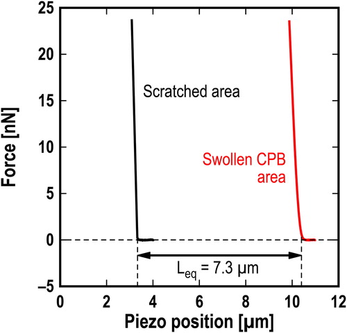
Force curve measurements of the PMMA-CPB (Ldry = 1.9 μm) on the silicon substrate in DEME-TFSI were performed by AFM after the CPB was swollen by immersion in DEME-TFSI for 24 h. A rectangular cantilever (kn = 0.1 N/m) with a silica particle (diameter: 10 μm) was used. The force curves at the scratched and swollen CPB area were obtained at an approach speed of 1.0 μm/s as shown in . The equilibrium thickness (Leq) of the swollen CPB was estimated from the difference of the piezo position at 0.1 nN between the scratched and swollen CPB areas. The equilibrium thickness Leq was 7.3 μm. The swelling ratio Leq/Ldry was 3.8, where Ldry = 1.9 μm.
Figure 1. Representative force curves at scratched area (black) and swollen CPB area (red) in DEME-TFSI.
Leakage rate measurements
Principle
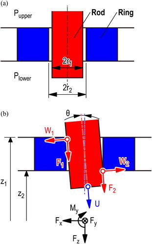
shows the configurations for measuring the leakage rate of fluid through a narrow gap between an inner rod and an outer ring. The liquid is pooled in a reservoir above the narrow gap. When the air pressure Plower in the lower space below the narrow gap is lower than the air pressure, Pupper, in the reservoir (Pdiff = Pupper − Plower > 0, where Pdiff is the differential pressure between the upper and lower spaces), the liquid leaks from the reservoir to the lower space through the narrow gap. When the lower space is closed except for the narrow gap, the leakage of the liquid causes changes not only in the air volume V of the lower space but also in the air pressure P of the lower space, where the air volume is the same as the space volume of the lower space before leakage. Assuming that the leakage of the liquid isothermally changes V and P without vaporizing the leaked liquid, the changes are written as follows:
[1]
[1]
where P0 and V0 are the initial value of P and V, respectively, and ΔP and ΔV are the increase in P and decrease in V, respectively. When ΔP/P0 ≪ 1, the leakage rate Q of the liquid is obtained as follows:
[2]
[2]
where EquationEq. [2]
[2]
[2] is reliable when ΔP/Pdiff ≪ 1 because the leakage rate of the liquid is proportional to Pdiff.
Figure 2. Configurations for measuring (a) leakage rate and (b) friction coefficient of reciprocating seal consisting of inner rod and outer ring.
Apparatus
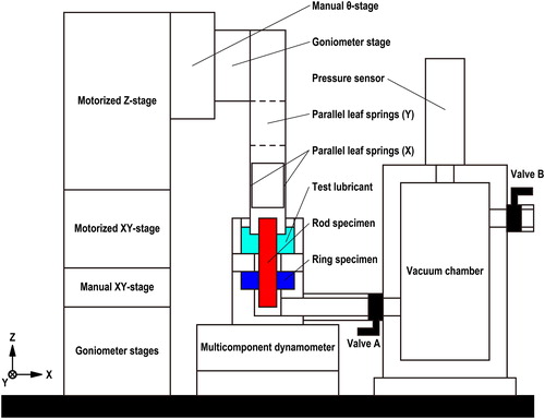
and show a photograph and a schematic diagram, respectively, of the apparatus for measuring the leakage rate in a reciprocating seal, which consists of an inner steel rod and an outer steel ring. The rod is supported by two pairs of parallel leaf springs whose degrees of freedom are along the X and Y axes, as shown in . The parallel leaf springs are mounted on a stage unit, which consists of XYZ-axis motorized stages, XY-axis manual stages, and three rotational-axis manual stages to adjust the position and angle of the rod’s center axis against the ring’s center axis. The ring is fixed by an upper holder and a lower holder. The upper holder has space to reserve a test lubricant. The lower holder is mounted on a six-axis dynamometer and is connected to a vacuum chamber through a rubber tube and a valve (valve A). A vacuum pump is connected to the vacuum chamber through another valve (valve B). A pressure sensor is installed in the vacuum chamber to measure the air pressure in the lower space.
Figure 3. Photograph of apparatus for measuring the leakage rate and friction coefficient.
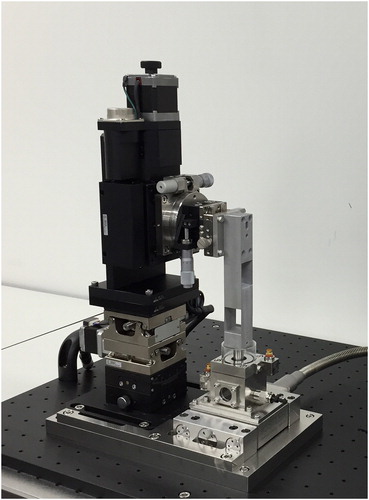
Figure 4. Schematic diagram of apparatus for measuring the leakage rate and friction coefficient.
Procedure
The rod and ring with the CPB film were cleaned thoroughly in THF and then hexane using an ultrasonic cleaner, dried in a stream of hot air, and swollen by immersion in DEME-TFSI for 24 h. The rod and ring without a CPB film were cleaned in acetone and then in hexane using an ultrasonic cleaner and dried. After the rod and ring were installed in the apparatus, the position and angle between the center axes of the rod and the ring were adjusted by the stage unit. The bottom of the rod was placed 5 mm below the bottom of the ring by the Z-axis motorized stage. With valve A closed, the air pressure in the vacuum chamber was decreased at P < 51 kPa (Pdiff > 50 kPa). After valve B between the vacuum chamber and the vacuum pump was closed, the vacuum pump was stopped. Then 440 mm3 of DEME-TFSI was pooled as a test liquid in the upper space above the narrow gap between the rod and the ring. When the lower space was connected to the vacuum chamber by opening valve A, the air pressure in the lower space was decreased to P = 51 kPa (Pdiff = 50 kPa) and was measured until P = 101 kPa (Pdiff = 0 kPa) without rubbing the rod and ring. The vapor pressure of ionic liquids such as DEME-TFSI is almost zero, which is a sufficiently small value for Pdiff. Hence, the change in P due to the vaporization of the leaked DEME-TFSI was negligible. The leakage rate was calculated by using EquationEq. [2][2]
[2] based on the experimentally measured dP/dt value, where the initial volume V0 in the lower space, including the rubber tube and vacuum chamber, was 3.1 × 104 mm3. The ambient temperature and relative humidity range were 25 °C and 20–40%, respectively. A pretest was performed using a no-hole specimen instead of the ring to check the unexpected leakage. The pretest showed that no leakage was detected for 100 h.
Friction coefficient measurements
Principle
shows the configurations for measuring the friction coefficient of the reciprocating seal under partial contacts between the inner rod and outer ring, where the axis of the rod is tilted by the angle θ. The normal loads W1 and W2 are applied at the partial contacts of the upper and lower edges of the ring, respectively. When the rod moves in the z direction at a constant speed U, the friction forces F1 and F2 are generated at the partial contacts. Assuming that the friction coefficient µ is constant during the sliding motion, the equations of balance are written as follows:
[3]
[3]
[4]
[4]
[5]
[5]
where Fx and Fz are the translational forces in the x and z directions, respectively, and My is the moment about the y direction. When θ is sufficiently small, EquationEqs. [3]–[5]
[3]
[3] can be rewritten as follows:
[6]
[6]
[7]
[7]
[8]
[8]
From EquationEqs. [6]–[8][6]
[6] , we obtain
[9]
[9]
Further, when µ is sufficiently smaller than unity, we obtain the following simple form:
[10]
[10]
Therefore, we can determine the value of µ using EquationEq. [9][9]
[9] or Equation[10]
[10]
[10] with the measured values of Fx, Fz, and My.
Apparatus
The same apparatus used to measure the leakage rate was used to measure the friction coefficient in the reciprocating seal. When the rod is loaded onto the ring using the x-axis motorized stage through the parallel leaf springs, the rod and ring are in contact at the partial contacts of the upper and lower edges of the ring. As the rod is moved in a reciprocating manner by the z-axis motorized stage, the three-axis translational forces and three-axis moments are measured by the dynamometer. In addition, the position of the z-axis motorized stage is monitored by a laser sensor.
Procedure
The rod and ring with the CPB film were cleaned thoroughly in THF and then hexane using an ultrasonic cleaner, dried in a stream of hot air, and swelled by immersion in DEME-TFSI for 24 h. Further, the rod and ring without the CPB film were cleaned in acetone and then in hexane using an ultrasonic cleaner and dried. After the rod and ring were installed in the apparatus, the rod was pushed to the ring at Fx = 5 N. With no decrease in the atmospheric pressure of the lower space, when the rod was reciprocated using the z-axis motorized stage at V = 1 mm/s and 10 mm/stroke, the values of Fx, Fz, and My were measured by the dynamometer. The measurement results for 100 reciprocation cycles were used to calculate the friction coefficient using EquationEq. [10][10]
[10] . The ambient temperature and relative humidity range were 25 °C and 20–40%, respectively.
Results
Leakage rate measurements
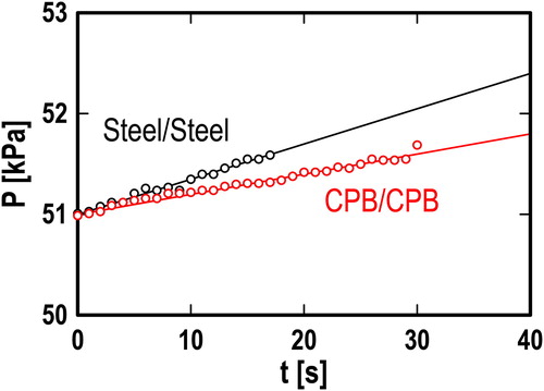
illustrates the change in the air pressure P in the lower space with time t for the rod and ring without the CPB (steel–steel) and with the CPB (CPB–CPB) at a radial gap h of 40 µm and Pdiff = 50 kPa. The black and red lines are linear fitting curves for steel–steel and CPB–CPB, respectively. The initial value of P for both steel–steel and CPB–CPB was P0 = 51 kPa, and P increased linearly with time in both cases along each fitting curve until P ≈ 51.7 kPa. ΔP = 0.7 kPa was converted to ΔV = 420 mm3 using Eq. [1], which is the leaked volume of DEME-TFSI. This suggests that almost all of the pooled DEME-TFSI (volume 440 mm3) leaked. When P > 51.7 kPa, it increased dramatically over the vertical axis range of the figure. This indicates that air started to leak through the narrow gap from the upper space to the lower space before all of the pooled DEME-TFSI leaked. This suggests that ΔV < 20 mm3 of DEME-TFSI remained in the upper space or the narrow gap by surface tension and that the air present formed a localized path in the narrow gap. The slope of P for CPB–CPB (dP/dt = 0.020 kPa/s, R2 = 0.98) was lower than that of steel–steel (dP/dt = 0.035 kPa/s, R2 = 0.98). The difference between the slopes for CPB–CPB and steel–steel shows that the leakage rate for CPB–CPB was lower than that for steel–steel.
Figure 5. Changes in pressure P with time t; h = 40 µm; Pdiff = 50 kPa.
shows the results of the leakage rate measurements, which reveal the effect of the radial gap h (= r2 − r1) between the rod and ring on the leakage rate Q for steel–steel and CPB–CPB, where the value of Q was calculated using Eq. [2] and the measured value of dP/dt. The black and red circles represent the results for steel–steel and CPB–CPB, respectively. The straight black line represents the theoretical volume flow per unit time through the narrow gap, which is given by the following equation for the Poiseuille flow in a cylindrical annulus (Bird, et al. (Citation26)):
[11]
[11]
where a is a constant. The dashed blue lines represent theoretical isothickness curves given by
[12]
[12]
where b is the total thickness of the effective films of the CPB for sealing on the surfaces of the rod and ring. When the surfaces of both the rod and ring are coated by the CPB with the same film thickness, b corresponds to 2Leff, where Leff is the effective film thickness of the CPB for sealing.
Figure 6. Effect of radial gap h on leakage rate Q.
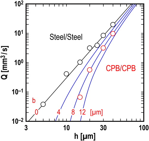
For steel–steel, Q appears to change along the straight black line, where a = 3.0 × 10⁵ s−1 (as determined by the least squares method for steel–steel). The results for steel–steel show that the setting between the rod and the ring in every test basically corresponded to the cylindrical annulus, which was assumed by EquationEq. [11][11]
[11] (Chen and Jackson (Citation27)). For CPB–CPB, Q appears to deviate downward from the straight black line and to change approximately along the dashed blue line for b = 8 µm. The results show that the swollen CPB on the surfaces of the rod and ring, which has an effective film thickness of Leff = 4 µm, narrowed the clearance between the rod and ring and prevented leakage of the test liquid.
Friction coefficient measurements
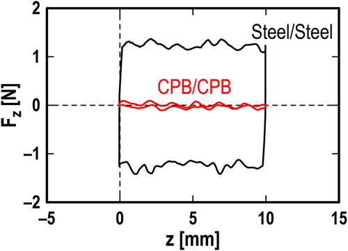
illustrates the measurement results for Fz for steel–steel and CPB–CPB at a radial gap h of 40 µm, which were obtained during back-and-forth motion of the rod. The value of Fz for CPB–CPB was more than 1 N smaller than that for steel–steel. The values of Fx (= 5 N) for both steel–steel and CPB–CPB did not change with the reciprocation. The value of My for both steel–steel and CPB–CPB was −0.19 Nm and also did not change with the reciprocation.
Figure 7. Changes in tangential force Fz against vertical position z in reciprocating motion; h = 40 µm; W = 5 N; V = 1 mm/s.
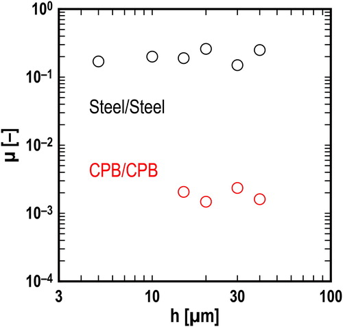
illustrates the results of the friction coefficient measurements, which reveal the effect of the radial gap h between the rod and ring on the friction coefficient µ for steel–steel and CPB–CPB, where the value of µ was calculated using EquationEq. [10][10]
[10] and the values of Fx, Fz, and My. The value of µ for steel–steel was 0.2 and was not dependent on h in the range h = 5–40 µm. The value of µ for CPB–CPB was 0.002 and was not dependent on h in the range h = 15–40 µm.
Figure 8. Effect of radial gap h on mean friction coefficient μ.
Discussion
Effective thickness of swollen CPB for sealing performance
The film thickness of the CPB was measured by three methods: ellipsometry, colloidal probe AFM, and leakage measurements in the apparatus. The film thicknesses Ldry of the dry CPB on the steel specimens and the silicon substrate, as measured by ellipsometry, were 1.8 and 1.9 µm, respectively. The equilibrium film thickness Leq of the swollen CPB on the silicon substrate, as measured by AFM with the colloidal probe, was 7.3 µm. Leq was 3.8 times Ldry (i.e., Leq/Ldry = 3.8). A result of Leq/Ldry > 3 for a CPB was obtained by Yamamoto, et al. (Citation26), although they investigated a thin CPB with Ldry ∼ 100 nm rather than a thick CPB. The effective film thickness Leff of the swollen CPB used for sealing the test liquid was measured based on leakage in the apparatus as 4 µm. Leff was 2.2 times Ldry (i.e., Leff/Ldry = 2.2). The effective film thickness of Leff = 4 µm out of the equilibrium film thickness of Leq = 7.3 µm (i.e., Leff/Leq = 0.55) had the effect of preventing leakage flow. This indicates that the CPB coated onto the surfaces of the clearance could effectively narrow the clearance.
Impact of CPB coating on reciprocating seal
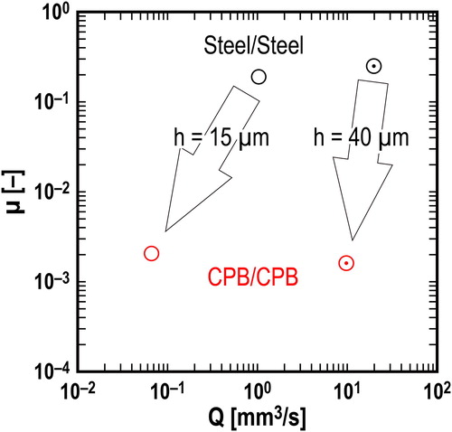
summarizes the impact of the CPB coating on the reciprocating seal. The vertical and horizontal axes represent µ and Q, respectively. Lower values of µ and Q mean better performance of the reciprocating seals. For h = 40 µm, the µ value of CPB–CPB was 1/50th that of steel–steel, but the Q value of CPB–CPB was only half that for steel–steel. For h = 15 µm, the µ values of CPB–CPB and steel–steel were not dependent on h. On the other hand, the Q value of CPB–CPB was 1/10th that for steel–steel. This was because the effective thickness was 8 µm, so the clearance was narrowed by 50% by the CPB coating.
Figure 9. Low leakage with low friction provided by the CPB film on a steel surface.
In fact, to narrow the radial clearance to less than 10 µm, a high-precision machine and great skill are necessary (Matsuura and Shinozaki (Citation28)). However, the application of CPB can provide a radial clearance of less than 10 µm without either. Applying a CPB coating could be an effective technique to narrow the clearance in mechanical components, not only in piston assemblies but also in journal bearings and sealing devices.
Conclusion
To examine the impact of applying a few-micrometer-thick CPB film swollen by an ionic liquid to reciprocating seals, with and without the CPB film on the steel surfaces, the leakage rate of a fluid and the friction coefficient in reciprocating motion were measured using a homemade apparatus that had a clearance less than several tens of micrometers between an inner steel rod and an outer steel ring. The results showed that the CPB film narrowed the clearance between the two steel surfaces, which improved its sealing performance. In addition, the CPB film yielded a quite low friction coefficient (e.g., 10−3), which assured its smooth motion with small energy loss. Consequently, although using hard surfaces seems to be the recent trend in reciprocating seal technology, using CPBs as a soft tribocoating provides another avenue for green technologies toward reciprocating seals with ultralow leakage and ultralow friction.
Additional information
Funding
References
- Horve, L. (1996), Shaft Seals for Dynamic Applications, Marcel Dekker: New York.
- Flitney, R. K. (2011), Seals and Sealing Handbook, Elsevier: Oxford.
- Enomoto, Y. and Yamamoto, T. (1998), “New Materials in Automotive Tribology,” Tribology Letters, 5, pp 13–24.
- Tung, S. C. and McMillan, M. L. (2004), “Automotive Tribology Overview of Current Advances and Challenges for the Future,” Tribology International, 37, pp 517–536.
- Bloch, H. P. and Hoefner, J. J. (1996), Reciprocating Compressors:: Operation and Maintenance, Gulf Publishing Company: Houston.
- Raparelli, T., Bertetto, A. M., and Mazza, L. (1997), “Experimental and Numerical Study of Friction in an Elastomeric Seal for Pneumatic Cylinders,” Tribology International, 30, pp 547–552.
- Mi, J. and Meng, Y. (2014), “Numerical Analyses of Hydrodynamic Lubrication and Dynamics of the Rolling Piston and Crankshaft in Rotary Compressor,” Tribology Transactions, 57, pp 1136–1147.
- Wang, Y. and Tung, S. C. (1999), “Scuffing and Wear Behavior of Aluminum Piston Skirt Coatings against Aluminum Cylinder Bore,” Wear, 255, pp 1100–1108.
- Merlo, A. M. (2003), “The Contribution of Surface Engineering to the Product Performance in the Automotive Industry,” Surface and Coatings Technology, 174, pp 21–26.
- Tung, S. C. and Gao, H. (2003), “Tribological Characteristics and Surface Interaction between Piston Ring Coatings and a Blend of Energy-Conserving Oils and Ethanol Fuels,” Wear, 255, pp 1276–1285.
- Podgornik, B. and Vižintin, J. (2005), “Tribological Reactions between Oil Additives and DLC Coatings for Automotive Applications,” Surface & Coatings Technology, 200, pp 1982–1989.
- Sung, H. C. (1998), “Tribological Characteristics of Various Surface Coatings for Rotary Compressor,” Wear, 221, 77–85.
- Huang, B. and Gao, G. (2012), “Improvement of Abnormal Wear between the Vane-Slot and Vane in Rotary Compressor,” Proceedings of 21st International Compressor Engineering Conference, July 16–19, 2012, West Lafayette.
- Napper, D. H. (1983), Polymeric Stabilization of Colloidal Dispersions, Vol. 3, Academic Press: London.
- Parnas, R. S. and Cohen, Y. (1994), “A Terminally Anchored Polymer Chain in Shear Flow: Self-Consistent Velocity and Segment Density Profiles,” Rheologica Acta, 33, pp 485–505.
- Klein, J. and Kumacheva, E. (1995), “Confinement-Induced Phase Transitions in Simple Liquids,” Science, 269, pp 816–819.
- Klein, J. (1996), “Shear, Friction, and Lubrication between Polymer–Bearing Surfaces,” Annual Review of Materials Science, 26, pp 581–612.
- Edmondson, S., Osborne, V. L., and Huck, W. T. (2004), “Polymer Brushes via Surface-Initiated Polymerizations,” Chemical Society Reviews, 33, pp 14–22.
- Tsujii, Y., Ohno, K., Yamamoto, S., Goto, A., and Fukuda, T. (2006), “Structure and Properties of High-Density Polymer Brushes Prepared by Surface-Initiated Living Radical Polymerization,” Advances in Polymer Science, 197, pp 1–45.
- Barbey, R., Lavanant, L., Paripovic, D., Schüwer, N., Sugnaux, C., Tugulu, S., and Klok, H. A. (2009), “Polymer Brushes via Surface-Initiated Controlled Radical Polymerization: Synthesis, Characterization, Properties, and Applications,” Chemical Reviews, 109, pp 5437–5527.
- Ejaz, M. Yamamoto, S., Ohno, K., Tsujii, Y., and Fukuda, T. (1998), “Controlled Graft Polymerization of Methyl Methacrylate on Silicon Substrate by the Combined Use of the Langmuir-Blodgett and Atom Transfer Radical Polymerization Techniques,” Macromolecules, 31, pp 5934–5936.
- Tsujii, Y., Nomura, A., Okayasu, K., Gao, W., Ohno, K., and Fukuda, T. (2009), “AFM Studies on Microtribology of Concentrated Polymer Brushes in Solvents,” Journal of Physics: Conference Series, 184, pp 012031.
- Belin, M., Arafune, H., Kamijo, T., Perret-Liaudet, J., Morinaga, T., Honma, S., and Sato, T. (2018), “Low Friction, Lubricity, and Durability of Polymer Brush Coatings. Characterized Using the Relaxation Tribometer Technique,” Lubricants, 6(2), pp 52.
- Ohno, K., Morinaga, T., Koh, K., Tsujii, Y., and Fukuda, T. (2005), “Synthesis of Monodisperse Silica Particles Coated with Well-Defined, High-Density Polymer Brushes by Surface-Initiated Atom Transfer Radical Polymerization,” Macromolecules, 38, pp 2137–2142.
- Yamamoto, S., Ejaz, M., Tsujii, Y., Matsumoto, M., and Fukuda, T. (2000), “Surface Interaction Forces of Well-Defined, High-Density Polymer Brushes Studied by Atomic Force Microscopy. 1. Effect of Chain Length,” Macromolecules, 33, pp 5602–5607.
- Bird, R. B., Stewart, W. E., and Lightfoot, E. N. (2007), Transport Phenomena. 2nd ed, John Wiley & Sons: New York.
- Chen, W. C. and Jackson, E. D. (1985), “Eccentricity and Misalignment Effects on the Performance of High-Pressure Annular Seals,” ASLE Transactions, 28(1), pp 104–110.
- Matsuura, S. and Shinozaki, N. (2011), “Optimal Process Design in Selective Assembly When Components with Small Variance Are Manufactured at Three Shifted Means,” International Journal of Production Research, 49, pp 869–882.