
Abstract
Micropitting is a type of surface fatigue damage that occurs in rolling–sliding contacts operating under thin oil film conditions. Application of black oxide (BO) coating to steel rubbing surfaces has been suggested as a potential approach to alleviate micropitting. This article confirms that BO coatings can prevent micropitting and identifies the predominant mechanism by which this occurs. Micropitting tests were carried out using zinc dialkyldithiophosphate (ZDDP) solutions in a ball-on-disc tribometer. Micropitting was preferentially generated on the smooth balls and this was completely prevented by applying a BO coating to the rougher discs, regardless of whether the balls were coated or not. In contrast, when the rough discs were not BO-coated, micropitting was consistently generated on both BO-coated and uncoated balls. BO coating has about one-quarter the hardness of the steel used and was found to be very rapidly removed from the surface asperity peaks at the onset of rubbing, despite the presence of ZDDP. This resulted in an almost immediate and very large reduction in the surface roughness of the discs, and this prevented high asperity stresses that would normally initiate and propagate the surface fatigue cracks, leading to micropitting. Parallel measurement showed that BO did not suppress tribofilm growth, so the ZDDP was able to protect against adhesive wear while not promoting micropitting. The insights presented here can help with the design of components and lubricants that are effective in controlling both sliding wear and micropitting.
GRAPHICAL ABSTRACT
Introduction
Micropitting is a common type of surface fatigue damage caused by stress fluctuations that occur due to asperity interactions as the contacting bodies move over each other. These asperity stress cycles result in initiation of numerous tiny surface fatigue cracks, which then propagate until small fragments of material detach from the surface. The damage manifests itself as numerous small pits, tens of micrometers in size, that give the surface a frosted appearance and can result in substantial loss of material and eventual component failure. Micropitting is one of the most important failure modes in gears and rolling bearings because of increases in power density of mechanical systems and the introduction of low-viscosity lubricants, with consequently thinner lubricant films and more severe asperity interactions. A number of factors have been shown to promote micropitting, including low specific film thickness and high counterface roughness (Citation1), high friction (Citation2), high slide–roll ratio (SRR) (Citation3), and inadequate running-in due to fast initial tribofilm growth rate (Citation1, Citation4). In practical situations, where the lubricant formulation and contact conditions are imposed by numerous factors, it is not always possible to control these parameters with the sole aim of preventing micropitting. The application of black oxide (BO) coating has recently been suggested as an effective, alternative way to alleviate micropitting (Citation5).
BO coating is a surface treatment that chemically converts the surface of ferrous alloys to magnetite (Fe3O4). To apply the BO coating, steels are blackened in an alkaline aqueous salt solution at below 150 °C (Citation6). The process is relatively cheap and fast, although care must be taken not to generate unfavorable near-surface stress distributions and/or cause unwanted surface damage by aggressive solution treatment. BO coatings were originally used primarily for corrosion protection, but they are also employed to mitigate against other types of damage in machine elements such as smearing in rolling bearings (Citation7–9) and, more recently, fatigue failures associated with white etching cracks in wind turbine bearings (Citation10–12). Generally, BO coating has only about a quarter of the hardness of typical bearing and gear steels, so that it is easily worn off in operation. This has been suggested to enable fast running-in of rubbing surfaces (Citation5, Citation7–12). This can reduce friction and, in particular, asperity stresses in rolling–sliding contacts.
Recently, Brizmer et al. (Citation5) reported that BO coating can reduce micropitting damage when it is applied on the rougher of the two bodies in rolling–sliding contact. Based on the evolution of friction and roughness during tests lubricated with a zinc dialkyldithiophosphate (ZDDP)-containing oil, they suggested that the mechanism by which BO reduces micropitting is related to enhanced running-in of the BO-coated surfaces that is at least partly brought about by BO suppressing the formation of ZDDP antiwear tribofilms. It has also been reported that the reaction mechanism of ZDDP tribofilm formation and tribofilm properties on a surface containing Fe3O4 may be different from that on steel surfaces (Citation13, Citation14).
The consequences of the low hardness of the BO coatings in relation to running-in are now relatively well established (Citation5, Citation7, Citation8, Citation10–12); however, the potential enhancement of the running-in process, and hence reduced micropitting, via chemical effects of the BO coating in suppressing the antiwear film buildup has not been directly observed and warrants further investigation. This is important because it is now recognized that micropitting and adhesive wear are competing modes of surface failure and that antiwear tribofilm growth plays an important role in both mitigating adhesive wear and promoting micropitting (Citation1, Citation15). In addition, it is unclear whether any potential reduction in the boundary friction coefficient that may be afforded by the BO coating plays a role in its apparent ability to reduce micropitting.
In a recent study, we described a method to monitor the development of both micropitting and antiwear tribofilm in parallel using a mini traction machine with spacer layer imaging (MTM-SLIM) (Citation4). Using this approach, we were able to show that the initial rate of tribofilm growth and the subsequent effects of this on running-in are strongly linked to micropitting performance.
This article uses this same experimental approach to directly observe the effect of BO coating on micropitting and ZDDP tribofilm growth while also measuring the contact friction and roughness evolution. The aim is to establish the effect of BO on micropitting and, more important, clarify the mechanisms by which BO influences micropitting performance. MTM-SLIM tests are augmented by scanning electron microscopy–energy-dispersive X-ray (SEM-EDX) analysis, nano-indentation tests of BO coating, and an investigation into the adsorption behavior of ZDDP on Fe2O3 and Fe3O4 using a quartz crystal microbalance. Finally, an existing numerical model for rough layered contacts is used to assess the influence of BO coating on the evolution of contact pressure during the rubbing test and relate this to the observed micropitting behavior.
Test methodology
Experimental equipment
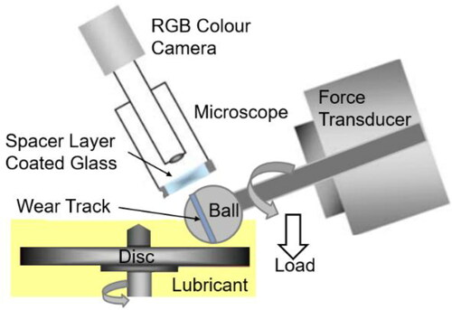
All micropitting tests were conducted using the same method as described in a previous study by the authors (Citation4). An MTM ball-on-disc tribometer with a SLIM attachment was employed both to generate micropitting on the ball specimen and to monitor ZDDP tribofilm formation. The test rig is shown in . A 19.05-mm-diameter steel ball is loaded against a steel disc immersed in lubricant. The ball and the disc are driven by separate electric motors at user-specified rolling–sliding conditions. To capture SLIM images, the rubbing test is paused periodically and the ball is raised and loaded against a glass flat. The glass flat surface is coated with a semi-reflective chromium layer on top of which is a transparent silica spacer layer. Light reflected from the chromium layer and the ball surface undergoes optical interference upon recombination, generating an interference image of the contact between the ball and the glass surface, which is then captured by an RGB camera. Tribofilm thickness is calculated from this interferometric image using calibrated RGB values.
Figure 1. Schematic image of the MTM–SLIM rig.
Test conditions
Two types of rolling–sliding MTM tests were carried out using (Citation1) a rough disc counterface to generate micropitting and measure ZDDP tribofilm at the same time and (Citation2) a smooth disc counterface in slower speed rubbing condition to quantify and compare ZDDP tribofilm formation on steel and BO-coated steel.
Micropitting tests with rough disc counterface
shows the specimen properties and conditions employed in the MTM tests to generate micropitting. Four tribopair combinations were studied: a steel ball–steel disc, a steel ball–BO-coated steel disc, a BO-coated steel ball–steel disc, and a BO-coated steel ball–BO-coated steel disc. In this article, steel–BO denotes an uncoated steel ball rubbed against a BO-coated disc and BO–steel denotes a BO-coated ball against a steel disc.
Table 1. MTM specimen properties (as measured) and contact conditions used in micropitting tests.
Disc roughness and ball hardness were controlled to preferentially create micropitting on the ball. Standard MTM tests utilize very smooth balls and discs with Ra of ca. 5–10 nm. However, in this work, rough AISI 52100 steel discs with Ra = 440 nm were used to subject the smooth counterface ball to severe asperity contact stress cycles and hence promote micropitting generation on the ball. This higher roughness is also more typical of that present in gears and bearing raceways. It should be noted that surface roughness was very slightly reduced after application of BO coating on steel discs. In this work, roughness was measured using a Talysurf stylus profilometer. All roughness values reported in this article are averages of four line measurements taken at four different locations on the same specimen. In the case of fresh specimens (as in ), the measurement length was 1 mm. For worn specimens, the measurement length was approximately 0.5 mm to fit entirely within the width of the rubbed track because the worn roughness values were of interest here. In all cases, lower and upper cutoff lengths were 0.0025 and 0.25 mm, respectively. As is common in controlled micropitting tests (Citation2, Citation3, Citation16, Citation17), the specimen on which micropitting damage is to be studied (balls in this case) was made softer than the rough counterface (discs in this case); this ensures that disc roughness persists during the test, thereby preferentially promoting micropitting on the ball. This was achieved by softening the standard MTM steel balls (martensitic through-hardened AISI 52100 steel) from their normal value of 850 HV down to a measured range of 730–780 HV, by holding the balls at 250 °C for 1 h in PAO 100 base oil in an air atmosphere, followed by cooling. The hardness of BO coating is discussed in detail in the subsection on BO coating properties. Mean speed, SRR (see for definition), load, and oil temperature were the same in all tests. In all cases, the ball surface speed was slower than that of the disc (negative SRR), which again favors formation of micropitting on the balls (Citation18). All tests were carried out at temperature of 65 °C. The chosen maximum Hertzian contact pressure of 1.2 GPa and SRR of −0.05 are representative of rolling bearing and gear conditions. Finally, MTM-SLIM tests were conducted for 40-h duration, which corresponds to 8 million Hertzian contact cycles on the ball.
Tribofilm formation tests with smooth disc counterface
To study the influence of a BO coating on tribofilm formation quantitatively, additional MTM-SLIM tests were carried out using smooth discs in slow-speed rubbing conditions, more typical of those generally used in tribofilm formation studies (Citation19). lists the measured properties of materials and conditions of these MTM tests. Two tribopairs, a steel ball–steel disc and BO-coated steel ball–BO-coated steel disc, were studied. To observe the development of a tribofilm on a BO-coated specimen it is necessary to ensure that the coating survives on the specimen for a sufficient amount of time. To help achieve this, smooth discs with Ra <10 nm and a relatively low load of 15 N (corresponding to a maximum Hertzian pressure of 0.75 GPa) were employed. The tests lasted 180 min in total and were paused for the inspection of specimens after 60 and 120 min.
Table 2. Properties of MTM specimens (as measured) and contact conditions used in tests to measure tribofilm thickness on a BO coating.
Test lubricants
The test lubricant used throughout was a solution of ZDDP (primary–secondary mixed) at a concentration of 800 ppm P in polyalphaolefin base oil (PAO 10, 62.8 and 9.9 mm2/s kinematic viscosity at 40 and 100 °C, respectively). For each MTM test in , 50 mL of lubricant was used to provide the same aging condition of lubricants during the tests. In all experiments, the initial lambda was ca. 0.3 to ensure boundary and mixed lubrication regimes, where lambda is defined as the ratio of the calculated elastohydrodynamic (EHD) film thickness to the initial composite root mean square roughness of the two surfaces.
Although alternative antiwear chemistries are often used in gear oils, ZDDP is employed here because its antiwear behavior and its influence on micropitting in steel–steel contacts is relatively well understood, thus enabling any effects of BO coating to be more readily discerned. This also allows the observations made here to be related to previous relevant studies that also used ZDDP.
BO coating properties
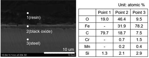
The general properties of BO coatings used in this work are described in (). shows an SEM image of the taper section of a BO-coated steel disc (Ra = 8 nm) and EDX analysis at three points: (1) in the protective resin film, (2) in the BO coating, and (3) in the steel substrate. An approximately 1-µm-thick, uniform BO layer is present on the steel substrate. This layer is mainly composed of iron and a high proportion of oxygen, which roughly corresponds to the chemical composition of Fe3O4.
Figure 2. SEM image of BO-coated steel disc (Ra = 8 nm) and corresponding EDX analyses.
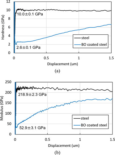
To enable the effect of BO coating on asperity contact pressure to be determined, nanoscale depth profiles of the hardness and elastic modulus of the smooth BO-coated steel discs (Ra = 8 nm) were measured using a Nano Indenter G 200 with a Berkovich tip manufactured by Keysight Technologies. Tests were carried out in the continuous stiffness measurement mode, which allows measurement of the contact stiffness at any point along the loading curve (Citation20). The hardness at each indentation depth was determined by analyzing the amplitude and phase response. The frequency and displacement amplitude values were 45 Hz and 2 nm, respectively. The surface approach velocity was 10 nm/s. With a load range of 50 mN, a target depth of 1.5 µm, and a strain rate of 0.01 s−1, 25 points at 25-µm intervals were obtained. All tests were carried out at room temperature. shows (a) hardness and (b) elastic modulus depth profiles over the 1.5-µm target depth. Generally, true mechanical properties of surface-treated materials can only be determined from indentation data originating from the outermost 10% of the surface treatment because of the well-known substrate effect (Citation21). Thus, measured nanoindentation hardness values were obtained over the range between 0.05 and 0.1 µm because the BO coating was approximately 1.0 µm thick. Measured values were obtained by averaging the values of 25 indentations. shows that the BO coating has hardness of 2.6 ± 0.1 GPa and elastic modulus of 52.9 ± 3.1 GPa, both of which are approximately a quarter of the equivalent values of the AISI 52100 steel used. These values agree well with those previously reported in the literature (Citation22). Although the BO coating is much less stiff than steel, because it is very thin compared to the overall dimensions of the contact, it does not significantly affect the Hertzian contact pressure. This was confirmed by the simulation of contact pressure using an established model for contact of rough layered surfaces (Citation23–26). Therefore, MTM tests were conducted at the same load with specimens with and without the BO coating.
Figure 3. Depth profile of (a) hardness and (b) elastic modulus of steel disc and BO-coated steel disc measured using nano-indentation in continuous stiffness measurement mode. Note that values are taken in the range 0.05–0.1 µm from the surfaces.
Test procedures
The MTM micropitting tests with the conditions in were interrupted after 1,000 cycles and 0.1, 1, and 4 million cycles to observe and measure wear and micropitting on the ball and the current roughness of the disc. The MTM tribofilm thickness tests with the conditions of were stopped after 60 and 120 min to observe the wear tracks on the balls and the discs. In each case, before these surface measurements were conducted at each step, the balls and the discs were rinsed in toluene in an ultrasonic bath for 10 min to remove supernatant oil. Rinsing the ball and disc with toluene did not influence the thickness of the ZDDP tribofilm, which can generally only be removed by chemically active solutions such as ethylenediaminetetraacetic acid (EDTA) (Citation27). This means that rubbing tests can be resumed after each inspection with minimal disturbance. The surface profiles of the ball and disc were then measured in four different locations using a Talysurf stylus profilometer. From these, the maximum wear depths of the ball running track and Ra of the disc were deduced as averages of the four measurements. Micrographs of surface cracks and micropitting on the ball were obtained using an optical microscope. After these measurements, the specimens were returned to the MTM and the rolling–sliding tests were continued. During the tests, the ZDDP tribofilm thickness was measured using SLIM at specified intervals. All tests shown in this article were repeated twice.
ZDDP adsorption using QCM-D
A quartz-crystal microbalance with dissipation monitoring (QCM-D, Biolin Scientific) was used to investigate the adsorption of ZDDP from PAO solution on Fe3O4, representative of BO coating, and also on Fe2O3, believed to be the outermost surface composition of steel. The tests were carried out using the same conditions and procedure as in our previous study (Citation28), employing a sequence of PAO (PAO 4, 18.5 and 4.1 mm2/s kinematic viscosity at 40 and 100 °C, respectively) followed by ZDDP solution in 800 ppm P in PAO 4. The test temperature was 60 °C, which is the maximum temperature achievable on the equipment used.
Calculation of distribution of contact pressure
To determine the influence of the evolving disc roughness (with and without a BO coating) on the evolution of contact pressure distribution, an existing numerical contact mechanics model capable of predicting pressure distribution in layered contacts using real measured roughness was employed (Citation23–26). In these calculations, the Young’s modulus of the steel substrate and the BO coating was 207 and 53 GPa, respectively, the Poisson ratio was 0.3 for both materials, and the coating thickness was 1 µm as measured earlier. The surface profiles used as input to the model were obtained using a Talysurf stylus profilometer.
Results
Effect of BO coating on micropitting
This section presents the results of the influence of BO coating on micropitting. MTM tests were conducted according to the conditions listed in .
Evolution of surface damage on balls
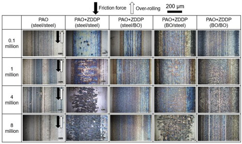
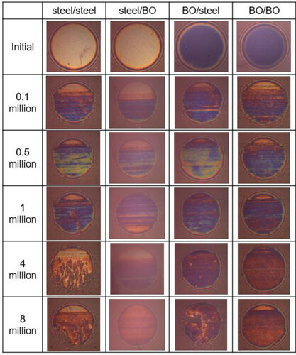
shows representative optical micrographs of the wear tracks on the balls from the steel–steel, steel–BO, BO–steel, and BO–BO tribopair tests after 0.1, 1, 4, and 8 million cycles. The blue color in these images indicates the presence of a ZDDP tribofilm. The extent of micropitting damage in terms of density of cracks and pits varied somewhat over the ball rubbing track. The images shown here illustrate the typical extent of damage for each material combination. In steel–steel and BO–steel tests, cracks formed on the balls after 0.1 million cycles. At 1 million cycles these cracks grew to a length of tens of micrometers across the rolling track in a fanned, shallow “V” shape, typical of surface-initiated contact fatigue. As the test progressed, the number of cracks significantly increased and they started to interact and join up. After 4 million cycles, small pits (tens of micrometers in size) associated with these cracks became apparent. After 8 million cycles, these micropits covered large areas of the wear tracks in these two cases. By contrast, cracks and micropits were not observed on the balls in the tests with steel–BO and BO–BO tribopairs at any time throughout the 8 million cycle tests. The actual percentage of micropitted area on the entire ball wear track after 8 million cycles was estimated. This was obtained by taking a series of optical images to cover the entire ball wear track and then manually identifying the size of the area covered by cracks and micropits in each of these images as a percentage of the wear track. The reported value is the average of all values obtained in the individual image and therefore represents an estimate of the total extent of micropitting over the entire wear track rather than just the example image shown in to account for any variability in the damage along the ball circumference. For steel–steel and BO–steel tribopairs, this was 27 and 25%, respectively, and for BO–BO and steel–BO it was zero because no micropitting was observed anywhere in the wear track. These results show that micropitting can be successfully prevented when the rougher, harder disc is coated with BO regardless of whether the ball is coated. In contrast, micropitting always occurred when the rough disc was not coated, regardless of whether the ball was coated.
Figure 4. Optical micrographs of wear tracks on MTM balls at different numbers of loading cycles from micropitting tests with steel–steel, steel–BO, BO–steel, and BO–BO tribopairs. The percentage of micropitted area on the ball wear track after 8 million cycles is shown in the micrographs. The scale bar included in the top right corner of the figure applies to all images shown.
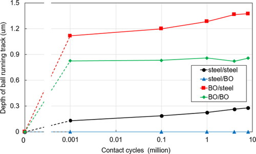
An attempt was also made to measure the evolution of loss of material on the balls due to conventional mild wear, as opposed to micropitting. This was done to capture any loss of the BO coating through wear, but it also helps to understand the mechanisms at play because mild wear is known to compete with micropitting (Citation4, Citation15). The average wear depth of the ball rubbing track was obtained from stylus profilometer measurements taken at four locations around the ball circumference. In the case of micropitted balls from steel–steel and BO–steel tests, care was taken to avoid micropits so that the obtained maximum depth was not distorted by any deep, discrete micropits and hence represents loss of material due to general mild wear. Any ZDDP tribofilm that may have been present in the tracks was not removed prior to making these measurements so that rubbing tests could be resumed after each inspection without introducing unwanted disturbances. The presence of any ZDDP tribofilm would therefore potentially act to make the measured wear depths in this plot smaller than they actually were. However, because the maximum ZDDP tribofilm thicknesses observed in this work were on the order of 100 nm (see and ), the effect of this in practice is inconsequential to the presented trends given that the measured wear depths were up to 1.1 µm.
shows the maximum depth of the wear tracks on the balls obtained in this way. It is evident that the steel–BO tribopair produced almost no material loss on the ball. The steel–steel tribopair produced only a relatively small amount of mild wear, with a maximum wear track depth (outside micropitted areas) <0.3 µm after 8 million cycles. In contrast, the BO–steel and BO–BO tribopairs resulted in a high amount of material loss due to wear on the BO-coated balls very early in the tests, with 0.83- and 1.1-µm wear depths, respectively, after 1,000 cycles. However, after the initial 1,000 cycles there was no further loss of material from the ball in the case of the BO–BO disc. The reasons for this are discussed in more detail below (Mechanical effects of black oxide on micropitting (discussion part)) but are likely due to the fact that once the harder steel substrate is exposed on the ball it resists further damage when rubbed against the counterface disc, which has been significantly smoothened by this time due to BO coating wear. Material loss from the ball due to wear in the BO–steel test (outside micropitted areas) continued after 1,000 cycles but the rate of loss decreased drastically to become similar to that seen on the balls from steel–steel tests. In this case, the continued loss of material was likely due to continued mild wear induced on the ball by the steel disc, which remained rough throughout the test as in the case of the steel–steel pair. Considering that the BO coating has an approximately 1 µm thickness, these results suggests that most of the BO coating on the balls was removed by wear in the first 1,000 cycles, well before micropitting damage was initiated on the balls. Finally, given that ZDDP tribofilms were observed in all four tribopairs (indicated in blue in ) at and after 1,000 cycles, this implies that these ZDDP tribofilms continued to grow on the steel substrate after the early removal of the BO coating.
Figure 5. Measured depth of the ball wear track due to conventional wear (i.e., outside micropitted areas) from tests with steel–steel, BO–steel, steel–BO, and BO tribopairs. The dashed line up to 1,000 cycles is to guide the eye. It is unknown whether the increase in material loss was linear with log (cycles) up to this point and the increased material loss shown at 1,000 cycles may have occurred earlier.
Evolution of surface roughness of counterface discs
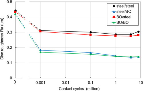
shows the evolution of the disc roughness during the tests. In all cases, the disc roughness was significantly reduced in the initial stages of the test and then remained relatively stable thereafter, behavior indicative of running-in. However, considerable differences were evident between noncoated and BO-coated discs. The steel–steel and BO–steel tribopairs (i.e., cases where the disc was not coated) showed a reduction in disc roughness from the initial Ra value of 0.44 µm to approximately 0.3 µm after 1,000 cycles, which remained constant for the rest of the test. In contrast, in the tests where the disc was coated, namely, steel–BO and BO–BO, disc roughness was reduced much more quickly in the initial period of the test, from 0.42 µm to approximately 0.18 µm after the first 1,000 cycles; it then remained relatively constant, reaching approximately 0.13 µm after 8 million cycles at the end of the tests. These results show that steel discs coated with BO experienced a very considerable reduction in roughness very quickly after the start of the test, within the first 1,000 cycles, which corresponds to 30 s of rubbing.
Figure 6. Evolution of disc roughness in the test with steel–steel, BO–steel, steel–BO, and BO–steel tribopairs. The dashed line up to 1,000 cycles is to guide the eye. It is unknown whether the reduction in roughness was linear with log (cycles) up to this point and the amount of roughness reduction shown at 1,000 cycles may have occured earlier.
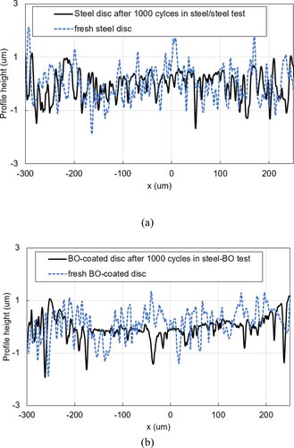
shows the corresponding surface profiles of the steel and BO-coated discs when fresh and after 1,000 cycles in tests against a steel ball. These profiles clearly indicate that after 1,000 cycles, the roughness peaks of the BO-coated disc were considerably more polished than those of the steel disc under the same test conditions. This is in agreement with the results of .
Figure 7. Disc surface profiles recorded before the test and at 1,000 cycles for (a) steel disc tested against a steel ball and (b) BO-coated disc tested against a steel ball.
Friction behavior
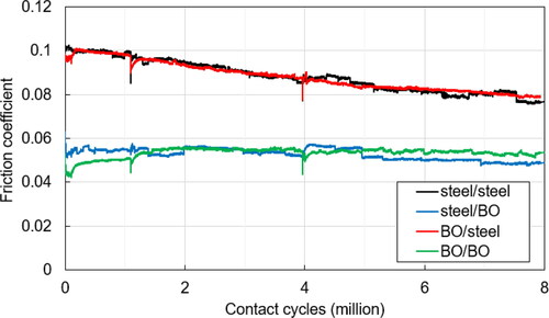
shows the evolution of the friction coefficient in tests conducted with the four tribopair combinations. The friction coefficient obtained in the test with steel–steel and BO–steel was initially ca. 0.1 and gradually decreased to 0.08 at the end of the test. By contrast, the friction coefficient just after the start of steel–BO and BO–BO tests was 0.05 and it remained relatively constant for the rest of the test. It should be noted that the first friction measurement in the MTM rig is recorded at 550 cycles. This result is in line with the rapid running-in of the BO-coated disc shown in and : The high surface roughness of the steel discs generated high friction as the contact operated in mixed lubrication conditions, but when BO coating was applied to rough steel discs, their roughness decreased almost immediately after the tests began, resulting in an increase in the lambda ratio and thus a significant drop in the friction coefficient. It should be noted that the momentary blips in the recorded friction traces apparent in are artifacts of the measurement method and occurred just after motion was paused for capture of a SLIM image.
Figure 8. Measured friction coefficient in MTM micropitting tests with steel–steel, BO–steel, steel–BO, and BO–BO tribopairs.
Evolution of ZDDP tribofilm in micropitting tests
shows representative SLIM images of the ball tracks at different times during four micropitting tests. Because the BO-coated balls were less reflective than the uncoated balls, light intensity was adjusted to obtain clear SLIM images from BO-coated balls during the tests; this is the reason for the different color of the first images of the BO-coated balls in . Though the development of cracks and micropits on the ball surface are apparent in the SLIM images from the tests of steel–steel and BO–steel tribopairs, this damage was not observed on the ball wear tracks of steel–BO and BO–BO tribopairs. This corresponds with the observations made in . SLIM images indicate that similar ZDDP tribofilms formed on the balls in all four tribopair combination.
Figure 9. SLIM images of the ball running track recorded in tests with steel–steel, BO–steel, steel–BO, and BO–BO tribopairs (steel/BO means steel ball on BO-coated disc and vice versa).
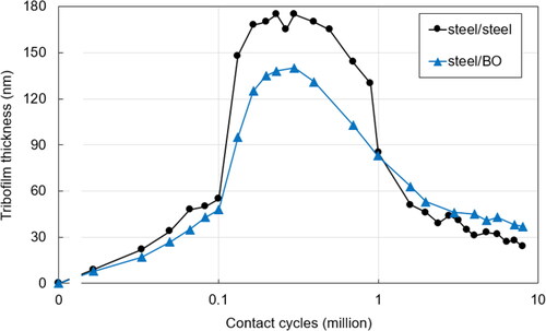
shows the tribofilm thickness in the middle region of the ball rubbed tracks obtained from SLIM images for steel–steel and steel–BO tests. Unfortunately, the low reflectivity of the BO-coated balls, combined with the fact that the BO coating was rapidly worn off, meant that the thicknesses could not be reliably quantified from SLIM images of the BO-coated balls. The initial rate of tribofilm growth for steel–BO appeared to be slightly smaller than that for steel–steel, but the two were very similar for all practical purposes. After 0.1 million cycles, the tribofilm in the steel–steel test continued to grow rapidly to reach approximately 180 nm after 0.3 million cycles, whereas that in the steel–BO test grew more slowly, reaching 140 nm after 0.3 million cycles. This difference in the tribofilms on steel balls rubbed against a steel disc and BO disc is also evident in the SLIM images of at 0.5 million cycles, where relatively thicker tribofilms, indicated in green in the figure, appear to exist on the coated and uncoated balls rubbed against steel discs compared to those rubbed against BO coated disc. It may be that the lower friction resulting from fewer or milder asperity contacts generated by the worn BO-coated discs results in thinner tribofilms on the balls (Citation29, Citation30) at this stage of the test. The tribofilms then continually reduced in thickness and became very similar for all tribopairs after about 1 million cycles, where they were ∼85 nm and dropped to ca. 30 to 40 nm at 8 million cycles.
Figure 10. Tribofilm thickness evolution in the middle of the ball wear tracks for steel–steel and steel–BO tribopairs obtained from the corresponding SLIM images.
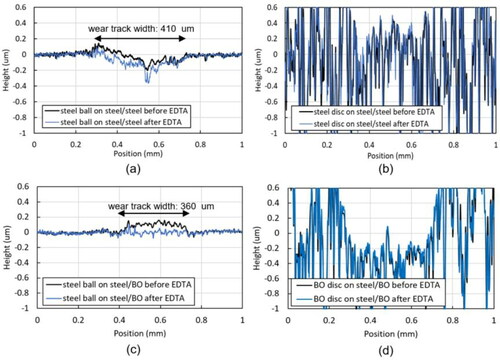
The results above describe tribofilm formation on the balls, but it was also of interest to assess tribofilm formation on the discs. shows surface profiles of the balls (a and c) and the discs (b and d) from tests with steel–steel and steel–BO tribopairs after 0.1 million cycles, obtained using a Talysurf stylus profilometer. In all cases, profiles are shown before and after EDTA treatment, where EDTA treatment was used to remove the ZDDP tribofilms from the surfaces (Citation31). The results show that whereas tribofilms of 50–100 nm thickness were formed on both of the balls, no measurable tribofilms were observed either the steel or BO-coated disc from the steel–steel and steel–BO tribopair tests. As shown in , most of the decrease in the surface roughness of the discs occurred between 0 and 1,000 cycles. This continuous asperity removal may inhibit the growth of a tribofilm on the discs up to this point in the tests and hence no tribofilms were observed at 1,000 cycles. However, it is difficult to accurately measure tribofilm thickness on such rough surfaces using a stylus profilometer, so the existence of a tribofilm cannot be excluded.
Figure 11. Surface profiles of balls and discs at 0.1 million cycles measured using a stylus profilometer before and after EDTA treatment (EDTA applied to remove any ZDDP tribofilms, without moving the specimen) for (a) the ball from the steel–steel test, (b) the disc from the steel–steel test, (c) the ball from the steel–BO test, and (d) the disc from the steel–BO test.
Influence of BO coating on ZDDP tribofilm formation using smooth discs
Because it was not possible to obtain meaningful SLIM measurements of ZDDP tribofilms on BO-coated balls in the above tests with rough discs, further tests were conducted at more benign conditions to ensure survival of the BO coating on the balls for long enough to assess its influence on ZDDP tribofilm formation. To achieve this, tests were conducted with smooth balls and discs at low entrainment speed and relatively low load conditions over 180 min (conditions listed in ). The ZDDP tribofilm growth was assessed in tests with a steel ball on a steel disc and a BO-coated ball on a BO-coated disc.
Wear of balls and discs
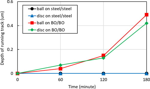
shows the evolution of wear depth of the balls and discs in tests with steel–steel and BO–BO tribopairs. Though no measurable wear was observed on the ball or the disc from the steel–steel test, some wear of both surfaces was seen in the tests with the BO–BO tribopair. The wear was continuous throughout the test and the maximum wear depth at the end of the 180-min test was 0.50 and 0.42 µm for the BO-coated ball and the BO-coated disc, respectively. Given that the thickness of BO coating was approximately 1.0 µm, this indicates that some BO coating remained at the end of these tests.
Figure 12. Wear evolution of the balls and discs from tests with steel–steel and BO–BO tribopairs using smooth specimens and conditions listed in . (The BO coating thickness was approximately 1 µm.)
Friction behavior
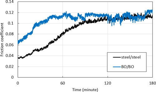
shows the friction coefficient evolution of steel–steel and BO–BO tribopairs under conditions listed in . For the steel–steel tribopair, the friction coefficient was around 0.04 at the beginning of the test, and this gradually increased to stabilize at approximately 0.11 after 120 min. By contrast, the BO–BO tribopair initially had a higher friction coefficient, around 0.06, which then increased at a similar rate to the steel–steel contact to reach 0.11 after 60 min. BO–BO friction showed greater fluctuations during the 180-min test than the steel–steel contact. It is well known that the growth of a ZDDP tribofilm can increase the friction coefficient in mixed lubrication conditions because its pad-like structure can increase the roughness of the rubbing surfaces, particularly if the latter are very smooth to start with, resulting in a reduction of the effective lambda ratio and consequent transition from mixed to boundary lubrication (Citation32). Because both steel–steel and BO–BO tribopairs showed an increase in friction from an initially lower value to 0.11–0.12, which corresponds to friction of ZDDP tribofilms in boundary lubrication, this behavior suggests that ZDDP tribofilms were built up in both cases during the initial phases of rubbing. Unlike in the steel–steel contact, some wear occurred on the BO–BO tribopair, which presumably also removed the ZDDP tribofilm from the rubbing surface. This continuous tribofilm removal and formation may have resulted in the relatively unstable friction coefficient of BO–BO contact during the test.
Figure 13. Friction coefficient of steel–steel and BO–BO tribopairs under test conditions listed in .
Observation of ZDDP tribofilm formation
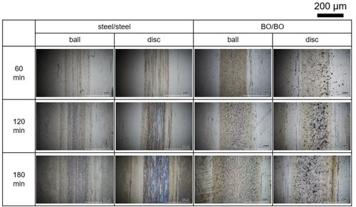
shows optical micrographs of the wear tracks of the balls and discs from steel–steel and BO–BO tests under conditions listed in after 60, 120, and 180 min. After 60 min, the surfaces of steel and BO specimens appeared relatively similar. After 120 and 180 min of rubbing, whereas a ZDDP tribofilm, indicted in blue, was present on the steel ball and disc, no such tribofilm was observed on the BO-coated ball and disc.
Figure 14. Optical micrographs of the ball and the disc wear tracks at different times during the tests with steel–steel and BO–BO tribopairs.
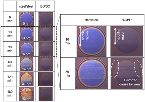
shows the SLIM images obtained from the balls at various times during the steel–steel and BO–BO tests. To help observe the tribofilm formation more clearly, magnified SLIM images after 10- and 30-min rubbing are included. Note that SLIM images obtained from the BO-coated ball are darker than those from the steel ball because of BO’s low reflectivity. Quantitative tribofilm thickness values for steel–steel tests obtained from these SLIM images are included in the respective images in . A tribofilm grew steadily on the steel–steel contact during the test to reach ca. 40 nm after 180 min of rubbing. Although the tribofilm thickness could not be quantified on the BO-coated ball due to its low reflectivity, some tribofilm formation on BO is clearly visible in the SLIM images, with a color change on the wear track of the BO-coated ball observed after 10 min of rubbing. Unlike in the steel–steel contact, the edges of the nominally circular ball–flat contact area in the SLIM images from the BO–BO tests are distorted, indicating some wear of the BO-coated ball.
Figure 15. SLIM images obtained from the ball wear tracks of steel–steel and BO–BO tribopairs.
Based on the increase in the friction coefficient () and the optical micrographs (), a ZDDP tribofilm initially formed and grew on the BO-coated ball and disc in a similar fashion to that in the steel–steel tests. However, the ZDDP tribofilm on the BO balls after this initial period appeared to be thinner than that on steel balls, as is evident in the images in , probably due to continuous wear of the very soft BO coating, which effectively prevented further buildup of the ZDDP tribofilm on the BO surface.
ZDDP adsorption on black oxide coating
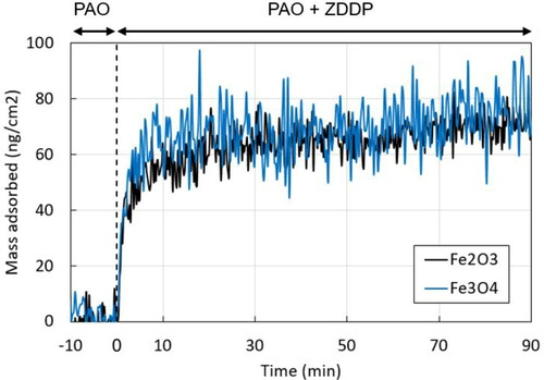
Because the ability of ZDDP to adsorb on surfaces has a significant influence on tribofilm formation and growth (Citation28), to further understand the interaction of ZDDP with BO surfaces, the adsorption of ZDDP on Fe3O4, present in BO, and Fe2O3, believed to be the composition of the outermost surface of steel, was studied using QCM-D. shows ZDDP mass adsorbed at 60 °C on sensors made of each of these materials. After the replacement of PAO with a ZDDP solution, ZDDP adsorbed on both surfaces at the equivalent rate for 90 min to reach approximately 70 ng/cm2 mass adsorbed. This result shows that ZDDP should adsorb on BO coatings to an extent similar to that on steel surfaces.
Figure 16. ZDDP adsorption on Fe2O3 and Fe3O4 using QCM-D.
Discussion
The results presented in this article clearly show that the BO coating can effectively reduce, or even prevent, micropitting but only when it is applied to the rougher and harder of the two rubbing surfaces, in this case the disc specimens. The BO coating is largely ineffective in terms of micropitting prevention when applied solely to the softer, smoother body, in this case the ball specimens. This basic observation is of obvious practical importance and is in line with the results reported by other authors (Citation5). The present results also offer some important insights into the actual mechanism by which BO is able to mitigate micropitting. Previous studies have suggested that the low hardness of BO coatings provides fast running-in of initially rough surfaces, which means that the contact operates under relatively low asperity stresses throughout its lifetime (Citation5, Citation7, Citation8, Citation10, Citation12, Citation33), which mitigates microcrack growth and thus micropitting. However, it has also been suggested that it is the suppression of the buildup of a ZDDP antiwear tribofilm on the rough counterface by the BO coating that is essentially responsible for the rapid running-in and hence the reduction in micropitting (Citation5).
It is relatively well accepted that the chemical composition of rubbing surfaces can affect their reactivity with lubricant additives, including ZDDP, and hence their ability to form tribofilms (Citation28, Citation34, Citation35). Additionally, it has been suggested that the ZDDP reaction mechanisms on an Fe3O4 surface containing Fe2+ and Fe3+ ions, as may be expected to be present in the BO coating, and the resulting tribofilm properties might be different from those on the predominantly Fe2O3 surface normally present on steel (Citation13, Citation14). Therefore, it is quite plausible that that BO coating might affect ZDDP tribofilm formation. Given that the rate of ZDDP tribofilm buildup is known to strongly influence micropitting propensity (Citation4), this potential interference of the BO coating with the development of a ZDDP tribofilm through chemical means warrants further consideration as a potential mechanism by which BO mitigates micropitting. In this section the potential mechanisms by which BO coating mitigates micropitting are discussed considering both chemical and mechanical effects.
Chemical effects of black oxide on micropitting: Interaction of BO with ZDDP tribofilm buildup
Under the relatively harsh conditions employed for the micropitting tests (), it was not possible to reliably observe ZDDP tribofilms on the BO coating itself because the coating was worn off almost immediately at the beginning of the tests. In this case, any tribofilms apparent in the SLIM images of the BO-coated balls in were likely exist on the steel substrates, which were exposed after removal of the original BO coating. However, ZDDP tribofilm growth on BO-coated balls was successfully observed in the tests conducted at the more benign contact conditions listed in . The results of these tests show that in the initial stages of rubbing, ZDDP forms tribofilms on the BO coating in a similar fashion to that on steel. This was further supported by the results of the QCM-D absorption tests performed, which showed that ZDDP adsorbed similarly on Fe3O4, as present in BO, and Fe2O3, as may be present on uncoated steel surfaces. As the test progressed under these mild conditions, the ZDDP tribofilm on the BO coating grew but did not reach as great a thickness as that on steel under the same conditions, as is evident in the images in . This was probably because the continuous wear of the BO coating, which was observed in these tests, resulted in continuous tribofilm removal. The presence of wear despite the evident tribofilms suggests that any ZDDP tribofilms formed on the BO coating were not sufficient to protect the BO coating from wear even under the mild rubbing condition used in these tests (as listed in ). Given that bearings and gears normally operate under more severe conditions than those in , rapid wear of the BO coating is very likely to occur in practical situations.
Overall, the fact that ZDDP forms tribofilms on BO coatings that are, at least initially, similar to those formed on steel under the equivalent conditions suggests that the mechanism by which BO coating mitigates micropitting is not related to its chemical properties or to interference with ZDDP tribofilm buildup but most likely originates predominantly from its mechanical properties, such as its low hardness.
Mechanical effects of black oxide on micropitting
The hardness and elastic modulus of the BO coating were found to be only about one-quarter those of steel. In principle, this might help to reduce micropitting in three ways, all of which are related to the impact of BO on reducing asperity stresses and thus microcrack formation and growth:
The relatively low hardness of BO may enable faster running-in of the rough surface so that the flatter asperities reduce local asperity stresses.
The lower elastic modulus of the BO may directly reduce asperity pressures by increasing areas of asperity microcontacts (the same does not hold for the macro contact area because the coating thickness is much smaller than the size of the contact and so has a negligible influence on a macro scale).
The BO might act to directly reduce asperity friction and hence local tensile stresses, which can be particularly detrimental in terms of crack initiation and propagation.
and clearly show a strong effect of BO on the running-in of the rough disc counterface where the asperity peaks present on the virgin surface have been significantly reduced, much more than in the case of equivalent steel–steel contact. To quantify how beneficial this running-in might be in terms of reduction of asperity pressures, an existing numerical contact mechanics model was used to predict asperity pressure distributions before and after running-in. The reader is referred to the literature (Citation24–26) for full details of this model but, in brief, the model is based on the influence coefficient approach and uses real, measured roughnesses as input and can deal with single or multilayered surface coatings. The model is capable of 3D simulations but in the examples shown here, it is run in 2D by setting the applied load to match the maximum Hertzian pressure used in the experiments; that is, 1.2 GPa. In the present simulations, the BO coating is modeled as a layer with a thickness of 1 µm with an elastic modulus of 53 GPa (as measured here; see ) on a steel substrate with an elastic modulus of 207 GPa. The Poisson ratio was set to 0.3 for both the coating and the substrate. Although all cases presented here were run with the full model, accounting for the presence of the 1-µm BO coating, the coating was in fact predicted to have a negligible influence on the asperity pressure distribution because of its very small thickness. This suggests that the second of the three potential mechanisms listed above by which the BO can mitigate micropitting, namely, that it directly reduces asperity contact pressures because its elastic modulus is much lower than that of steel, is not of great significance. Given the significant wear of the BO coating with both rough and smooth specimens, any small effects of the coating on asperity elastic pressures would be overwhelmed by the much more significant changes in roughness.
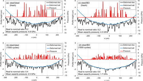
shows the predicted pressure distributions for steel–steel and steel–BO tribopairs with both the fresh specimen roughnesses and the roughnesses measured after 1,000 cycles. The estimated ratio of real to nominal contact area and the mean asperity pressure are also shown in each of the four cases. To clearly illustrate the effects of running-in, a purely elastic solution is shown in all cases; note that the elastic assumption does produce asperity pressures at a few discrete points in the case of fresh surfaces () that are perhaps unrealistically high (being just over the plastic limit), but the plasticity was deliberately not modeled to avoid obscuring the differences in contact pressure distributions between the fresh and run-in samples. Indeed, it is evident that for both tribopairs after 1,000 cycles, asperity pressures at all points are below the plastic limit for the steel used (through-hardened AISI 52100), confirming that any plastic deformation had already taken place by this time and that the contact was now purely elastic. In the case of fresh specimens, the real/nominal contact area ratio was ∼0.2 and the mean asperity pressure was over 4 GPa for both steel–steel () and steel–BO () contacts. These values are typical for a contact of rough surfaces made of hard steels. After 1,000 cycles, the real-to-nominal area ratio for the steel–BO tribopair was 0.6, considerably larger than that for the steel–steel contact, which was 0.4. The corresponding mean asperity pressures were approximately 1.7 GPa for the steel–BO contact and 2.5 GPa for the steel–steel contact. The larger contact area and the generally lower asperity pressures for the steel–BO contact compared to steel–steel are evident in the corresponding pressure distributions shown in . These quantitative results confirm the first of the three potential mechanisms listed above by which BO coating can reduce micropitting damage: It provides for enhanced running-in, which reduces asperity pressures and hence reduces surface fatigue damage accumulation and micropitting. Given that bearing life theories suggest that contact fatigue life is inversely proportional to the applied contact stress to the power of around 9 (Citation36), the effect of mean asperity pressure reduction from 2.5 to 1.7 GPa on micropitting damage is likely to be considerable.
Figure 17. Predicted surface pressure distribution and deformation for (a) steel–steel contact with original (fresh) roughness, (b) steel–steel tribopair with roughness measured after 1,000 cycles under conditions in , (c) steel–BO tribopair with fresh roughness, and (d) steel–BO tribopair with roughness after 1,000 cycles. All roughnesses measured using a stylus profilometer. (Purely elastic solution shown in all cases to clearly illustrate the effects of running-in; this may result in some asperity pressures with fresh roughnesses appearing unrealistically high).
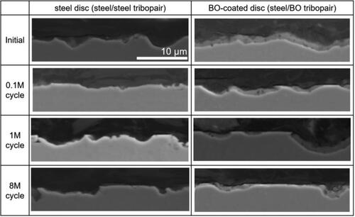
To further investigate the manner in which the BO coating enhances the running-in process, cross sections of the steel disc from the steel–steel and the BO-coated discs from the steel–BO micropitting tests were inspected at different numbers of cycles using SEM. The resulting images are shown in . The cross sections of the fresh discs show that BO was evenly coated on the rough steel substrate. The images of the discs after 1,000 cycles show that the BO coating was removed from the asperity peaks and that the tops of these peaks were flattened in many places, producing flat plateaus. At the flattened regions of the BO-coated disc, no BO coating remained and steel substrate was exposed. In contrast, the BO coating was still intact in the valleys, and its thickness in these regions was, at 1 µm, more or less the same as that in fresh specimen. This combination of the coating being worn off the peaks and surviving in the valleys resulted in the worn BO-coated surface having much lower surface roughness than that of the equivalent worn uncoated disc. In addition to the effect this has on reducing asperity stresses as discussed above, it is possible that the additional beneficial effect of flatter peaks and shallower valleys is one of improved micro-EHD lubrication in the asperity microcontacts (Citation37, Citation38). It is, of course, very difficult to provide direct observations of micro-elastohydrodynamic lubrication (EHL) conditions, which is outside the scope of the present study, but if this effect were indeed present, it would serve to further alleviate asperity normal stresses and reduce asperity friction, both of which would mitigate micropitting.
Figure 18. SEM images of cross sections of the steel disc from the steel–steel test and BO-coated disc from the steel–BO test at different numbers of cycles under micropitting test conditions in . The scale bar shown in the top right image is applicable to all images.
The third potential mechanism mentioned above is that BO coating provides a lower friction coefficient than uncoated steel and thereby reduces asperity tensile stresses and hence micropitting. shows that with rough counterface discs in micropitting tests, friction is much lower in tests where the disc has a BO coating than when it is uncoated. When only the smooth ball is coated, friction is practically the same as that for steel–steel contacts. However, in tests with smooth counterface discs, friction is initially higher with BO-coated discs than with uncoated discs, as shown in . This difference is believed to occur due to tests with rough and smooth counterface discs operating in different lubrication regimes. In rough counterface tests, because of the high roughness of the discs, the contact starts in mixed/boundary lubrication (lambda ∼0.3) for both uncoated and BO-coated counterface discs. With steel discs, as running-in progresses, there is a slow transition from the boundary regime to mixed lubrication (lambda ∼0.5), with a corresponding friction reduction. However, for BO-coated rough discs, very rapid smoothening of rough discs occurs, and this results in an almost immediate transition to conditions of EHD lubrication (lambda ∼1.0) at these test conditions, in particular because of the relatively high entrainment speed of 3 m/s. This occurs before the first MTM friction measurement is recorded at 550 ball loading cycles (10 s after the start of the test). Thus, the low friction shown in for the tests with BO-coated discs does not represent an inherently low boundary friction coefficient of the BO coating itself; rather, it is a result of partial fluid film lubrication existing at this time. This conclusion is also supported by the fact that when only the ball (much smoother than the discs and hence not affected by running-in) was coated with BO, the friction was the same as that in steel–steel contacts. Further evidence for this is provided by the SEM images in . These show that negligible BO coating is left on the tops of asperity peaks after 1,000 cycles so that if the contact were still operating in a boundary/mixed regime, friction after this time would have been expected to be the same as for steel–steel contacts, which was not the case. Friction recorded in the smooth surface tests, where BO was not completely removed from the asperity peaks and less running-in occurred, indicate that BO coating actually has a higher initial friction against itself than steel on steel (). As the test progressed, a rough ZDDP tribofilm developed on both BO and steel, which pushed the contact further toward the boundary regime, and this caused the friction coefficient in both cases to increase to about 0.11, which is typical for the boundary friction of ZDDP tribofilms. This same friction was reached for both steel–steel and BO–BO tribopairs. It thus seems unlikely that BO reduces micropitting by directly reducing the asperity friction coefficient. Of course, the presence of BO can still reduce the magnitude of asperity shear stresses indirectly, via the enhancement of the running-in process and the subsequent reduction in the magnitude of the asperity pressures (as shown in ), which also lowers asperity shear stresses. In addition, any potential improvements in the micro-EHL lubrication conditions afforded by the running-in of the asperity peaks when coated by BO, as briefly discussed above, would also help to reduce shear stresses in the asperity contacts.
Though mitigation of micropitting using a BO-coated counterface has been observed in multiple studies using lubricants containing either ZDDP or ashless antiwear additives, a study by Mahmoudi et al. (Citation39) stands out because it showed that in tests with pure base oil and with BO coating on both rubbing steel components (i.e., a BO–BO tribopair), no reduction of micropitting was observed compared to a steel–steel tribopair under the same conditions. We have shown in our previous study (Citation4) that as long as scuffing does not occur, the very limited wear protection provided by an additive-free base oil results in extremely rapid reduction of roughness and substantial amounts of adhesive wear of the components, both of which act to prevent formation and propagation of surface cracks and hence suppress micropitting regardless of other conditions imposed. Mahmoudi et al. (Citation39) did not present measurements on the evolution of surface roughness in their tests, but it is probable that due to their use of pure base oil, the surface roughness of the rough counterface in their steel–steel tribopair was rapidly decreased to mitigate micropitting to an extent similar to that with the BO–BO tribopair. This excessive wear would have masked any relative improvement in micropitting otherwise afforded by the BO coating, leading to their observation of no difference in micropitting between steel–steel and BO–BO tribopairs in the tests with pure base oil.
Summary of the mechanism by which black oxide coating mitigates micropitting
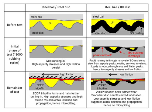
Based on the results and discussion presented in this article, the primary mechanism by which BO coating is able to mitigate micropitting when applied to a rough counterface is summarized schematically in . The relevant steps in this mechanism are as follows:
Figure 19. Schematic illustration of the primary mechanism by which BO coating mitigates micropitting.
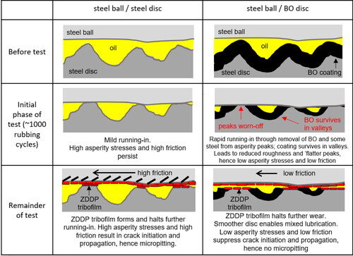
Before the tests
Black oxide was applied as a uniform thickness conversion coating on the rough counterface (AISI 52100 steel disc in the present tests). This very slightly reduced the surface roughness compared to a fresh uncoated surface, but this roughness reduction was insufficient to significantly affect micropitting.
Very early stages of rubbing
Due to the low hardness of the BO conversion coating, the BO coating as well as some steel substrate immediately underneath were rapidly removed from the very tops of the asperities that participated in the initial contact. This occurred in the first few hundreds of cycles and before any significant ZDDP tribofilm formed on the surface. This resulted in a very considerable reduction in surface roughness of the (initially) rough counterface. The large reduction in roughness means that the contact then operated in the mixed lubrication regime, away from the boundary regime and closer to full film lubrication, with a consequent overall friction coefficient reduction. The polishing of asperity tips means that contact pressures, and hence shear stresses, in asperity microcontacts were reduced. The BO coating was not removed from the valley regions, and this further contributed to the reduction in roughness. It may also improve the micro-EHL lubrication at asperity conjunctions and hence further reduce asperity-level stresses.
Some running-in also occurred in equivalent steel–steel contacts, but owing to much higher hardness of steel, the roughness reduction in this case was vastly smaller than that for a BO-coated surface so that asperity stresses continued to be relatively high.
Remainder of the tests
A ZDDP tribofilm was seen to be formed on the rubbing surfaces in tests with both steel–BO and steel–steel tribopairs, although it was somewhat thinner in the case of steel–BO. This ZDDP tribofilm, which was formed mainly on the balls, was sufficient to effectively protect the rubbing surfaces from further excessive wear for both steel–steel and steel–BO tribopairs. Note that at this stage, BO was removed from the contacting asperities, so the tribofilm formed mainly on the underlying steel. This tribofilm suppressed any further running-in of surface roughness. With steel–steel tribopairs, the contact operated under higher friction and the asperities continued to experience high pressures and shear stresses and a large number of stress cycles, all of which promoted initiation and propagation of surface cracks through the remainder of the test, thus causing micropitting. With steel–BO tribopairs, effective polishing of the asperity tops and the persistence of BO coating in the valley regions means that the contact operated under a higher effective lambda ratio and consequently lower friction, even if still in mixed lubrication. The lower slopes of asperity peaks mean that the magnitude of asperity pressures was also reduced. All of this led to a substantial reduction in the normal and shear (and hence tensile) stresses acting on asperities and hence successfully mitigated micropitting throughout the test.
Our observations and discussion show that a BO coating applied to a rough steel counterface can effectively reduce micropitting and result in low wear of steel substrates by facilitating the running-in and hence reduction of roughness in the very early stages of rubbing even in the presence of a ZDDP tribofilm. As with ZDDP-containing oils, this reduction in micropitting is also likely to occur with oils containing ashless phosphorus-based antiwear additives that are commonly used in gear oils. This has practical implications in tailoring surface materials and optimizing lubricant formulations to improve surface fatigue resistance and antiwear behavior of rolling–sliding contacts in a given mechanical system.
Conclusions
The present study used an MTM-SLIM ball-on-disc tribometer to investigate the effect of BO conversion coating on the occurrence of micropitting damage in lubricated contacts of bearing steel specimens. This was complemented by various material analysis techniques and a numerical model for rough surface contacts. We present results to show how the BO coating can effectively mitigate against micropitting and, based on our observations, suggest the relevant mechanisms at play. The key conclusions are as follows:
Application of a BO coating to the rougher, harder counterface (steel discs in the present MTM tests) prevents the occurrence of micropitting damage on the mating surface (MTM ball in the present study) regardless of whether this mating surface is also coated or not. This reduction in micropitting afforded by BO exists even in the presence of ZDDP-containing oils, which usually promote micropitting. In contrast, application of BO to the smoother, softer counterface only has no effect on micropitting, and in this case the damage is the same as that observed in uncoated steel–steel contacts.
The mechanism by which BO coating reduces micropitting is essentially through optimization of the running-in process and consists of the following steps:
BO coating is rapidly removed from the tops of the surface asperities shortly after the onset of rubbing. BO coating survives in the roughness valleys. This results in an almost immediate and very significant reduction in overall disc surface roughness as well as a reduction in asperity slopes.
These changes in roughness lead to a rapid reduction in asperity pressures, and hence shear stresses, and an increase in the effective lambda ratio to provide a reduction in the overall contact friction. This reduction in asperity normal and tangential stresses leads to a reduction in initiation and propagation of surface fatigue cracks and thus less micropitting than found in an equivalent steel–steel contact where the running-in process is not as effective.
With further rubbing, an effective antiwear boundary film forms, mainly on the exposed steel substrate, and prevents further wear of the surface.
The key to this behavior is the low hardness of the BO coating, which was measured as only one-quarter that of the steel substrate. This means that BO coating can be easily worn from the asperity peaks to reduce surface roughness and asperity slopes within the first few hundred rubbing cycles.
In mild rolling–sliding test conditions with relatively smooth surfaces in which BO is not immediately worn off, ZDDP forms an antiwear tribofilm on BO coating similar to that formed on steel. This shows that the enhanced running-in provided by the BO coating, and the subsequent reduction in micropitting, does not stem from BO suppressing antiwear film growth. However, this has little practical relevance because on rough surfaces, such as those present on gears and bearing raceways, BO coating is not likely to survive on the rubbing surfaces during operation.
In the same mild rolling–sliding test conditions, the BO-BO contact is shown to initially have higher friction than the equivalent steel–steel contact. This shows that the ability of the BO coating to reduce micropitting does not stem from it having a lower boundary friction coefficient than steel.
The insights presented here can help with the design of components and lubricants that are effective in controlling both wear and micropitting.
Acknowledgements
The authors thank Shell Lubricants Japan K.K. for supply of the base oils and additives for this study. The authors gratefully acknowledge SKF for providing the black oxide coating specimens.
Additional information
Funding
References
- Benyajati, C., Olver, A. V., and Hamer, C. J. (2003), “An Experimental Study of Micropitting, Using a New Miniature Test-Rig,” Tribology Series, 43, pp 601–610.
- Lainé, E., Olver, A. V., Lekstrom, M. F., Shollock, B. A., Beveridge, T. A., and Hua, D. Y. (2009), “The Effect of a Friction Modifier Additive on Micropitting,” Tribology Transactions, 52(4), pp 526–533. doi:10.1080/10402000902745507
- Rycerz, P. and Kadiric, A. (2019), “The Influence of Slide–Roll Ratio on the Extent of Micropitting Damage in Rolling–Sliding Contacts Pertinent to Gear Applications,” Tribology Letters, 67(2), pp 63–83. doi:10.1007/s11249-019-1174-7
- Ueda, M., Spikes, H., and Kadiric, A. (2019), “In-Situ Observations of the Effect of the ZDDP Tribofilm Growth on Micropitting,” Tribology International, 138, pp 342–352. doi:10.1016/j.triboint.2019.06.007
- Brizmer, V., Stadler, K., van Drogen, M., Han, B., Matta, C., and Piras, E. (2017), “The Tribological Performance of Black Oxide Coating in Rolling/Sliding Contacts,” Tribology Transactions, 60(3), pp 557–574. doi:10.1080/10402004.2016.1186258
- SKF. (2020), “SKF Coatings,” Available at: https://www.skf.com/binaries/pub12/Images/0901d19680a4e17f-18781-EN–-Coating-catalogue_for-digital-use-only_noprint_tcm_12-549101.pdf#cid-549101 (accessed May 29, 2021).
- Hager, C. H. and Evans, R. D. (2015), “Friction and Wear Properties of Black Oxide Surfaces in Rolling/Sliding Contacts,” Wear, 338–339, pp 221–231.
- Mihailidis, A., Salpistis, C., Panagiotidis, K., Sachanas, C., Gatsios, S., Hoffinger, C., and Bakolas, V. (2010), “Wear and Smearing Resistance of Black Iron Mixed Oxide Coated Steels,” International Journal of Surface Science and Engineering, 4(4–6), pp 337–359. doi:10.1504/IJSURFSE.2010.035140
- Fowell, M., Ioannides, S., and Kadiric, A. (2014), “An Experimental Investigation into the Onset of Smearing Damage in Nonconformal Contacts with Application to Roller Bearings,” Tribology Transactions, 57(3), pp 472–488. doi:10.1080/10402004.2013.875607
- Evans, M. H. (2016), “An Updated Review: White Etching Cracks (WECs) and Axial Cracks in Wind Turbine Gearbox Bearings,” Materials Science and Technology, 32(11), pp 1133–1169. doi:10.1080/02670836.2015.1133022
- Al-Tameemi, H. A., Long, H., and Dwyer-Joyce, R. S. (2019), “Damage Characterisation of White Etching Cracks in a Black Oxide Coated Wind Turbine Gearbox Bearing,” Wear, 432–433, pp 102923.
- Stadler, K., Han, B., Brizmer, V., and Pasaribu, R. (2015), “Benefits of Using Black Oxidized Bearings in Wind Applications,” Evolution, 3, pp 25–30.
- Ito, K., Martin, J. M., Minfray, C., and Kato, K. (2006), “Low-Friction Tribofilm Formed by the Reaction of ZDDP on Iron Oxide,” Tribology International, 39(12), pp 1538–1544. doi:10.1016/j.triboint.2006.01.023
- Ito, K., Martin, J. M., Minfray, C., and Kato, K. (2007), “Formation Mechanism of a Low Friction ZDDP Tribofilm on Iron Oxide,” Tribology Transactions, 50(2), pp 211–216. doi:10.1080/10402000701271010
- Morales-Espejel, G. E. E., Rycerz, P., and Kadiric, A. (2018), “Prediction of Micropitting Damage in Gear Teeth Contacts Considering the Concurrent Effects of Surface Fatigue and Mild Wear,” Wear, 398, pp 99–115.
- Brizmer, V., Matta, C., Nedelcu, I., and Morales-Espejel, G. E. (2017), “The Influence of Tribolayer Formation on Tribological Performance of Rolling/Sliding Contacts,” Tribology Letters, 65(2), pp 1–18. doi:10.1007/s11249-017-0839-3
- Soltanahmadi, S., Morina, A., Van Eijk, M. C. P., Nedelcu, I., and Neville, A. (2016), “Investigation of the Effect of a Diamine-Based Friction Modifier on Micropitting and the Properties of Tribofilms in Rolling–Sliding Contacts,” Journal of Physics D: Applied Physics, 49(50), pp 505302.
- Olver, A. V. (2005), “The Mechanism of Rolling Contact Fatigue: An Update,” Proceedings of the Institution of Mechanical Engineers - Part J: Journal of Engineering Tribology, 219(5), pp 313–330. doi:10.1243/135065005X9808
- Fujita, H. and Spikes, H. A. (2004), “The Formation of Zinc Dithiophosphate Antiwear Films,” Proceedings of the Institution of Mechanical Engineers - Part J: Journal of Engineering Tribology, 218(4), pp 265–277. doi:10.1243/1350650041762677
- Li, X. and Bhushan, B. (2002), “A Review of Nanoindentation Continuous Stiffness Measurement Technique and Its Applications,” Materials Characterization, 48(1), pp 11–36. doi:10.1016/S1044-5803(02)00192-4
- Saha, R. and Nix, W. D. (2002), “Effects of the Substrate on the Determination of Thin Film Mechanical Properties by Nanoindentation,” Acta Materialia, 50(1), pp 23–38. doi:10.1016/S1359-6454(01)00328-7
- Evans, R., Hager, C. H., Kang, Y. S., and Doll, G. (2015), “Comparison of Black Oxide and Tungsten Carbide–Reinforced Diamond-Like Carbon (Wc/a-c:H) Surface Treatments for Rolling Element Bearings,” Tribology Transactions, 58(3), pp 444–453. doi:10.1080/10402004.2014.983253
- Kadiric, A., Sayles, R. S., Zhou, X. B., and Ioannides, E. (2003), “A Numerical Study of the Contact Mechanics and Sub-Surface Stress Effects Experienced over a Range of Machined Surface Coatings in Rough Surface,” Journal of Tribology, 125(4), pp 720–730. doi:10.1115/1.1574520
- Cole, S. J. and Sayles, R. S. (1992), “A Numerical Model for the Contact of Layered Elastic Bodies with Real Rough Surfaces,” Journal of Tribology, 114, pp 334–340. doi:10.1115/1.2920892
- Kadiric, A., Sayles, R. S., and Ioannides, E. (2008), “Thermo-Mechanical Model for Moving Layered Rough Surface Contacts,” Journal of Tribology, 130(1), pp 011016.
- Nyqvist, J., Kadiric, A., Ioannides, S., and Sayles, R. (2015), “Semi-Analytical Model for Rough Multilayered Contacts,” Tribology International, 87, pp 98–112. doi:10.1016/j.triboint.2015.01.006
- Topolovec-Miklozic, K., Forbus, T. R., and Spikes, H. A. (2007), “Film Thickness and Roughness of ZDDP Antiwear Films,” Tribology Letters, 26(2), pp 161–171. doi:10.1007/s11249-006-9189-2
- Ueda, M., Kadiric, A., and Spikes, H. (2020), “ZDDP Tribofilm Formation on Non-Ferrous Surfaces,” Tribology Online, 15(5), pp 318–331. doi:10.2474/trol.15.318
- Zhang, J., Ewen, J. P., Ueda, M., Wong, J. S., and Spikes, H. A. (2020), “Mechanochemistry of Zinc Dialkyldithiophosphate on Steel Surfaces under Elastohydrodynamic Lubrication Conditions,” ACS Applied Materials and Interfaces, 12(5), pp 6662–6676. doi:10.1021/acsami.9b20059
- Zhang, J. and Spikes, H. (2016), “On the Mechanism of ZDDP Antiwear Film Formation,” Tribology Letters, 63(2), pp 1–15. doi:10.1007/s11249-016-0706-7
- Benedet, J., Green, J. H., Lamb, G. D., and Spikes, H. A. (2009), “Spurious Mild Wear Measurement Using White Light Interference Microscopy in the Presence of Antiwear Films,” Tribology Transactions, 52(6), pp 841–846. doi:10.1080/10402000903180696
- Zhang, J., Ueda, M., Campen, S., and Spikes, H. (2021), “Boundary Friction of ZDDP Tribofilms,” Tribology Letters, 69(1), pp 1–17. doi:10.1007/s11249-021-01401-5
- Evans, M. H. (2012), “White Structure Flaking (WSF) in Wind Turbine Gearbox Bearings: Effects of ‘Butterflies’ and White Etching Cracks (WECs),” Materials Science and Technology, 28(1), pp 3–22. doi:10.1179/026708311X13135950699254
- Pagkalis, K., Spikes, H., Jelita-Rydel, J., Ingram, M., and Kadiric, A. (2021), “The Influence of Steel Composition on the Formation and Effectiveness of Anti-Wear Films,” Tribology Letters, 69(2), pp 1–20.
- Jelita Rydel, J., Pagkalis, K., Kadiric, A., and Rivera-Díaz-del-Castillo, P. E. J. (2017), “The Correlation between ZDDP Tribofilm Morphology and the Microstructure of Steel,” Tribology International, 113, pp 13–25. doi:10.1016/j.triboint.2016.10.039
- Zaretsky, E. V., Poplawski, J. V., and Peters, S. M. (1996), “Comparison of Life Theories for Rolling-Element Bearings,” Tribology Transactions, 39(2), pp 237–248. doi:10.1080/10402009608983525
- Guegan, J., Kadiric, A., and Spikes, H. (2015), “A Study of the Lubrication of EHL Point Contact in the Presence of Longitudinal Roughness,” Tribology Letters, 59(1), pp 1–18. doi:10.1007/s11249-015-0549-7
- Guegan, J., Kadiric, A., Gabelli, A., and Spikes, H. (2016), “The Relationship between Friction and Film Thickness in EHD Point Contacts in the Presence of Longitudinal Roughness,” Tribology Letters, 64(3), pp 1–15. doi:10.1007/s11249-016-0768-6
- Mahmoudi, B., Tury, B., Hager, C. H., and Doll, G. L. (2015), “Effects of Black Oxide and a WC/a-C: H Coating on the Micropitting of SAE 52100 Bearing Steel,” Tribology Letters, 58(2), pp 1–9.