
Abstract
The entropy generation analysis of fully-developed turbulent heat transfer flow in inward helically corrugated tubes was numerically performed by using a Reynolds stress model. The simulations were conducted for a smooth tube and five cases of corrugated tubes with Reynolds number (Re) ranging from 10,020 to 40,060 at a constant wall temperature condition. The effects of corrugation pitch and height on the flow patterns as well as local thermal and frictional entropy generation are detailed in the near wall region. The results indicate that the local heat transfer entropy generation is significantly evident at the sub-layer region and the detached vortex region, and the local thermal entropy is improved with increases in the secondary flow. Local friction entropy generation is mainly located at the windward of the corrugation and the severely turbulent fluctuation region and is mainly induced by the velocity gradient. The average friction entropy generation exhibits an exponential growth, while the average heat transfer and the total entropy generation display a linear growth trend with increased Re. The average Bejan number (Be) exhibits an exponential decline, and the minimum value can reach 0.69. From a comprehensive viewpoint, it is optimal for the Re to be lower than 30,050. When Re <20,030, higher and dense corrugations are beneficial. When 20,030 < Re <30,050, low and spare corrugations are more optimal. Besides, the case with Hl/D = 0.08 is not recommended.
1. Introduction
In recent years, different methods have been proposed to increase the heat transfer in various industrial applications such as roughness on the surface [Citation1–7], inserts in the tubes [Citation8–10], phase change [Citation11–13], additives in the fluids [Citation14–16], and external vibrations or electromagnetic field [Citation17–19]. Several studies examined the inward helically corrugated tube as a passive heat transfer enhancement technique that can disturb boundary layers on both sides of the tube wall without external energy input and can be easily obtained [Citation20].
Various studies on corrugated tubes considered different factors including corrugation shapes, Reynolds number (Re), Prandtl number (Pr), and geometrical parameters [Citation1–7,Citation21–24] to determine optimal design parameters and conditions for different applications. Most studies only focused on the heat transfer coefficient and pressure drop under the framework of the first law of thermodynamics. Similar results have been derived in the fore-mentioned studies wherein the heat transfer performance was improved with increasing Re and roughness and was accompanied with a significant increment of the pressure drop. Although considerable information on heat transfer is obtained through first law analysis, there is a lake of information on the utilization of energy and distribution of dissipation due to the complexed flow pattern.
Entropy generation analysis based on the second law of thermodynamics is an effective method to assess the irreversibility caused by convection heat transfer and pressure drop from the viewpoint of energy utilization [Citation18,Citation25–27]. Zamzari et al. [Citation18] conducted a numerical investigation of entropy generation and heat transfer of pulsating air flow in a horizontal channel with an open cavity. The results indicate that heat transfer and entropy generation are strongly affected by the frequency and amplitude of the pulsation, and this depends on the Richardson number and aspect ratio of the cavity. Yu et al. [Citation25] numerically examined the entropy generation of Al2O3–water nanofluids for turbulent forced convective heat transfer in a smooth tube with a uniform heat flux at the wall. Intersection points of total entropy generation for water and four nanofluids are observed, and the entropy generation decreases prior to the intersection, and increases after the intersection when the particle concentration increases. Zhu et al. [Citation26] numerically performed an entropy generation of supercritical water flow in a hexagon rod bundle. Their results indicated that the buffer layer significantly influences the heat transfer improvement, and both the viscous sublayer and buffer layer act as significant factors in the entropy generation with respect to circumferential heterogeneity. Esfahani et al. [Citation27] investigated entropy generation for a laminar developing pipe flow in a high Pr fluid with a nonuniform heat flux distribution. The results suggested that entropy generation in the case of decreasing heat flux distribution always exceeded the case with the same amount of heat flux at sections albeit with an increasing distribution.
The above literature review reveals that almost all studies related to entropy generation of enhanced heat transfer emphasized on general parameters and did not focus on the details of abnormal structures with complex flow patterns. The present study involves numerically examination of the entropy generation of fully-developed turbulent flow in inward helically corrugated tubes (HCTs) with various height-to-diameter ratios (Hl/D = 0.02, 0.05, and 0.08) and pitch-to-diameter ratios (pl/D = 1.0, 1.5, and 2.0) in the Re range of 10,020–40,060. The focus is on the local distribution of heat transfer and friction entropy generation and attempting to explore the relationship between the entropy generation and complex flow patterns (detached vortex, spiral wake, and turbulent fluctuation). Finally, integrated volumetric entropy generation and the Bejan number (Be) are also discussed, and an overall optimization for a heat exchanger design is presented.
2. Mathematical approach
2.1. Physical model and assumptions
The computational domain and schematic structure of the helical corrugated tube (HCT) are shown in . The computational domain is composed of an inlet fluid section, a corrugated tube section, and an outlet fluid section. The ratio of the inlet section length to diameter corresponds to 60 to ensure a fully developed flow at the entrance of the corrugated section, and a length to diameter ratio of 10 is set to prevent back flow in both the adiabatic boundary conditions. The structural parameters of the corrugated tube include tube length (L = 200 mm), inner diameter (D = 20 mm), tube wall thickness (tl = 2 mm), corrugation width (wl), corrugation height (Hl), and corrugation pitch (pl). The geometrical parameters of HCTs are listed in .
Figure 1. Schematic of the computational domain.
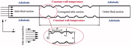
Table 1. Geometrical dimensions of the simulation tubes.
2.2. Governing equations
A three-dimensional CFD model is employed to investigate the flow and heat transfer characteristics in corrugated tubes. The Reynolds-averaged Navier–Stokes equations (RANS equations) and Reynolds Stress Model (RSM) based on Reynolds decomposition are numerically solved in ANSYS Fluent 14.5. This numerical computation method is also used to calculate turbulent flow and heat transfer in rotating rectangular channels as well as the turbulent round jet flow [Citation28,Citation29]. The governing equations are given below, and the validation of the model is presented in Section 3.1.
The following assumptions are adopted in this study: (a) property parameters of the working fluid (He) are considered as identical to those of an incompressible flow with constants as listed in ; and (b) the body force and radiation heat transfer are neglected [Citation30].
Table 2. Properties of working fluids.
The continuity equation is as follows:(1)
The momentum equation is as follows:(2)
The energy equation is stated as follows:(3) where E denotes the total energy,
and
denotes thermal conductivity, P denotes pressure.
The Reynolds stress transport equations (RSM) are expressed as follows [Citation31]:(4)
In EquationEq. (4)(4) , Cij denotes a convective term, and the terms on the right-hand side denotes the turbulent diffusion term, molecular viscous diffusion term, shear stress production term, stress–strain term, and viscosity dissipation term, in their order of appearance, respectively. The expressions are as follows:
(5)
(6)
(7)
(8)
(9)
(10)
In order to ensure that the numerical calculation is more stable, other forms of the DT,ij, Φij, and εij equations are employed as given below [Citation32]:(11) where
denotes the turbulent viscosity, and
[Citation32,Citation33]
(12) where ϕij,1 denotes the slow term that is also known as the return-to-isotropy term, and ϕij,2 denotes the rapid term. Additionally, ϕij,w denotes the surface reflection term although it is not considered here
(13)
(14) where C1 and C2 correspond to 1.8 and 0.6, respectively [Citation34].
With respect to the viscosity dissipation term, it is assumed that viscous dissipation is only produced in the small-scale vortex and that the large-scale vortex mainly undertakes momentum transport. Furthermore, the small-scale vortex is considered as isotropic, and therefore, εij is simplified as follows [Citation31]:(15)
2.3. Entropy generation analysis
The local entropy generation rate for a three-dimensional flow in Cartesian coordinates is given as follows [Citation25,Citation35]:(16)
(17)
(18) where λ denotes thermal conductivity, μ denotes dynamic viscosity, and Tf denotes bulk temperature of the fluid that is represented by the mean values of inlet and outlet. The total entropy generation rate integrates the local total entropy generation in the complete computational domain, and is similar to the total heat transfer and friction entropy generation rate as follows:
(19)
The local Bejan number (Belocal) is defined as the ratio between the local heat transfer entropy generation and the local total entropy generation. The local and the average Be are expressed as follows [Citation36], respectively:(20)
(21)
when Be > 0.5, it implies that the heat transfer irreversibility dominates; otherwise, flow friction irreversibility dominates.
2.4. Boundary conditions and solution methodology
The inlet condition consist of the velocity inlet condition with a fixed temperature (Tin = 663.15 K) and turbulence intensity (Iin = 5%). The outlet condition is a pressure outlet condition (Pout = 3 MPa) with a fixed backflow turbulence intensity (Iout = 5%) and backflow turbulence viscosity ratio Additionally, the hydraulic diameter of the tube corresponds to Din = 20 mm. The outside wall condition has a constant temperature (Twall = 603.15 K) boundary condition at the corrugated tube section and adiabatic condition at the inlet fluid and outlet fluid sections and coupled with a no-slip boundary condition on the inside wall.
2.5. Numerical method and grid independence study
A numerical steady-state simulation is considered to examine and solve the complex turbulent flow and heat transfer processes. The governing equations are discretized by using the finite volume method (FVM) and solved via a steady-state implicit format. The semi-implicit method for pressure-linked equations (SIMPLE) algorithm is used to couple velocity and pressure fields [Citation37].
A nonuniform structured grid [Citation38] is used in the geometrical model with a grid refinement near the interfaces as shown in . A grid independence study is performed for the HCT-1 under Re = 25,040. The results in indicate good stability with respect to the mesh numbers of 288,000 and 430,000. Hence, a total mesh number corresponding to 288,000 is employed.
Figure 2. Computational grid used in the numerical simulations.
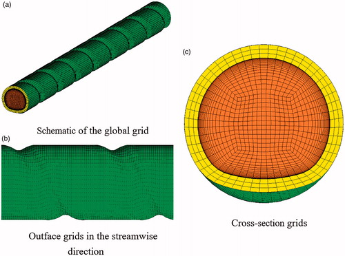
Table 3. Mesh independence test.
3. Results and discussion
3.1. Validation of the RSM and local entropy generation model
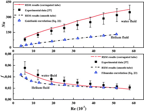
In order to validate the RSM, the average Nu and f for water flow in a helically corrugated tube and Helium gas flow in a smooth tube are predicted and compared with the experimental data [Citation39] and the Gnielinski and Filonenko empirical correlations for a smooth tube [Citation40], respectively. These are expressed as follows:(22)
(23)
The working fluid at the tube side corresponds to hot water with a temperature of 343 K, and a constant temperature of 301 K prevails outside the wall. The geometrical parameters are as follows: inner diameter, outer diameter, pitch-to diameter ratio, and rib-height to diameter ratio correspond to 26 mm, 28.5 mm, 0.27, and 0.04, respectively. As shown in , the comparisons indicate a good agreement between the RSM results and the empirical formulas for the smooth tube. With respect to the internal HCT, the maximum error between the RSM results and the experimental data is <20%, but the error increases with decreases in Re. This implies that the RSM is more accurate for high Re.
Figure 3. Validation of RSM with experimental data of inward helically corrugated tubes and empirical correlations of smooth tube.
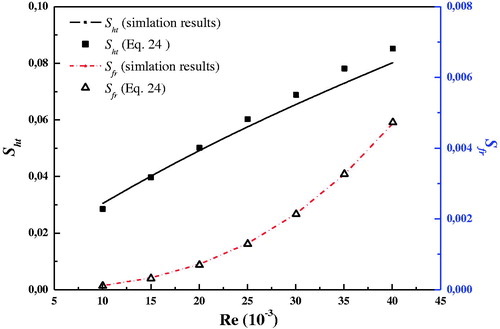
Bejan’s entropy generation formula EquationEq. (24)(24) [Citation41] is used to validate the local entropy generation model EquationEqs. (16)
(16) and Equation(18)
(18) . In the right-hand side of EquationEq. (24)
(24) , the first term is heat transfer entropy generation, and the second term is friction entropy generation. The expressions for the Nusselt number (Nu) and Darcy friction factor (f) [Citation42,Citation43] are given by EquationEqs. (25)
(25) and Equation(26)
(26) , respectively
(24)
(25)
(26) where q′ denotes average heat flux per unit tube length, λ denotes fluid thermal conductivity, ρ denotes fluid density, D denotes hydraulic diameter, m denotes mass flow rate, h denotes average heat transfer coefficient of the fluid, L denotes tube length, V denotes mean fluid velocity, and △P denotes the pressure drop between the inlet and outlet.
The results for the smooth tube with fixed temperature condition (Twall = 663.15 K) by the local entropy generation model and Bejan’s formula are shown in . The results indicate a good agreement, and the errors are within ±5%.
Figure 4. Validation of numerical entropy generation model with Bejan’s formula.
3.2. Flow pattern
In the helically corrugated tubes, a detached vortex is induced by the centrifugal forces at the corrugation leeside as shown in . The “AP” corresponds to the starting point of the adverse pressure gradient “SP” corresponds to the separation point
and “RP” corresponds to the reattachment point
[Citation44] of the detached vortex. Additionally, a spiral wake is also developed in the helically corrugated tubes and coupled with the secondary flow. The intensity of the turbulent fluctuation is given by the Turbulent Kinetic Energy (TKE) [Citation45] as follows:
(27)
Figure 5. Velocity vectors at the longitudinal section for the five cases (Re = 20,030).
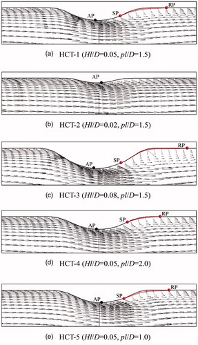
Three types of abnormal flow patterns, namely secondary flow, spiral flow, and turbulent fluctuation, are the main reasons for the enhanced heat transfer and flow resistance compared to the smooth flow. This section mainly focuses on the effect of geometrical parameters (corrugation height and pitch) on flow patterns. Five cases of velocity vectors considered in the longitudinal section are shown in . The results indicate that the intensity of the swirl flow decreases with decreasing Hl/D, and a secondary flow does not exist when Hl/D = 0.02. This is because the adverse pressure gradient is reduced due to the decrease in corrugation height, and the adverse pressure gradient is not sufficient to produce a secondary flow when the height reaches a limit. With increasing pl/D, the secondary flow slightly decreases.
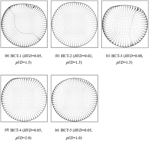
describes the velocity vectors at the crosssection (at the position of the line in ). It is observed that the fluid flow for all the five cases develops a circumferential velocity in HCTs, and this mainly appears at the straight wall zone. With increases in Hl/D, the intensity of the spiral wake significantly increases, and almost no rotational flow is present in the case of HCT-2. An increase in the pl/D slightly increases the rotational flow velocity maximum value although less fluid possesses circumferential velocity.
Figure 6. Velocity vectors at the cross section for the five cases (Re = 20,030).
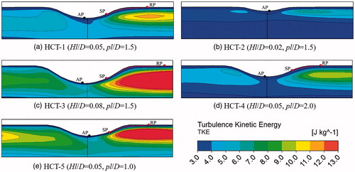
It is noted that the TKE significantly increases with decreases in Hl/D and pl/D in . This trend is similar to the intensity of the secondary flow. In the case of HCT-2, the turbulent fluctuation is very modest and similar to that of the smooth tube. This is because the fluid pulsation is mainly induced by the swirl flow at the corrugation leeside.
Figure 7. TKE distribution at the longitudinal section for the five cases (Re = 20,030).
3.3. Local entropy generation
show the local heat transfer, friction, and total entropy generation distribution for the five cases at Re = 20,030. As shown by EquationEqs. (17)(17) and Equation(18)
(18) , the local heat transfer and friction entropy generation are mainly computed by the temperature gradient and velocity gradient at the same fixed physical and boundary conditions. An increase in the temperature gradient indicates an increased heat transfer performance, and an increase in the velocity gradient implies an increased viscous dissipation. As shown in , the peak values of the local heat transfer entropy generation are mainly located at the boundary layer region because the temperature gradient significantly exceeds that in the mainflow region. Additionally, a high level of the local thermal entropy generation is also maintained in this area due to the secondary flow. Increases in Hl/D and the intensity of the secondary flow drive more fluid and improve the heat transfer among the internal fluids. However, the differences among the various cases of pl/D are very low although the frequency increases with decreasing pl/D.
Figure 8. Distribution of the local heat transfer entropy generation rate for the five cases (Re = 20,030).
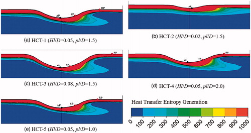
Figure 9. Distribution of the local friction entropy generation rate for the five cases (Re = 20,030).
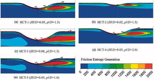
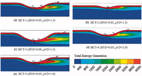
Figure 10. Distribution of the local total entropy generation rate for the five cases (Re = 20,030).
The local friction entropy generation is evidently observed at the region of violent turbulent pulsation, and at the windward of the corrugation in which the fluid impacts on the walls in . Increases in Hl/D significantly improve the fluid friction irreversibility, and the friction irreversibility decreases slightly with increases in pl/D. The trend and location of the local friction entropy generation are identical to the distribution of TKE, and this indicates that severe turbulent pulsations cause serious viscous dissipation, although it is affected by the increased spiral wake.
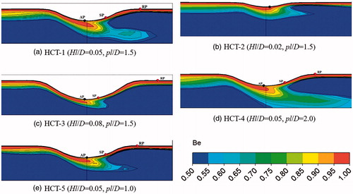
The local total entropy generation is shown in , and this is the sum of local heat transfer and friction entropy generation and possesses both features. The local Be is shown in to describe the share of the local thermal entropy generation. It is observed that the heat transfer entropy generation dominant region (effective heat transfer zone) is only in the sub-layer, buffer layer, and a tail-shaped area from the “AP”. With respect to increases in Hl/D, the effective heat transfer zone presents for peak value at the case of HCT-1. In the case of the highest Hl/D, that is, case HCT-3, the local friction entropy generation is significantly improved, although it presents a higher local heat transfer entropy generation. With increases in pl/D, the effective heat transfer zones indicate evident growth because the low frequency corrugation slightly influences the local heat transfer entropy generation while it significantly reduces the local friction entropy generation.
Figure 11. Distribution of local Be for the five cases (Re = 20,030).
3.4. Average entropy generation
The average heat transfer, friction, total entropy generations (Sht, Sfr, Stot), and Bejan number (Beave) for the helically corrugated tubes and smooth tube are shown in and . It is observed that both Sht and Sfr increase with increasing Re and Hl/D and decreasing pl/D. However, the growth rate of Sfr significantly exceeds Sht. Specifically, for increases in Re, Sfr exhibits an exponential growth, while Sht only exhibits linear growth. The Stot also exhibits a linear growth with increasing Re, and the Beave displays an exponential decrease and its minimum value reaches 0.69.
Figure 12. Variation of average heat transfer and friction entropy generation for different pl/D and Hl/D.
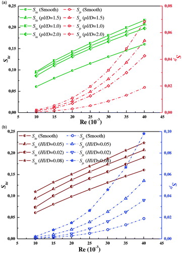
Figure 13. Variation of average total entropy generation and Be for different pl/D and Hl/D.
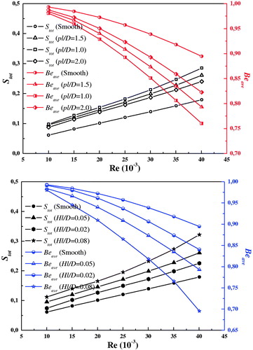
With decreasing pl/D, the Sht exhibits slight improvements but the increases in Sfr are relatively moderate. However, the Hl/D significantly influences the entropy generation. With respect to the case of Hl/D = 0.08, the increase in Sfr is significantly deteriorated for the complete range of Re. From a comprehensive perspective, the optimal Re is approximately 25,040 but does not exceed 30,050. With respect to low Re values, corrugated tubes with increasing roughness are also available. However, corrugations with high roughness are not recommended for high Re values and especially the case of Hl/D = 0.08.
4. Conclusions
In this study, entropy generation analysis of fully-developed turbulent heat transfer flow in inward helically corrugated tubes is numerically investigated. The validation of an RSM and a local entropy generation model is carried out by comparisons with experimental data and empirical formulae and good agreement is found. The detached vortex and spiral wake are induced by the centrifugal forces and frictional action in the corrugated tubes, and the spiral flow displays an inhibitory action to the turbulent fluctuation. The peak values of local heat transfer entropy generation are mainly located at the boundary layer region and the secondary flow region, while the peak values of local friction entropy generation are mainly located at the windward of the corrugation and the severely turbulent pulsation region. The Sfr exhibits an exponential growth, while the Sht and Stot exhibit a linear growth trend with increasing Re. The Beave is characterized by an exponential fall and the minimum value reaches 0.69. From an overall viewpoint, the optimal Re is approximately 25,040 but does not exceed 30,050. With respect to low Re values, corrugated tubes with increasing roughness are also available. However, corrugations with high roughness are not recommended for high Re values, especially the case of Hl/D = 0.08.
Additional information
Funding
References
- O. Manca, S. Nardini, and D. Ricci, “Numerical analysis of water forced convection in channels with differently shaped transverse ribs,” J. Appl. Math., vol. 2011, pp. 1–25, 2011. http://dx.doi.org/10.1155/2011/323485
- P. Naphon, M. Nuchjapo, and J. Kurujareon, “Tube side heat transfer coefficient and friction factor characteristics of horizontal tubes with helical rib,” Energ. Convers. Manage., vol. 47, pp. 3031–3044, 2006. https://doi.org/10.1016/j.enconman.2006.03.023
- S. Rozzi et al., “Heat treatment of fluid foods in a shell and tube heat exchanger: comparison between smooth and helically corrugated wall tubes,” J. Food Eng., vol. 79, pp. 249–254, 2007. https://doi.org/10.1016/j.jfoodeng.2006.01.050
- H. A. Mohammed, A. K. Abbas, and J. M. Sheriff, “Influence of geometrical parameters and forced convective heat transfer in transversely corrugated circular tubes,” Int. Commun. Heat Mass Transf., vol. 44, pp. 116–126, 2013. http://dx.doi.org/10.1016/j.icheatmasstransfer.2013.02.005
- A. Harleß, E. Franz, and M. Breuer, “Heat transfer and friction characteristics of fully developed gas flow in cross-corrugated tubes,” Int. J. Heat Mass Transf., vol. 107, pp. 1076–1084, 2017. http://dx.doi.org/10.1016/j.ijheatmasstransfer.2016.10.129
- K. S. Lee, W. S. Kim, and J. M. Si, “Optimal shape and arrangement of staggered pins in the channel of a plate heat exchanger.” Int. J. Heat Mass Transf., vol. 44, pp. 3223–3231, 2001. https://doi.org/10.1016/S0017-9310(00)00350-1
- J. Liu, G. N. Xie, and W. S. Terrence, “Turbulent flow and heat transfer enhancement in rectangular channels with novel cylindrical grooves,” Int. J. Heat Mass Transf., vol. 81, pp. 563–577, 2015. https://doi.org/10.1016/j.ijheatmasstransfer.2014.10.021
- S. Chamoli, P. Yu, and K. Alok, “Multi-response optimization of geometric and flow parameters in a heat exchanger tube with perforated disk inserts by Taguchi grey relational analysis,” Appl. Therm. Eng., vol. 103, pp. 1339–1350, 2016. https://doi.org/10.1016/j.applthermaleng.2016.04.166
- V. Zimparov, “Enhancement of heat transfer by a combination of a single-start spirally corrugated tubes with a twisted tape,” Exp. Therm. Fluid Sci., vol. 25, pp. 535–546, 2002. https://doi.org/10.1016/S0894-1777(01)00112-1
- E. Jalil and Goudarzi K., “Experimental study of heat transfer enhancement in the evaporator of single-effect absorption chiller using new different tube insert,” Appl. Therm. Eng., vol. 128, pp. 1–9, 2018. https://doi.org/10.1016/j.applthermaleng.2017.09.004
- O. E. Ivashnyov and N. N. Smirnov, “Thermal growth of a vapor bubble moving in superheated liquid,” Phys. Fluids, vol. 16, pp. 809–823, 2004. https://doi.org/10.1063/1.1645851
- S. M. Demsky and H. B. Ma, “Thin film evaporation on a curved surface,” Microscale Thermophys. Eng., vol. 8, pp. 285–299, 2004. https://doi.org/10.1080/10893950490477590
- W. Zan, B. Sundén, V. V. Wadekar, and W. Li, “Heat transfer correlations for single-phase flow, condensation, and boiling in microfin tubes,” Heat Transf. Eng., vol. 36, pp. 582–595, 2015. https://doi.org/10.1080/01457632.2014.939531
- P. K. Namburu, D. K. Das, K. M. Tanguturi, and R. S. Vaijha, “Numerical study of turbulent flow and heat transfer characteristics of nanofluids considering variable properties,” Int. J. Therm. Sci., vol. 48, pp. 290–302, 2009. https://doi.org/10.1016/j.ijthermalsci.2008.01.001
- K. Wongcharee and S. Eiamsa-ard, “Heat transfer enhancement by using CuO/water nanofluid in corrugated tube equipped with twisted tape,” Int. Commun. Heat Mass Transf., vol. 39, pp. 251–257, 2012. https://doi.org/10.1016/j.icheatmasstransfer.2011.11.010
- W. Zan and B. Sundén, “Convective heat transfer performance of aggregate-laden nanofludis,” Int. J. Heat Mass Transf., vol. 93, pp. 1107–1115, 2016. https://doi.org/10.1016/j.ijheatmasstransfer.2015.11.032
- H. Sadek, A. J. Robinson, and J. S. Cotton, “Electrohydrodynamic enhancement of in-tube convective condensation heat transfer,” Int. J. Heat Mass Transf., vol. 49, pp. 1647–1657, 2006. https://doi.org/10.1016/j.ijheatmasstransfer.2005.10.030
- F. Zamzari, Z. Mehrez, and A. E. Cafsi, “Numerical investigation of entropy generation and heat transfer of pulsating flow in a horizontal channel with an open cavity,” J. Hydrodyn., vol. 29, pp. 632–646, 2017. https://doi.org/10.1016/S1001-6058(16)60776-X
- R. Azizian et al., “Effect of magnetic field on laminar convective heat transfer of magnetite nanofluids,” Int. J. Heat Mass Transf., vol. 68, pp. 94–109, 2014. https://doi.org/10.1016/j.ijheatmasstransfer.2013.09.011
- X. Su, X. Chen, and J. Liu, “Experimental investigation of forced flow boiling of nitrogen in a horizontal corrugated stainless steel tube,” Cryogenics, vol. 70, pp. 47–56, 2015. https://doi.org/10.1016/j.cryogenics.2015.05.001
- W. Wang, Y. N. Zhang, and B. X. Li, “Influence of geometrical parameters on turbulent flow and heat transfer characteristics in outward helically corrugated tubes,” Energ. Convers. Manage., vol. 135, pp. 294–306, 2017. https://doi.org/10.1016/j.enconman.2017.01.029
- J. Liu et al., “Heat transfer enhancement and turbulent flow in a high aspect ratio channel (4:1) with ribs of various truncation types and arrangements,” Int. J. Therm. Sci., vol. 123, pp. 99–115, 2018. https://doi.org/10.1016/j.ijthermalsci.2017.09.013
- G. Xu and Z. B. Zhang, “Experimental investigation of the applied performance of several typical enhanced tubes,” J. Enhanc. Heat Transf., vol. 17, pp. 331–341, 2010. doi:10.1615/JEnhHeatTransf.v17.i4.40
- J. Vicente, A. Garcia, and A. Viedma, “Experimental investigation on heat transfer and frictional characteristics of spirally corrugated tubes in turbulent flow at different Prandtl numbers,” Int. J. Heat Mass Transf., vol. 47, pp. 671–681, 2004. https://doi.org/10.1016/j.ijheatmasstransfer.2003.08.005
- Y. Ji, H. C. Zhang, X. Yang, and L. Shi, “Entropy generation analysis and performance evaluation of turbulent forced convective heat transfer to nanofluids,” Entropy, vol. 19, pp. 1–18, 2017. https://doi.org/10.3390/e19030108
- X. J. Zhu, X. Du, Y. Ding, and Q. Qiu, “Analysis of entropy generation behavior of supercritical water flow in a hexagon rod bundle,” Int. J. Heat Mass Transf., vol. 114, pp. 20–30, 2017. https://doi.org/10.1016/j.ijheatmasstransfer.2017.06.047
- J. A. Esfahani, and P. B. Shahabi, “Effect of non-uniform heating on entropy generation for the laminar developing pipe flow of a high Prandtl number fluid,” Energ. Convers. Manage., vol. 51, pp. 2087–2097, 2010. https://doi.org/10.1016/j.enconman.2010.02.022
- G. Su, H. C. Chen and J. C. Han, “Computation of flow and heat transfer in rotating rectangular channels (AR =4:1) with Pin-Fins by a Reynolds Stress Turbulence Model.” J. Heat Transf., vol. 129, pp. 685–696, 2007. doi:10.1115/1.2717935
- A. Amamou, S. Habli, and N. M. Said, “Numerical study of turbulent round jet in a uniform counterflow using a second order Reynolds Stress Model,” J. Hydro-environ. Res., vol. 9, pp. 482–495, 2015. https://doi.org/10.1016/j.jher.2015.04.004
- J. Zhang, J. He, L. Zhou, and S. Nieh , “Simulation of swirling turbulent heat transfer in a vortex heat exchanger,” Numer. Heat Transf A-Appl., vol. 48, pp. 607–625, 2005. https://doi.org/10.1080/10407780590960031
- Fluent Inc., FLUENT User’s Guide. New Hampshire, USA: Fluent Inc., 2003.
- S. Fu, B. E. Launder and M. A. Leschziner, “Modeling strongly swirling recirculating jet flow with Reynolds-stress transport closures.” In Sixth Symposium on Turbulent Shear Flows. Toulouse, France, 1987.
- F. S. Lien and M. A. Leschziner, “Assessment of turbulent transport models including non-linear RNG eddy-viscosity formulation and second-moment closure. Comput. Fluids, vol. 23, pp. 983–1004, 1994. https://doi.org/10.1016/0045-7930(94)90001-9
- M. M. Gibson and B. E. Launder, “Ground effects on pressure fluctuations in the atmospheric boundary layer.” J. Fluid Mech., vol. 86, pp. 491–511, 1978. https://doi.org/10.1017/S0022112078001251
- A. Bejan, “A study of entropy generation in fundamental convective heat transfer,” J. Heat Transf., vol. 101, pp. 718–725, 1979. doi:10.1115/1.3451063
- P. Biswal and T. Basak, “Analysis of exergy loss vs heat transfer rate for Rayleigh–Benard convection of various fluids in enclosures with curved walls,” Numer. Heat Transf. A-Appl., vol. 11, pp. 461–476, 1987. https://doi.org/10.1080/10407782.2017.1412223
- W. Wang, Y. N. Zhang, and B. X. Li, “Numerical investigation of tube-side fully developed turbulent flow and heat transfer in outward corrugated tubes,” Int. J. Heat Mass Transf., vol. 116, pp. 115–126, 2018. https://doi.org/10.1016/j.ijheatmasstransfer.2017.09.003
- L. Langellotto, O. Manca, and S. Nardini, “Numerical investigation of transient natural convection in air in a convergent vertical channel symmetrically heated at uniform heat flux,” Numer. Heat Transf A-Appl., vol. 51, pp. 1065–1086, 2007. https://doi.org/10.1080/10407790601184355
- S. Pethkool, S. Eiamsa-ard, S. Kwankaomeng, and P. Promvonge, “Turbulent heat transfer enhancement in a heat exchanger using helically corrugated tube.” Int. Commun. Heat Mass Transf., vol. 38, pp. 340–347, 2011. https://doi.org/10.1016/j.icheatmasstransfer.2010.11.014
- V. Ozceyhan, S. Gunes, O. Buyukalaca, and N. Altuntop, “Heat transfer enhancement in a tube using circular cross sectional rings separated from wall,” Appl. Energ., vol. 85, pp. 988–1001, 2008. https://doi.org/10.1016/j.apenergy.2008.02.007
- A. Bejan, “Entropy generation minimization: the new thermodynamics of finite-size devices and finite-time processes,” Appl. Phys., vol. 19, pp. 1191–1218, 1996. https://doi.org/10.1063/1.362674
- Z. Cao, Z. Wu, H. Luan, and B. Sundén, “Numerical study on heat transfer enhancement for laminar flow in a tube with mesh conical frustum inserts,” Numer. Heat Transf. A-Appl., vol. 72, pp. 21–39, 2017. https://doi.org/10.1080/10407782.2017.1353386
- G. Xie, Y. Song, and T. W. Simon, “Turbulent flow characteristics and heat transfer enhancement in a rectangular channel with elliptical cylinders and protrusions of various heights,” Numer. Heat Transf. A-Appl., vol. 72, pp. 417–432, 2017. https://doi.org/10.1080/10407782.2017.1386507
- L. Eric, S. Jorge, and L.Sylvain, “Direct numerical simulation of a separation bubble on a rounded finite-width leading edge,” Int. J. Heat Fluid Fl., vol. 29, pp. 612–625, 2008. https://doi.org/10.1016/j.ijheatfluidflow.2008.03.006
- B. E. Launder and D. B. Spalding, “The numerical computation of turbulent flows,” Comput. Method. Appl. Mech. Eng., vol. 3, pp. 269–289, 1974. https://doi.org/10.1016/B978-0-08-030937-8.50016-7