
ABSTRACT
In modern gas turbine engines, the first stage vane endwall endures high thermal load with the increase of the turbine inlet temperature and the uniformity of the temperature distribution at combustor outlet. Moreover, the endwall secondary flow forces the coolant flow toward the suction side, resulting in hot regions along the pressure side endwall. In the worst case, hot regions lead to thermal failure. In order to ensure that the gas turbine operates safely, advanced cooling techniques are urgently needed to be implemented to reduce the hot regions along the pressure side endwall. In the current research, the influences of the pressure side injection slot on the film cooling performance of the endwall surface were numerically investigated. The three-dimensional Reynolds-averaged Navier-Stokes (RANS) equations combined with the shear stress transport (SST) turbulence model were solved to conduct the simulations. Cases with different injection slot configurations have been simulated. The results indicate that the hot region along the pressure side endwall is significantly reduced by introducing the pressure side injection slot. The coolant from the pressure side injection slot is assisted by the pressure side vertical flow toward the adjacent vane suction side. Therefore, the coolant coverage and the cooling effectiveness are increased. In this study, the expanded slot (ES) achieves a larger cooling effectiveness than the normal slot (NS) and convergent slot (CS) at a small blowing ratio M = 0.5. In contrast, the CS obtains a larger cooling effectiveness than the NS and ES at M = 1.0 and M = 1.5. In addition, the introduction of the pressure side injection slot has a small influence on the aerodynamic performance of the vane cascade.
1. Introduction
The significant increases in the energy demand all over the world and strict regulations on NOx emission have become great challenges for the worldwide sustainable development. In order to resolve those problems, designers increase the turbine inlet temperature to obtain a higher level of thermal efficiency to minimize the CO2 emission. Furthermore, the combustor is designed to generate a flat pattern temperature distribution to decrease the production of NOx. As a result, the temperature near the endwall is significantly increased and the local temperature is higher than the melting point of the presently available turbine manufacturing material. To achieve improved reliability of gas turbine operation, advanced cooling technologies are urgently required to be applied to the first stage vane endwall. Actually, the intensified turbulent flow from the combustor and complex secondary flow make the first stage vane endwall cooling difficult. In the worst case, severe thermal failures occur [Citation1]. Consequently, first stage vane endwall cooling is a key part among all cooling schemes and requires further studies.
Film cooling, as an effective cooling technique, has been widely implemented in gas turbine cooling systems. Numerous studies concerning the film cooling technology have been conducted in the past few decades. Some reviews about the cooling performance on the platform and endwall surface have been presented by Han et al. [Citation2], Simon and Piggush [Citation3]. Friedrichs et al. [Citation4,Citation5] investigated the film cooling effectiveness of the endwall surface to reveal the mechanism of the endwall film cooling in a real vane cascade. They found that the pressure difference had a significant effect on the distribution of the coolant coverage. Bunker [Citation6] published a review regarding the shaped hole film cooling performance in a gas turbine. He indicated that geometric parameters had a significant influence on the endwall cooling effectiveness, and developing novel shaped holes was still an important way to increase the cooling effectiveness. The study by Gao et al. [Citation7] indicated that shaped holes presented a higher cooling effectiveness and wider coolant coverage on the blade platform than normal cylindrical holes, especially at higher blowing ratios. They found that the shaped hole contributed to enhance the lateral expansion of the coolant jet, resulting in larger coolant coverage. Yang et al. [Citation8] compared the cooling performance among four different film hole geometries. The results showed that the bean-shaped hole achieved the best cooling performance on the endwall in comparison to the normal cylindrical hole and other novel shaped holes due to the larger expansion of the coolant coverage in the lateral direction. In addition, the layout of the film holes has a significant effect on the coolant distribution; hence, it affects the distribution of the endwall cooling effectiveness. Moreover, Wang et al. [Citation9] investigated the effects of deposition near the film holes on the endwall film cooling performance. They found that the cooling effectiveness can be reduced with the increase of the deposition height and width. In addition, Du et al. [Citation10] investigated the influence of the film hole row layout near the vane leading edge on the endwall cooling performance. The leading edge film hole toward the upstream direction achieved a relatively higher level of endwall cooling effectiveness near the vane leading edge due to the assistance of the vortical flow near the leading edge. Lee and Kim [Citation11] investigated the influence of the trench shapes and the blowing ratio on the endwall cooling performance. They found that the inclination of the film holes toward trench can significantly increase the endwall cooling effectiveness.
In turbine industry, a real gas turbine is assembled by many components. Therefore, gaps are inevitable between different parts. One of the most important interfaces is the upstream slot between the combustor outlet and turbine inlet. To avoid hot gas ingestion, the upstream slot is filled up with the high-pressure coolant from the compressor. This coolant jet can be effectively used to achieve cooling benefit to the forward region, even to the further downstream region. A number of studies have been released concerning the cooling performance of the upstream slot. Blair [Citation12] was the first to investigate the influences of the upstream slot on the endwall cooling performance. The cooling effectiveness on the endwall showed a significant variation along the pitch-wise direction, and a large portion of the coolant moved toward the vane suction side surface, resulting in a hot region along the pressure side. He also concluded that the downstream cooling effectiveness was enhanced with increasing coolant mass flow rate. Pasinato et al. [Citation13] indicated that the lateral pressure difference drives the coolant flow from the upstream slot toward the suction side and the heat transfer near the leading edge was decreased in comparison with the case without upstream slot coolant.
Above studies indicate that the complicated vortex near the leading edge also has a significant influence on the endwall cooling performance. In contrast, the coolant jet from the upstream slot also alters the vortex distribution near the vane leading edge. The study by Nicklas [Citation14] showed that the horseshoe vortex was enhanced without the film holes as a part of the coolant jet from the upstream slot was lifted off the endwall. Consequently, a portion of the coolant jet is lifted off the endwall by the enhanced horseshoe vortex instead of cooling the endwall surface.
In order to reduce the influence of the horseshoe vortex, film holes are introduced near the leading edge. Hence, the upstream slot and the leading edge film hole are combined to increase the endwall cooling effectiveness. Cardwell et al. [Citation15,Citation16] investigated the influence of the upstream slot width and the endwall alignment on the endwall cooling performance. The results showed that the endwall cooling effectiveness was increased when the width of the upstream slot was decreased. This is because the momentum of the coolant jet is increased as the width of the upstream slot is decreased. Furthermore, endwall cooling is significantly affected by the endwall alignment. Increasing the height of the suction side endwall contributes to enhance the endwall cooling effectiveness. However, many studies indicate that the regions around the leading edge and along the pressure side still endure high level of thermal load even if an upstream slot and film holes have been implemented to increase the endwall cooling effectiveness. In terms of the hot regions in the endwall, Du and Li [Citation17] proposed a novel upstream slot configuration to increase the endwall cooling effectiveness. A fillet is introduced in the upstream slot and the downstream endwall junction. The results showed that the novel upstream slot significantly reduced the separation of the coolant jet relative to the sharp-edged slot. Therefore, more uniform coolant distribution was achieved and the endwall cooling effectiveness was remarkably increased. Experiment by Knost and Thole [Citation18] showed that the variation of the pressure at the upstream slot outlet resulted in a non-uniform coolant distribution. This enhanced the non-uniform coolant coverage under the effect of lateral flow. In order to obtain a uniform coolant distribution at the upstream slot outlet, Du et al. [Citation19] developed a shaped upstream slot. For the shaped upstream slot, the area of the upstream slot presents a direct correlation with the pressure to rearrange the coolant mass flow rate at the slot outlet. As a result, the coolant tends to be more uniform at the slot outlet and the overall downstream endwall cooling effectiveness increases significantly. Moreover, endwall profiling is widely used to improve the aerothermal performance of the endwall. Kianpour et al. [Citation20] investigated film-cooling performance of the row trenched cooling holes. They found that the trenched cooling holes doubled the downstream endwall film-cooling effectiveness. More importantly, the hot regions near the leading edge and along the pressure side still exist in all above studies, and the presence of the hot regions is a serious threat to the gas turbine operation. To completely remove the hot region around the leading edge, Du et al. [Citation21] proposed a leading edge injection slot, introducing the coolant jet from the root of the vane. The results indicated that the hot region near the leading edge was totally removed due to the effective cooling by the coolant jet from the leading edge injection slot.
As shown above, the pressure side hot region endures high level of thermal load and needs advanced cooling schemes to ensure the safe operation [Citation16,Citation17]. Chowdhury et al. [Citation22] introduced two rows of film holes near the pressure side. The experimental results showed that the typical uncooled region was reduced. The coolant jet from the pressure side film holes was driven by the lateral flow; hence the coolant coverage was expanded toward the lateral direction. Moreover, the cooling coverage was enlarged with the increase of the coolant mass flow rate. Du et al. [Citation23] indicated that the direction of the upstream slot coolant had a significant influence on the downstream endwall cooling effectiveness, especially along the pressure side. The results showed that the endwall cooling effectiveness was enhanced when the upstream slot coolant was ejected toward the pressure side due to the increasing momentum opposite to the lateral flow in the passage. The coolant jet ejected toward the vane pressure side has a larger momentum to reach the pressure side endwall relative to the baseline case. Therefore, the pressure side hot region is reduced. In addition, Takeishi et al. [Citation24,Citation25] introduced a swirling coolant jet to the endwall cooling system. They found that the swirling coolant jet spread wider in the pitch-wise direction downstream for the shaped-hole. The laterally averaged film cooling effectiveness of the downstream region was 50% higher than that in the non-swirling case. Thus, they implemented the swirling coolant flow at the vane endwall along the pressure side. A higher film cooling effectiveness level was obtained at the pressure side endwall relative to the conventional case.
Although many studies have been conducted to enhance the endwall cooling effectiveness, the region along the vane pressure side still obtains a relatively low level of cooling effectiveness due to the presence of the lateral flow in the vane passage [Citation15,Citation21]. Therefore, the primary issue of interest in this study concerns the effects of the pressure side injection slot on increasing the pressure side endwall cooling effectiveness.
2. Numerical modeling and methods
2.1. Geometry and boundary conditions
A conventional vane cascade described by Du and Li [Citation17] is considered in this study. The layout of the vane cascade is shown in . All parameters and boundary conditions are the same as in the experiment [Citation16]. shows the cooling schemes and the vanes from the top view. The cooling schemes include upstream slot, film holes, and pressure side injection slot. In this study, the filleted junction of the upstream slot was utilized due to the superior cooling performance [Citation17]. illustrates the upstream slot with downstream fillet and film holes from the side view. The inclined angles for the upstream slot and the film holes in this study are specified as 45 and 30°, respectively. Furthermore, the constant mass flow rates of the upstream slot and the film holes are defined according to the experiment [Citation16]. In addition, the diameter of the film hole near the leading edge is, D = 4.6 mm and all length variables are normalized by D. In this study, all geometric and flow conditions are presented in .
Figure 1. Layout of the cascade with the endwall cooling configuration (a) Top to down view of the normal cascade; (b) The side view of the normal case.
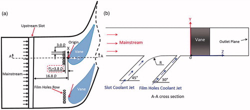
Table 1. Geometric and flow conditions
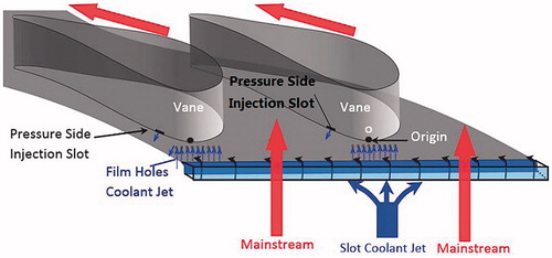
shows an overview of the vane cascade with the cooling system. The first stage vane endwall is jointly cooled by three portions of the coolant jet as shown in . A pressure side injection slot is proposed in this study to enhance the cooling effectiveness near the vane pressure side. A part of the coolant extracted from the compressor flows through this injection slot and enters the mainstream, contributing to increasing the cooling effectiveness on the pressure side endwall surface.
Figure 2. Overview of the cascade with endwall cooling configurations.
2.2. Mesh and solver description
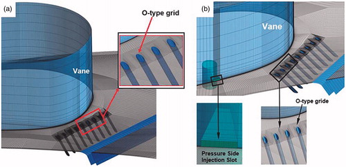
In this study, the commercial software ANSYS ICEM CFD version 17.0 (ANSYS, Inc., Canonsburg, PA) is used to generate the structured hexahedral mesh for the computational domain, involving the vane cascade passage, and cooling schemes. In terms of the unique topology for the simulated domain, an H-type grid is used for the vane cascade passage, an O-type grid is utilized around the vane surface, and film holes to obtain a high-level mesh. In order to obtain a fine mesh near the wall, 40 layers, and 20 layers of grids in the O-type block are defined around the vane surface and the film holes, respectively. Moreover, 120 and 80 nodes are inserted along the span-wise orientation and the width of the upstream slot. The mesh of the baseline case without the pressure side injection slot is shown in . The mesh of the case with the pressure side injection slot is illustrated in . A total amount of 9.6 × 10⁶ cells are utilized in the numerical simulations. The thickness of the first cell near the endwall and vane surface is refined to ensure due to the requirement of the turbulence model. In addition, the simulated domain is composed of a single vane passage with periodic boundary conditions. In order to enhance the simulation accuracy, the nodes at the interfaces of the simulated domain are periodically matched (1:1).
Figure 3. Mesh of the cascade with and without pressure injection slot (a) Normal case without pressure side injection slot; (b) The case with pressure side injection slot.
In order to obtain more details of the computational domain and ensure the convergence of the calculations, the inlet and outlet boundaries are located at a distance of 1.0 axial chord upstream of the leading edge and a distance of 1.5 axial chords downstream of the trailing edge, respectively. In addition, the absolute total pressure and the absolute total temperature conditions are specified at the inlet plane. The averaged static pressure is defined at the outlet plane.
In this study, the commercial code ANSYS-CFX was utilized and the Reynolds-averaged Navier–Stokes equations were solved. The governing equations of continuity, energy, and momentum were discretized in time for steady calculations. Moreover, ANSYS CFX version17.0 uses an element-based finite volume method in the spatial discretization of the governing equations. A point implicit linear equation solver in conjunction with an algebraic multigrid method and a velocity-pressure coupling algorithm was utilized to avoid the decoupling. In addition, the second order advection scheme is adopted. Air as ideal gas is assumed as the fluid in the calculations. lists the details of the numerical method in this study.
Table 2. Numerical method
2.3. Turbulence model selection
This section aims to present the significance in selecting the optimal turbulence model for the numerical simulations. This is because the turbulence model is of significant importance for a numerical simulation using the RANS method. Therefore, the CFD method must be validated before being used in the numerical simulations. For the same vane profile and boundary conditions, Du and Li [Citation17] compared the numerical results obtained using four different typical turbulence models with experimental results [Citation15] to determine the most proper one. The detailed comparisons were illustrated in that study [Citation17]. The adiabatic cooling effectiveness is defined as:
(1) where
is the mainstream temperature,
and
are the adiabatic wall temperature and coolant jet temperature, respectively.
(2) where
,
and
,
are the density and velocity of the coolant jet and the mainstream, respectively.
In the numerical simulations, all boundary conditions are the same as in the experiment [Citation15]. The blowing ratios of the upstream slot and film holes are and
, respectively. The validation has been conducted in study [Citation17]. From the comparison, Du and Li [Citation17] found that the SST
turbulence model achieved the best accuracy in terms of the endwall cooling effectiveness distribution among all the investigated turbulence models. Consequently, the SST
turbulence model was utilized for all simulations in the present study as well.
2.4. Grid independence
In order to minimize the computing resources and obtain accurate numerical results, the grid independence was investigated in this section. A grid independence study for the baseline case as described in the experiment [Citation16] with different meshes 4.5 × 10⁶, 7.0 × 10⁶, 9.0 × 10⁶, and 1.1 × 10⁷ was conducted. In all cases, the mesh is refined to ensure that the for the first grid distance away from the endwall according to the requirement of the SST
turbulence model. The mesh nodes were adjusted synchronously at the same stretching ratio in three coordinate directions. The area-averaged cooling effectiveness of the region near the vane leading edge as illustrated in are listed in for different meshes. The case with total number of nodes equal to 9.0 × 10⁶ predicts the endwall cooling effectiveness accurately. Furthermore, a further refinement of the mesh has a marginal influence on the endwall cooling effectiveness near the vane leading edge. In terms of the computing time and the prediction accuracy, 9.6 × 10⁶ nodes including the mesh of the pressure side injection slot were selected for the final simulations in this study.
Figure 4. Cooling performance and flow field near of the endwall surface (a) Cooling effectiveness on endwall; (b) Flow streamlines near the endwall.
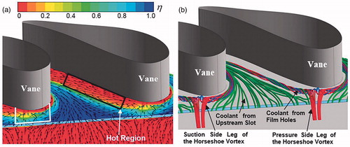
Table 3. Area-averaged cooling effectiveness near the vane leading edge
3. Results and discussions
3.1. Vane endwall cooling performance without pressure side injection slot
illustrates the adiabatic cooling effectiveness on the endwall surface and the flow structure adjacent to the endwall for the baseline case without the pressure side injection slot. shows that large regions around the leading edge and along the pressure side to obtain a relatively small cooling effectiveness compared with other regions on the endwall. indicates that the horseshoe vortex dominates the flow field near the leading edge. Most of the upstream coolant jet is limited within the region between the pressure side leg and suction side leg of the horseshoe vortex. This is because a portion of the coolant jet from the film holes is lifted off the endwall surface and a part of the coolant jet near the vane pressure side is driven by the lateral pressure difference toward the suction side. Therefore, the pressure side endwall surface is exposed to the hot gas, resulting in hot regions along the pressure side. The hot regions endure high level of thermal load, which is a significant threat to the gas turbine operation. Consequently, this study aims to increase the pressure side endwall cooling effectiveness by introducing a pressure side injection slot at the root of the first stage guide vane.
3.2. Vane endwall cooling performance with pressure side injection slot
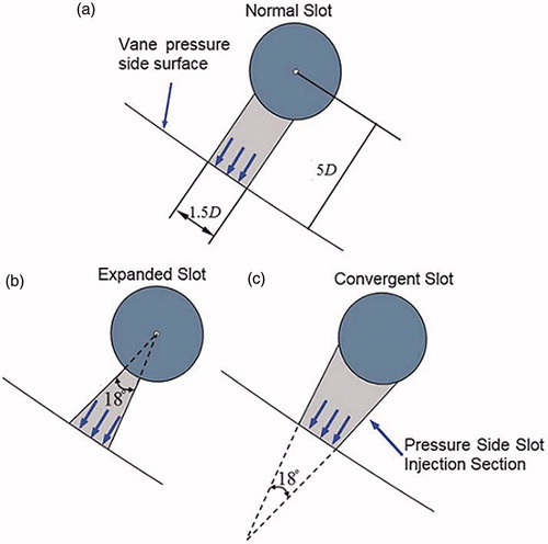
Three pressure side injection slot configurations are selected to investigate the cooling effectiveness on the endwall surface. illustrates three different pressure side injection slot configurations from the top to down view. shows the normal slot (NS) configuration. In this case, the coolant is ejected through a tube with a constant cross-sectional area. presents the expanded slot (ES) configuration. The coolant flow is ejected through a tube with an increasing cross sectional area. Moreover, the angle between the two lateral faces is 18° as shown in . illustrates the convergent slot (CS) configuration. The cross-sectional area is decreased along the coolant flow direction. For all cases, the width of the pressure side slot is defined as a constant 1.5D and the height of the pressure side injection slot is 0.5D.
Figure 5. Three pressure side injection slot from the top view (a) Normal slot; (b) Expanded slot; (c) Convergent slot.
presents the adiabatic cooling effectiveness on the endwall surface. Compared with the baseline case, a significant increase of the cooling effectiveness is observed for the case with the pressure side injection slot, especially for NS and CS with a large blowing ratio. For the cases with a NS and a CS, the coolant coverage is gradually enhanced with the increase of blowing ratio. However, the cases with an ES show totally different variations of the pressure side endwall cooling effectiveness when the blowing ratio of the pressure side injection slot is increased.
Figure 6. Adiabatic cooling effectiveness on the endwall surface.
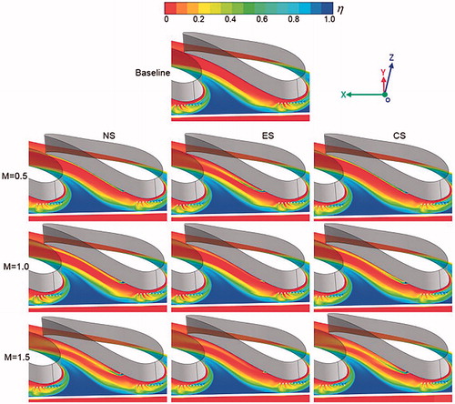
For the NS and CS, the coolant is closely located near the pressure side for M = 0.5. With the increase of the blowing ratio, the coolant becomes away from the vane pressure side surface due to the increase of the coolant momentum. Consequently, the coolant coverage is enlarged with increase of the pressure side slot-blowing ratio. Most importantly, the coolant achieves a relatively large lateral expansion with M = 1.5 when the coolant is driven by the pressure side vertical flow. In contrast, the case with the ES obtains the largest coolant coverage. However, the ES shows a decrease of coolant coverage when the blowing ratio increases from M = 0.5 to M = 1.0. On the other hand, the coolant coverage shows a small increase when the blowing ratio increases from M = 1.0 to M = 1.5.
In addition, all results show that the pressure side injection coolant mainly contributes to increasing the cooling effectiveness along the vane pressure side. Nevertheless, it has no influence on other regions of the endwall surface.
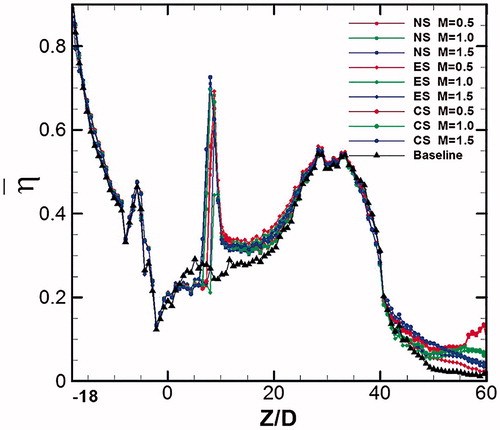
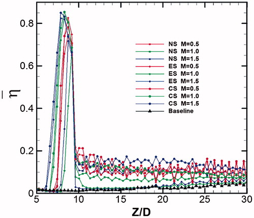
illustrates the laterally averaged adiabatic cooling effectiveness on the endwall. The region near the leading edge ((Z/D = 0) obtains a relatively low level of the cooling effectiveness due to the presence of the hot ring around the leading edge. Moreover, the results indicate that the introduction of the pressure side injection slot has a significant effect in the region 5≤Z/D ≤ 30. This can be explained by the fact that the cooling benefit of the pressure side injection slot is limited within the region along the pressure side as shown in . Consequently, the region along the pressure side was investigated in details to clarify the influence of the pressure side coolant injection.
Figure 7. Laterally-averaged cooling effectiveness on the endwall.
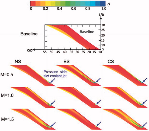
shows the endwall adiabatic cooling effectiveness on the pressure side region. The results indicate that the cooling effectiveness on the pressure side endwall surface is increased significantly by introducing the pressure side injection slot. The NS and CS achieve increasing cooling effectiveness with an increase of the blowing ratio. More importantly, the lateral expansion of the coolant jet is increased with the increase of the blowing ratio, resulting in an increase of the coolant coverage. Nevertheless, the ES obtains the largest coolant coverage at a small blowing ratio . The coolant coverage is significantly decreased at the blowing ratio, and increases from
to
. Overall, the CS achieves the largest coolant coverage at
for all investigated cases.
Figure 8. Adiabatic cooling effectiveness on the pressure side endwall surface.
presents the laterally averaged adiabatic cooling effectiveness on the pressure side endwall surface. The baseline case obtains the lowest level of cooling effectiveness on the pressure side endwall surface. The largest laterally averaged cooling effectiveness is observed within 7 ≤ Z/D ≤ 9 for all cases. This is because the pressure side slot outlet is located within this region (7 ≤ Z/D ≤ 9). Hence, the local cooling effectiveness is increased drastically. The CS obtains a relatively larger cooling effectiveness than the NS and the ES, especially at the downstream region of the pressure side injection slot (10 ≤ Z/D ≤ 30). lists the area-averaged cooling effectiveness on the pressure side endwall surface as shown in . The results indicate that the pressure side area-averaged cooling effectiveness is increased by introducing the pressure side injection slot. The ES achieves the largest cooling effectiveness at . However, the CS obtains the largest cooling effectiveness at the large blowing ratios (
and
).
Figure 9. Laterally-averaged adiabatic cooling effectiveness on the pressure side endwall surface.
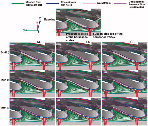
As shown in , the vortices near the vane pressure side have a tremendous influence on the endwall cooling effectiveness, resulting in hot regions on the endwall surface. shows the flow streamlines of the mainstream and the coolant near the endwall surface. The coolant from the upstream slot and the leading edge film holes is confined within the region between pressure side leg and suction side leg of the horseshoe vortex. Consequently, the region between the pressure side leg of the horseshoe vortex and vane pressure side is exposed to the hot gas and endures a high level of thermal load. For the ES, the coolant spreads widely at a small blowing ratio M = 0.5 and hence obtains a relatively large coolant coverage. In contrast, the coolant stays close to the pressure side surface for the NS and CS at M = 0.5. With the increase of the blowing ratio, the coolant spreads to a larger region for the NS and CS. Therefore, the coolant jet encounters the pressure side leg of the horseshoe vortex at the downstream region. The lateral vertical flow forces the coolant toward the suction side. As a result, the coolant coverage is expanded by the assistance of the pressure side vertical flow.
Figure 10. Flow structure near the endwall surface.
In order to clarify the influence of the pressure side coolant jet on the cooling performance and flow field near the pressure side endwall, the cooling effectiveness, the flow structure, and temperature on four different cross-sections near the vane pressure side are illustrated in . In this study, the non-dimensional temperature , is based on the temperatures of the mainstream and the coolant. The
-values zero and unity signify the minimum and maximum temperatures, respectively. The non-dimensional temperature θ is defined as:
(3) where
is the local temperature,
and
are the temperatures of the mainstream and coolant, respectively.
Figure 11. Cooling effectiveness, flow and thermal fields near the vane pressure side.
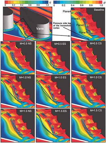
The results indicate that the coolant coverage near the vane pressure side is significantly increased by introducing the pressure side injection slot relative to the baseline case, especially at high blowing ratios. For the NS and CS, the expansion of the coolant can be enlarged at the downstream region. This can be explained by the fact that the pressure side vertical flow forces the coolant jet near the endwall surface toward the suction side. This lateral motion contributes to the enhancement of the expansion of the coolant jet, especially at the downstream region. Consequently, the coolant coverage is significantly increased at the downstream region for the NS and CS. Nevertheless, the ES shows a significant decrease of the coolant coverage near the pressure side when the blowing ratio increases from M = 0.5 to M = 1.0, and M = 1.5. This is because the coolant is lifted off the endwall surface for the ES at M = 1.0 and M = 1.5. As illustrated in , a vortex is generated near the pressure side, and it lifts the coolant off the endwall surface at the blowing ratios M = 1.0 and M = 1.5. Therefore, the coolant coverage on the pressure side endwall surface is significantly reduced in comparison with the NS and CS. Overall, the coolant jet from the CS spreads wider and achieves larger coolant coverage than the NS and the ES, especially at a high blowing ratio.
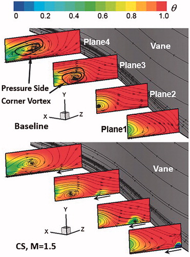
shows the streamlines and the distribution near the vane pressure side. The baseline case and the CS with M = 0.5 are selected to investigate the influence of the pressure side vortical flow on the lateral expansion of the coolant jet. The results indicate that the pressure side corner vortex and the pressure side leg of the horseshoe vortex prevent the coolant from the upstream slot and the leading edge film holes move it toward vane pressure side. This is because the flow directions of the coolant from the upstream slot and the leading edge film holes are opposite to the vortical flow near the vane pressure side. However, the coolant jet from the pressure side injection slot can be assisted by the vortical flow near the pressure side to increase the lateral expansion. As shown in , the vortical flow near the vane pressure side forces the coolant jet from the pressure side inejction slot toward the adjacent vane suction side. As a result, the lateral expansion is gradually increased along the downstream direction due to the enhancement of the pressure side vortical flow.
Figure 12. Flow structure and the temperature distribution near the vane pressure side.
3.3. Aerodynamic performance
This section aims to analyze the aerodynamic performance of the cases with the pressure side injection slot relative to the baseline case. The total pressure loss coefficient is selected as the evaluation for all investigated cases. The total pressure loss coefficient is defined as the ratio of the inlet-outlet total pressure difference and the mainstream inlet kinetic energy.
(4) where
, and
are the total pressure at the inlet plane and outlet plane, respectively.
is the mass flow rate averaged density of the fluid at the inlet plane.
is the mass flow rate averaged velocity at the inlet plane.
displays the distribution of the total pressure loss coefficient on the outlet plane a distance of 1.5 axial chords downstream of the trailing edge. There is no significant difference among the cases. shows the total pressure loss coefficient along the span-wise direction at the outlet plane. All cases share a similar variation along the span-wise direction. lists the area-averaged total pressure loss coefficient at the outlet plane. The biggest difference of total pressure loss coefficient is about 0.15% for the ES at M = 1.0 and M = 1.5. The CS obtains the relatively smallest total pressure loss in comparison with the NS and ES. Overall, the introduction of the pressure side injection slot has a very small influence on the vane cascade aerodynamic performance.
Figure 13. Total pressure loss coefficient on the outlet plane.
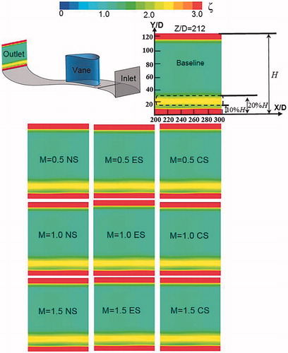
Figure 14. Total pressure loss coefficient along the span-wise direction at the outlet plane.
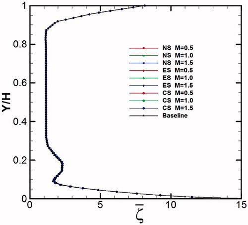
Table 4. Area-averaged cooling effectiveness long pressure side
Table 5. Area-averaged total pressure loss coefficient along the span wise direction at the outlet plane
4. Conclusions
In this study, the effects of a pressure side injection slot on the cooling performance of the endwall surface have been investigated. The results indicate that the introduction of the pressure side injection slot provides a great contribution to increase the cooling effectiveness of the pressure side endwall surface relative to the baseline case. Overall, the pressure side injection slot results in a very small aerodynamic loss in the vane cascade.
The ES achieves the largest cooling effectiveness near the pressure side at M = 0.5. As the blowing ratio increases from M = 0.5 to M = 1.0, the ES shows a drastic decrease of the coolant coverage due to the coolant being lifted off the endwall. In contrast, the NS and CS obtain a significant increase of the coolant coverage and cooling effectiveness with an increase of the blowing ratio. The CS achieves a larger coolant coverage and cooling effectiveness than the NS and ES at M = 1.0 and M = 1.5. This is because the coolant jet from the CS at a high blowing ratio encounters the pressure side vortical flow. Then the coolant jet will be driven by the pressure side vortical flow toward the suction side, resulting in the expansion of the coolant coverage at downstream region of the injection slot.
In addition, the results show that the introduction of the pressure side injection slot leads to a small increase of the total pressure loss in the vane cascade. The biggest total pressure loss coefficient is about 0.15% for the case with ES at M = 1.5. More importantly, the CS induces a smaller total pressure loss than the NS and ES at any blowing ratio.
| Nomenclature | ||
| = | diameter of film hole | |
| = | height of vane | |
| = | mass flow rate | |
| = | temperature | |
| = | adiabatic temperature | |
| = | coolant temperature | |
| = | mainstream temperature | |
| = | velocity | |
| = | lateral coordinate | |
| = | vertical coordinate | |
| = | dimensionless wall-normal height of first cell | |
| = | direction along the axial chord length | |
| Greek symbols | = | |
| = | coolant jet angle from the upstream slot film hole | |
| = | total pressure loss coefficient | |
| = | laterally-averaged total pressure loss coefficient | |
| = | area-averaged total pressure loss coefficient | |
| = | non-dimensional temperature | |
| = | adiabatic cooling effectiveness | |
| = | laterally averaged adiabatic cooling effectiveness | |
| = | area-averaged adiabatic cooling effectiveness | |
| Subscript | = | |
| = | adiabatic wall condition | |
| = | coolant conditions | |
| = | inlet condition | |
| = | outlet condition | |
| = | mainstream conditions | |
Acknowledgments
The authors gratefully acknowledge the support of China Scholarship Council (CSC), the National Natural Science Foundation of China [No. 51776151], the Swedish Research Council (VR) and the Swedish National Energy Agency (EM).
References
- S. Hada, and K. A. Thole, “Computational Study of a Midpassage Gap and Upstream Slot on Vane Endwall Film Cooling,” ASME Paper No. GT-2006–91067, 2006.
- J. C. Han, S. Dutta, and S. Ekkad, Gas Turbine Heat Transfer and Cooling Technology, 2nd ed. Boca Raton, FL, USA: Taylor & Francis Group, CRC Press, 2012.
- T. W. Simon, and J. D. Piggush, “Turbine endwall aerodynamics and heat transfer,” J. Propul. Power., vol. 22, no. 2, pp. 249–270, 2006. DOI: 10.2514/1.16344.
- S. Friedrichs, H. P. Hodson, and W. N. Dawes, “Distribution of film-cooling effectiveness on a turbine endwall measured using the ammonia and diazo technique,” J. Turbomach., vol. 118, no. 4, pp. 613–621, 1996. DOI: 10.1115/1.2840916.
- S. Friedrichs, H. P. Hodson, and W. N. Dawes, “Aerodynamic aspects of endwall film-cooling,” J. Turbomach., vol. 119, no. 4, pp. 786–793, 1997. DOI: 10.1115/1.2841189.
- R.S. Bunker, “A review of shaped hole turbine film-cooling technology,” J. Heat Transfer., vol. 127, no. 4, pp. 441–453, 2005. DOI: 10.1115/1.1860562.
- Z. Gao, D. Narzary, and J. C. Han, “Turbine blade platform film cooling with typical stator-rotor purge flow and discrete-hole film cooling,” J. Turbomach., vol. 131, no. 4, pp. 041004, 2009. DOI: 10.1115/1.3068327.
- X. Yang, Z. Liu, and Z. Feng, “Numerical evaluation of novel shaped holes for enhancing film cooling performance,” J. Heat Transfer., vol. 137, no. 7, p. 071701, 2015. DOI: 10.1115/1.4029817.
- J. Wang, P. Cui, and B. Sunden, “Effects of deposition height and width on film cooling,” Numer. Heat Transfer A., vol. 70, no. 6, pp. 673–687, 2016. DOI: 10.1080/10407782.2016.1193351.
- K. Du, L. Song, and J. Li, “Effects of the layout of film holes near the vane leading edge on the endwall cooling and phantom cooling of the vane suction side surface,” Numer. Heat Transfer A., vol. 71, no. 9, pp. 910–927, 2017. DOI: 10.1080/10407782.2017.1326788.
- K. D. Lee, and K. Y. Kim, “Film cooling performance of cylindrical holes embedded in a transverse trench,” Numer. Heat Transfer A., vol. 65, no. 2, pp. 127–143, 2014. DOI: 10.1080/10407782.2013.826106.
- M. F. Blair, “An experimental study of heat transfer and film cooling on large-scale turbine endwall,” J. Heat Transfer., vol. 96, no. 4, pp. 524–529, 1974. DOI: 10.1115/1.3450239.
- H. Pasinato, K. Squires, and R. P. Roy, “Measurements and modeling of the flow and heat transfer in a contoured vane endwall passage,” Int. J. Heat Mass Tranfer., vol. 47, no. 26, pp. 5685–5702, 2004. DOI: 10.1016/j.ijheatmasstransfer.2004.07.032.
- M. Nicklas, “Film-cooled turbine endwall in a transonic flow field: part II—heat transfer and film-cooling effectiveness,” J. Turbomach., vol. 123, no. 4, pp. 720–729, 2001. DOI: 10.1115/1.1397308.
- N. D. Cardwell, N. Sundaram, and K. A. Thole, “Effect of midpassage gap, endwall misalignment, and roughness on endwall film-cooling,” J. Turbomach., vol. 128, no. 1, pp. 62–70, 2006. DOI: 10.1115/1.2098791.
- N. D. Cardwell, N. Sundaram, and K. A. Thole, “The effects of varying the combustor-turbine gap,” J. Turbomach., vol. 129, no. 4, pp. 756–764, 2007. DOI: 10.1115/1.2720497.
- K. Du, and J. Li, “Numerical study on the effects of slot injection configuration and endwall alignment mode on the film cooling performance of vane endwall,” Int. J. Heat Mass Tran., vol. 98, pp. 768–777, 2016. DOI: 10.1016/j.ijheatmasstransfer.2016.02.014.
- D. G. Knost, and K. A. Thole, “Adiabatic effectiveness measurements of endwall film-cooling for a first stage vane,” J. Turbomach., vol. 127, no. 2, pp. 297–305, 2005. DOI: 10.1115/1.1811099.
- K. Du, L. Song, and J. Li, “Influence of the upstream slot geometry on the endwall cooling and phantom cooling of vane suction side surface,” Appl. Therm. Eng., vol. 121, pp. 688–700, 2017. DOI: 10.1016/j.applthermaleng.2017.04.143.
- E. Kianpour, N A C. Sidik, and I. Golshokouh, “Measurement of film effectiveness for cylindrical and row trenched cooling holes at different blowing ratios,” Numer. Heat Transfer A., vol. 66, no. 10, pp. 1154–1171, 2014. DOI: 10.1080/10407782.2014.901042.
- K. Du, Z. Li, and J. Li, “Effects of the leading edge injection slot on the film cooling and heat transfer performance of the vane endwall,” Int. J. Heat Mass Tran., vol. 102, pp. 1308–1320, 2016. DOI: 10.1016/j.ijheatmasstransfer.2016.07.033.
- N. H. K. Chowdhury, C. C. Shiau, and J. C. Han, “Turbine vane endwall film cooling with slashface leakage and discrete hole configuration,” J. Turbomach., vol. 139, no. 6, p. 061003, 2017. DOI: 10.1115/1.4035162.
- K. Du, L. Song, and J. Li, “Effects of the mainstream turbulence intensity and slot injection angle on the endwall cooling and phantom cooling of the vane suction side surface,” Int. J. Heat Mass Tran., vol. 112, pp. 427–440, 2017. DOI: 10.1016/j.ijheatmasstransfer.2017.05.010.
- K. Takeishi, Y. Oda, and S. Kondo, “Film Cooling with Swirling Coolant Flow on a Flat Plate and the Endwall of High-Loaded First Nozzle,” ASME Paper No. GT2014–25798, 2014.
- K. Takeishi, M. Komiyama, and Y. Oda, “Aerothermal investigations on mixing flow field of film cooling with swirling coolant flow,” J. Turbomach., vol. 136, no. 5, p. 051001, 2014. DOI: 10.1115/1.4023909.