
Abstract
Heat transfer enhancement is of great importance for energy efficiency improvement. The utilization of spirally corrugated tubes is one of the efficient ways to strengthen heat transfer. In this article, based on a validated numerical model, the effects of geometric parameters of a six-start spirally corrugated tube, including the pitch p and the corrugation depth e, on the shell side heat transfer and flow resistance performance are numerically investigated, in high Reynolds number conditions ranging from 10,000 to 60,000. The shell side secondary flow velocity distribution, longitudinal vortex distribution, and temperature distribution of a six-start spirally corrugated tube are presented, respectively. In addition, the heat transfer and flow resistance characteristics are evaluated by comparing the Nusselt number and the flow resistance coefficient with these of smooth tubes. Results show that the utilization of six-start spirally corrugated tubes can enhance the heat transfer performance at the expense of an increase of the flow resistance. However, with the same geometric parameters, the Nusselt number increases and the flow resistance coefficient decreases as Reynolds number increases. With the pitch increasing, the Nusselt number and the flow resistance coefficient decrease at a fixed Reynolds number. In contrast, as the corrugation depth increasing, the Nusselt number changes irregularly, and the flow resistance coefficient increases. Finally, correlations for the shell side Nusselt number and flow resistance coefficient of the six-start spirally corrugated tube are established. This work is of significance for engineers and scientists focusing on the heat transfer and the flow resistance characteristics of spirally corrugated tubes and their applications.
1. Introduction
Nowadays, the increasing shortage of energy is a worldwide problem. Heat transfer enhancement is one of the methods to improve the energy efficiency and save energy. There are a lot of approaches to enhance heat transfer, and an appropriate way is to apply intensified heat exchanging tubes. Many scholars have contributed a lot in this specific field.
Pakhomov and Terekhov [Citation1] proposed a mathematical model to analyze the swirling turbulent gas-droplet flow in a sudden pipe expansion and found the heat transfer was increased by the flow swirl. For instance, Tian et al. [Citation2] studied the flow and heat transfer characteristics of a three-dimensional staggered circular-pin-finned tube numerically. Considering six geometric parameters and pin-fin arrangement in the flow direction, the results showed that the pin-fin diameter, pin-fin length, and pin-fin number around the tube had favorable effects on improving the thermo-hydraulic performance, while the transverse tube pitch and the fin axial pitch had detrimental effects, whereas the longitudinal tube pitch and the fin arrangement in flow direction had marginal effects. Petracci et al. [Citation3] investigated the average heat transfer on a finned cylinder cooled by a rectangular jet and optimized the fins to maximize the average heat transfer on the finned cylinder. Ravi et al. [Citation4] studied the heat transfer behavior of a phase change material fluid at laminar flow conditions in circular tubes and internally longitudinal finned tubes, pointing out that the Nusselt number was strongly depending on the Stefan number, fin thermal conductivity value, and height of the fins. Kim et al. [Citation5] conducted a numerical analysis which produced a series of full flow visualizations to clarify the governing mechanisms in fin tube flow, to study the turbulent flow and heat transfer mechanisms in internally finned tubes, and found that the governing physics of tall fin and microfin tubes are different. Shome [Citation6] numerically investigated the developing mixed convection flow in internally finned tubes with variable viscosity. They found that coring leads to poor heat transfer performance of tubes with large numbers of fins or with tall fins and that large enhancement in the heat transfer can be obtained in the entrance region. In addition, it was found that viscosity had a pronounced effect on the friction factor and Nusselt number predictions. Dandotiya and Banker [Citation7] carried out two new fin configurations to incorporate with a phase change material based heat exchanger, and the heat transfer enhancement was investigated numerically. It was found that the placement of fins is of significant effect on the heat transfer.
Li et al. [Citation8] developed a novel tube insert, named centrally hollow narrow twisted tape and analyzed the effect of the hollow width and clearance on heat transfer and flow resistance characteristics. It was found that the overall performance increased for laminar flow. Liu et al. [Citation9] studied the heat transfer and friction factor of a circular tube with central slant rods numerically, and the results showed that this novel insert can fully disturb the core flow inside circular tubes. They also investigated the effects of geometric parameters of inserts on heat transfer and friction factor characteristics, and the optimum geometric parameters were obtained. Zhang et al. [Citation10] studied a tube with multiple regularly spaced twisted tapes and found similar conclusions. Cao et al. [Citation11] proposed a novel enhanced heat transfer tube with segmented mesh-conical frustums. In the research, laminar thermal-hydraulic performance and effects of the insert geometric parameters were numerically simulated. They found that the novel inserts enhanced heat transfer with a limited pressure drop. In addition, Nusselt number and friction factor correlations were proposed. Shabanian et al. [Citation12] developed a feed-forward artificial neural network (ANN) to estimate the Nusselt number, friction factor, and thermal performance in a tube equipped with a perforated twisted tape and several superior empirical equations were proposed. Beigzadeh et al. [Citation13] applied the hybrid model, including back propagation network and genetic algorithm, to predict the thermal and flow characteristics in a rectangular channel fitted with multiple twisted tape vortex generators. They found that the performance of the developed neural networks was superior in comparison with the empirical correlations.
Ebrahimi and Roohi [Citation14] investigated flow patterns and heat transfer inside mini-twisted oval tubes numerically, and the relationships between the configurations of the tubes and the overall performance of mini-twisted oval tubes were summarized. Tan et al. [Citation15–17] carried out investigations of a twisted oval tube heat exchanger. They studied the heat transfer and pressure drop performance of a twisted oval tube heat exchanger on both the tube side and shell side experimentally. By conducting a comparison with a rod baffle heat exchanger, they found the twisted oval tube heat exchanger had a more superior overall performance.
Spirally corrugated tubes are novel intensified heat exchanger tubes, which have been widely used in heat exchangers. Many scholars have paid attention to the performance of spirally corrugated tubes.
Promthaisong et al. [Citation18] carried out a 3D numerical study on the effects of spirally corrugated tubes on the turbulent convection and obtained the maximum thermal enhancement at the specific combination of geometric parameters and operating conditions. Lu et al. [Citation19] studied the transition and turbulent convective heat transfer of molten salt in a spirally corrugated tube experimentally. The results showed that the Nusselt number of the molten salt flow inside was higher than that of a smooth tube, and a corrugation depth increment can remarkably enhance the heat transfer. They also modified correlations for molten salt flow in the spirally corrugated tube. Zachár [Citation20] studied the improvement of the heat transfer rate in a coiled-tube heat exchanger with spirally corrugated walls numerically. Darzi et al. [Citation21–23] studied the effect of a nanofluid on turbulent heat transfer and pressure drop inside spirally corrugated tubes experimentally and numerically. They found that with the nanofluid in the tube, a deep corrugation and small pitch can augment the heat transfer with negligible pressure drop penalty. In addition, the heat transfer and friction factor also increased when the nanofluid concentration increased. Zimparov [Citation24,Citation25] proposed a simple mathematical model to predict the heat transfer coefficients and the friction factors for the case of a fully developed turbulent flow in a single start spirally corrugated tube combined with a twisted tape insert.
Investigations of a multi-start spirally corrugated tube have been carried out by several researchers. Liu et al. [Citation26] conducted a numerical study on the shell side heat transfer and flow characteristics of rod-baffle heat exchangers with spirally corrugated tubes. In the investigation, they proposed four models: one-start, two-start, three-start, and four-start spirally corrugated tubes in RBHXsSCT (rod-baffle heat exchangers with spirally corrugated tubes), and the results showed that when Reynolds number ranged from 6,000 to 18,000, compared with RBHX (rod-baffle heat exchangers with plain tubes), the heat transfer quantities were higher and the pressure drop was lower. Kareem et al. [Citation27] studied the heat transfer enhancement in a three-start spirally corrugated tube experimentally and numerically, and found that at low Reynolds number; the three-start spirally corrugated tube can improve the heat transfer significantly with a modest increase in the friction factor. Chen et al. [Citation28] conducted an experiment, focusing on the non-symmetric nature of the corrugation angles along the longitudinal direction of four-start spirally corrugated tubes, and found that altering the internal non-symmetric wavy shapes of the tubes enabled to manipulation of the heat transfer and friction characteristics. Pitak et al. [Citation29] numerically investigated the turbulent airflow in a five-start spirally corrugated tube with different pitches, and found that the five-start spirally corrugated tube can enhance the heat transfer rate and augment the friction factor.
In our previous work [Citation30–32], the effects of pitch and corrugation depth on heat transfer performance and flow resistance characteristics inside a six-start spirally corrugated tubes have been studied numerically by calculating the Nusselt number and flow resistance coefficient. However, for the heat transfer and flow resistance on the shell side research, investigations are missing. In this article, the flow domain on the shell side of a six-start spirally corrugated tube is proposed. Based on a validated numerical model, the secondary flow velocity distribution, longitudinal vortex distribution, and temperature distribution of the fluid are investigated to reveal the heat transfer performance and flow resistance characteristics. The study should be of interest for researchers and engineers dealing with the heat transfer and the flow resistance characteristics of spirally corrugated tubes.
2. Numerical model
2.1. Geometrical model
The spirally corrugated tube considered in this study is a six-start spirally corrugated tube, as shown in , which can be made by rolling out a smooth copper tube. The main structural parameters are the pitch p, the corrugation depth e, and outside diameter Do, as shown in .
Figure 1. Geometries of a six-start spirally corrugated tube. (a) Geometric model of tube and (b) Geometric parameters of tube.
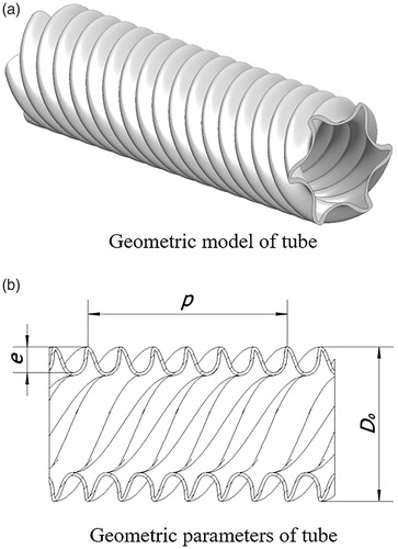
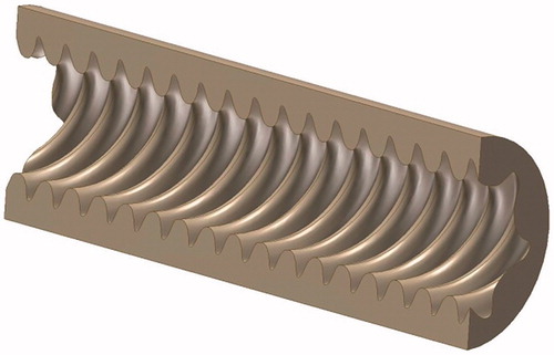
Here, a shell side flow channel of a six-start corrugated tube is established, as shown in . Considering the shell side actual size of coaxial heat exchangers, where spirally corrugated tubes are widely used, the geometric parameters of this model are as follows: the length is 600 mm, the inner wall of the model is the outer surface of a six-start spirally corrugated tube with an outside diameter of 27 mm, and the outer wall of the model is a cylindrical surface with a diameter of 35 mm.
Figure 2. Shell side flow channel model of a six-start spirally corrugated tube.
2.2. Mesh and boundary condition
Because the structure of the numerical model is twisted, and the fluid adjacent to the wall of the six-start spirally corrugated tube is complex, a tetrahedral mesh is used. Before carrying out the whole simulation grid independence verification is conducted and 1.2 mm is chosen as the simulation mesh size.
In this article, the shell side of a six-start spirally corrugated tube is numerically simulated by the commercial software ANSYS FLUENT (Canonsburg, PA). Water is adapted to be the heat transfer medium, of which the physical parameters are as follows: density is 998.2 kg/m3, specific heat is 4,182 J/kg.K, thermal conductivity is 0.6 W/m.K, and viscosity is 1.006 mPa.s. The inlet boundary condition is set as a velocity inlet and the temperature is 300 K. The outlet boundary condition is set as a pressure outlet and the pressure is 0 Pa. No-slip wall condition is applied on all walls, the temperature of the cylindrical wall is 300 K, and the temperature of the spirally corrugated tube wall is 363 K. Copper is selected as the material for both walls.
The model assumes single-phase flow and heat transfer. Reynolds number ranges from 10,000 to 60,000. As the shell side heat transfer of the six-start spirally corrugated tube is complicated, the realizable k–ε turbulence model combined with the wall function method is used in the simulations. The calculation procedures are assumed steady 3D flow, and the pressure implicit solver, algorithm SIMPLE is used to couple pressure and velocity. Momentum, turbulent kinetic energy, turbulent dissipation rate, and energy equations are all treated by a second-order upwind scheme.
2.3. Reliability verification
In this section, a smooth tube with a diameter of 8 mm and a length of 600 mm is considered. The internal fluid flow of the smooth tube is numerically simulated for the same conditions mentioned above. Empirical formulas [Citation33] are used to verify the reliability of the numerical method. The Nusselt number Nu and the flow resistance coefficient f, obtained from the numerical simulation, are compared with the values derived from the empirical formulas, respectively. The simulated Nu can be derived from EquationEq. (1)(1) :
(1)
where h is the heat transfer coefficient, d is the diameter of the smooth tube, and λ is the thermal conductivity of the heat transfer medium. The simulated flow resistant coefficient can be calculated from EquationEq. (2)
(2) :
(2)
where d is the diameter of the smooth tube, Δp is the inlet to outlet pressure difference, u is the mean inlet velocity, and l is the length of the smooth tube. The empirical value of Nusselt number Nu is derived from Sieder–Tate formula, expressed as EquationEq. (3)
(3) :
(3)
where μ is the viscosity and μw is the viscosity at the tube wall temperature. The Sieder–Tate formula is suitable for a smooth tube and can be used for the conditions: Re≥ 104, Pr= 0.7 ∼ 16,700, l/d≥ 60. The empirical value of the flow resistance coefficient is derived from Blasius formula:
(4)
Blasius formula works for a smooth tube under the condition of 2,100<Re< 105.
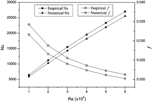
The simulated and empirical values of Nu and f are shown in . According to , the maximum relative error between the numerical and empirical values of Nu is 4.53%, and the maximum relative error of f is 4.86%. Both of them are less than 5%. Therefore, the numerical simulation method is regarded to be reliable.
Figure 3. Results of validity verification.
3. Results and discussion
The pitch p and the corrugation depth e are two key geometric parameters of six-start spirally corrugated tubes. In this part, the effects of these two parameters on the shell side heat transfer and flow performance of a six-start spirally corrugated tube are analyzed in detail.
3.1. Analysis of effects of pitch
In this section, effects of pitch on the shell side heat transfer performance and flow resistance characteristics of six-start spirally corrugated tubes are investigated. In order to eliminate the effect of other geometric parameters, the control variable method is adopted. The geometric parameters of six-start spirally corrugated tubes with different pitches are listed in .
Table 1. Geometric parameters of six-start spirally corrugated tubes with different pitches.
3.1.1. Shell side heat transfer characteristics
The Nusselt numbers Nu of the fluid on shell side of six-start spirally corrugated tubes under different Reynolds number ranging from 10,000 to 60,000 are shown in . It shows that the Nusselt number decreases with an increase of the pitch at a fixed Reynolds number, which indicates that for the shell side of a six-start spirally corrugated tube, a reduction of the pitch can improve the heat transfer performance within suitable ranges.
Table 2. Shell side Nusselt number of six-start spirally corrugated tubes with different pitches.
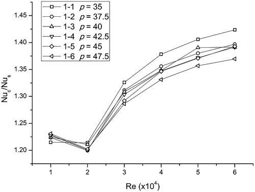
To further investigate the shell side heat transfer performance of the six-start spirally corrugated tube, a comparison of Nusselt numbers between the six-start spirally corrugated tube and the smooth tube with the same equivalent diameter is conducted. shows that the six-start spirally corrugated tube has an advantage on the shell side heat transfer performance. The value of Nuc/Nus, which represents the ratio of Nusselt numbers between the six-start spirally corrugated tube and the smooth tube, ranges from 1.19 to 1.42. When Re = 10,000, the effect of the six-start spirally corrugated tube on the shell side heat transfer increases with an increase of the pitch. However, when Re ≥ 20,000, the effect decreases with the increase of the pitch. In addition, for the six-start spirally corrugated tube with a constant pitch, the reinforcement of heat transfer is reduced when Re < 20,000, while it increases when Re ≥ 20,000, but the increasing trend becomes more and more gentle with increasing Re.
Figure 4. Ratio of Nuc/Nus between six-start spirally corrugated tubes and smooth tubes.
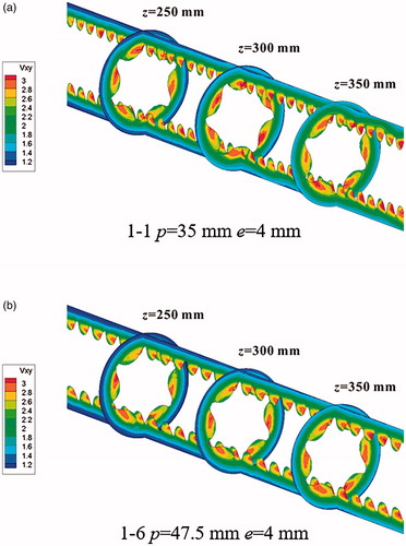
The magnitude of the secondary flow velocity is affected by the corrugations of the six-start spirally corrugated tube. shows the secondary flow velocity contours of the six-start spirally corrugated tubes with pitches of 35 and 47.5 mm, at a Reynolds number Re = 40,000. In , the cross sections of z= 250, 300, and 350 mm are extracted (the inlet is located at z= 0 and the outlet is located at z = 600 mm). It can be concluded that the secondary flow velocity, represented by vxy, decreases with an increase of the pitch. In addition, the secondary flow velocity is low at the cylindrical wall while high near the corrugations. Another result is that the secondary flow velocity at the cylindrical wall of the six-start spirally corrugated tube with a pith of 35 mm is larger than that of the six-start spirally corrugated tube with a pith of 47.5 mm. In other words, a smaller pitch has a wider influence on the disturbance of the secondary flow.
Figure 5. Secondary velocities of six-start spirally corrugated tubes with different pitches.
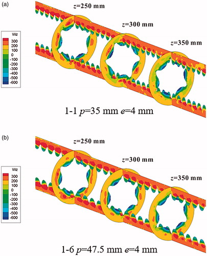
The shell side vorticities in the axial direction of the six-start spirally corrugated tube, calculated by EquationEq. (5)(5) [Citation30] (where v and u represent the velocity components in the x and y directions), are examined in . It shows the longitudinal shell side vorticities of the six-start spirally corrugated tubes with pitches p= 35 and 47.5 mm. The operating condition of the flow is Re= 40,000. It is found that the longitudinal vorticity decreases with increasing pitch, although the difference is not large. The indication is that, for the shell side of six-start spirally corrugated tubes, a smaller pitch results in a better heat transfer performance.
(5)
Figure 6. Shell side vorticities of six-start spirally corrugated tubes with different pitches.
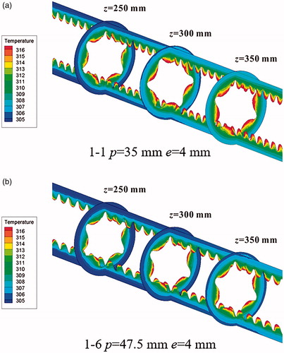
The heat transfer performance is affected not only by the velocity distribution but also by the temperature distribution. A larger temperature difference means a greater heat transfer potential. Thus, it is of significance to investigate the shell side temperature distribution of the six-start spirally corrugated tube. shows the shell side temperature distributions of the six-start spirally corrugated tubes with pitches of 35 and 47.5 mm at Re= 40,000. From , it is evident that the temperature contours are dense around the corrugations, especially in the protruding part of the corrugations. This indicates that the spiral corrugations can produce a larger temperature difference. Besides, as the pitch increases, the temperature contours become sparser, especially adjacent to the cylindrical wall, which implies that the heat transfer decreases as the pitch increases. Therefore, a smaller pitch is more suitable to enhance the shell side heat transfer performance.
Figure 7. Shell side temperature distribution of six-start spirally corrugated tubes with different pitches.
3.1.2. Shell side pressure drop characteristics
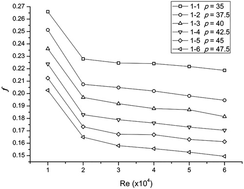
In this section, the effect of pitch on the shell side flow resistance characteristics of the six-start spirally corrugated tube is investigated. The flow resistance coefficient f at different Reynolds number is shown in . It is obvious that the flow resistance coefficient decreases as the pitch increases at a fixed Reynolds number. On the other hand, if the pitch is kept constant, the flow resistance coefficient decreases when the Reynolds number increases.
Figure 8. The shell side flow resistance coefficients of six-start spirally corrugated tubes with different pitches.
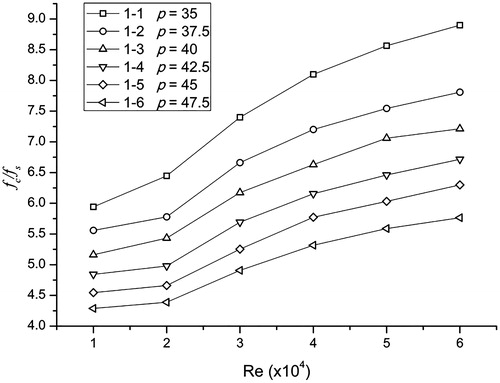
Compared with a smooth tube, the six-start spirally corrugated tube enlarges the distance the fluid flows through, due to the existence of corrugations. This is why the flow resistance increases. In order to show the increase of the shell side flow resistance of the six-start spirally corrugated tube more directly, the ratio fc/fs is depicted in , where fc and fs represent the flow resistance coefficient of the six-start spirally corrugated tube and smooth tube, respectively. It is evident that for the shell side flow resistance coefficient, the six-start spirally corrugated tube provides a much higher value than the smooth tube, and the former is 4.3–8.9 times as much as the latter.
Figure 9. Ratio of the shell side flow resistance coefficient (fc/fs) between six-start spirally corrugated tubes and smooth tubes.
As is mentioned above, a smaller pitch is favorable to enhance the shell side heat transfer performance of the six-start spirally corrugated tube. However, the increase of the flow resistance must also be considered.
3.2. Analysis of effects of corrugation depth
In this section, the effects of the corrugation depth on the shell side heat transfer performance are investigated. Similar to the above part, the control variable method is also adopted here. The geometric parameters of the six-start spirally corrugated tubes with different corrugation depths are listed in .
Table 3. Geometric parameters of six-start spirally corrugated tubes with different corrugation depths.
3.2.1. Shell side heat transfer characteristics
The shell side Nusselt numbers Nu of the six-start spirally corrugated tubes with different corrugation depths are depicted in . It is found from that there is no obvious regularity in the effect of the corrugation depth on the shell side heat transfer performance.
Table 4. Shell side Nusselt number of six-start spirally corrugated tubes with different corrugation depths.
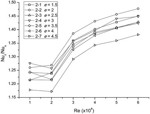
In terms of shell side heat transfer enhancement, which is caused by the six-start spirally corrugated tube, the values of Nuc/Nus are shown in . From , it is concluded that the utilization of the six-start spirally corrugated tube with different corrugation depths can enhance the shell side heat transfer obviously, and the multiplier factor ranges from 1.17 to 1.48. However, the regularity of the effect of corrugation depth on the shell side heat transfer enhancement is not regular.
Figure 10. Ratio of Nuc/Nus between six-start spirally corrugated tubes and smooth tubes.
3.2.2. Shell side pressure drop characteristics
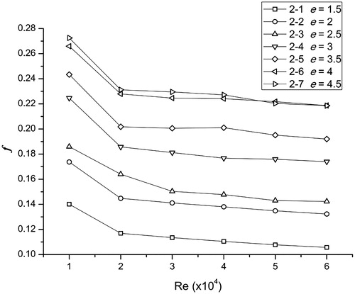
In this section, the effect of corrugation depth on the shell side flow resistance characteristics of the six-start spirally corrugated tube is investigated, and results are shown in . It is found that when the corrugation depth is kept constant, the flow- resistant coefficient decreases with the increase of Reynolds number. If the Reynolds number is kept constant, the flow resistance coefficient increases as the corrugation depth increasing, which indicates that a deeper corrugation results in a higher-pressure drop.
Figure 11. The shell side flow resistance coefficient of the six-start spirally corrugated tubes with different corrugation depths.
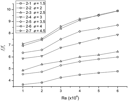
Furthermore, the value of fc/fs changes with Reynolds number, which indicates that the increase of the shell side flow resistance coefficient appears for the six-start spirally corrugated tube (see ). The value of fc/fs ranges from 3.67 to 9.90. If the Reynolds number is kept constant, fc/fs increases with an increase of the corrugation depth. In other words, a deeper corrugation will increase the flow resistance drastically. Besides, as seen from , the lines of e= 4 and 4.5 are highly coinciding, so the increase of the flow resistance caused by an increase of the corrugation depth is not as drastic when the corrugation is deeper than 4 mm.
Figure 12. Ratio of the shell side flow resistance coefficient (fc/fs) between six-start spirally corrugated tubes and the smooth tubes (a) Model of Nusselt number (b) Model of flow resistance coefficient.
3.3. Correlation
In the above analyzes, the effects of pitch and corrugation depth of the six-start spirally corrugated tube on the shell side heat transfer performance, represented by Nusselt number Nu, and on the shell side flow resistance characteristics, represented by the flow resistance coefficient f were investigated. Based on the research data, correlations for the shell side Nusselt number and the flow resistance coefficient of the six-start spirally corrugated tube can be obtained.
It is found that the pitch p, corrugation depth e, equivalent diameter d, and Reynolds number Re, all have influence on Nusselt number Nu and the flow resistance coefficient f. The dimensionless parameters, including p/d, e/d, and Re, are adopted to describe correlations [Citation23,Citation24]. The correlations for Nusselt number Nu and the flow resistance coefficient f can be expressed as power functions:
(6)
(7)
where, C1 and C2 are constants of the correlations, respectively.
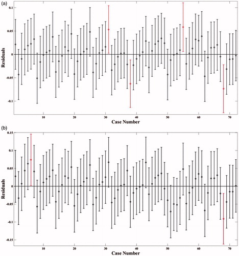
The software MATLAB (Mathworks, Natick, MA) is used for this analysis. The specific method has been adapted from reference [Citation23]. The residual plots of the two regressions are shown in . The two correlations are established and can be obtained as follows:
(8)
(9)
Figure 13. Residual plots of regression models (a) Model of Nusselt number and (b) Model of flow resistance coeffitient.
These correlations are applicable for the conditions that 3.06 < p/d < 4.17, 0.16 < e/d < 0.39, 10,000 ≤ Re ≤ 60,000, and 60 < L/d.
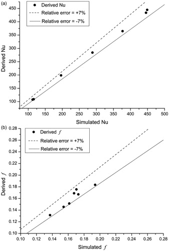
To find out the suitable conditions of the criterion correlations, several cases have been numerically simulated to obtain the accuracies. The relative errors between the values derived from the correlations and the values obtained from the numerical simulations are depicted in . It can be seen that for Nusselt number Nu and flow resistance coefficient f, the relative errors are both within the range of ±7%. Thus, it can be concluded that the correlations are reasonably accurate.
Figure 14. Relative errors between derived and simulaed. (a) Relative errors of Nu and (b) Relative errors of f.
4. Conclusions
In this article, the effects of two geometric parameters of a six-start spirally corrugated tube, i.e., pitch p and corrugation depth e, on the shell side heat transfer performance and flow resistance characteristics were numerically investigated. The results of the investigation are as follows.
First, the utilization of a six-start spirally corrugated tube can enhance the shell side heat transfer and increase the shell side flow resistance. The shell side Nusselt number is 1.17–1.48 times as much as that of a smooth tube. On the other hand, the shell side resistance coefficient is 3.67–9.90 times as much as that of a smooth tube. Second, for the same geometric conditions, as the Reynolds number increases, the Nusselt number increases while the flow resistance coefficient decreases gradually. Third, as the pitch increases, the Nusselt number and the flow resistance coefficient decrease at a fixed Reynolds number and as the corrugation depth increases, the regularity of the Nusselt number behavior is uncertain. Finally, correlations to calculate the shell side Nusselt number and the flow resistance coefficient of the six-start spirally corrugated tube are established and the relative errors between the derived value and simulated value are in the range of ±7%.
This work should be of interest for engineers and scientists dealing with the heat transfer performance and the flow resistance characteristics of spirally corrugated tubes. It may also stimulate further research on heat transfer performance and flow resistance characteristics of multi-start spirally corrugated tubes.
Additional information
Funding
References
- M. A. Pakhomov and V. I. Terekhov, “Numerical modeling of turbulent flow structure and heat transfer in a droplet-laden swirling flow in a pipe with a sudden expansion,” Numer. Heat Transfer A., vol. 71, no. 7, pp. 721–736, 2017. DOI: 10.1080/10407782.2017.1308740.
- E. Tian, Y. L. He, and W. Q. Tao, “Numerical simulation of finned tube bank across a staggered circular-pin-finned tube bundle,” Numer. Heat Transfer A., vol. 68, no. 7, pp. 737–760, 2015. DOI: 10.1080/10407782.2015.1012855.
- I. Petracci, M. Luca, and G. Fabio, “Numerical simulation of the optimal spacing for a radial finned tube cooled by a rectangular jet. I – average thermal results,” Int. J. Therm. Sci., vol. 104, pp. 54–67, 2016. DOI: 10.1016/j.ijthermalsci.2016.01.001.
- G. Ravi, L. J. Alvarado, C. Marsh, and D. A. Kessler, “Laminar flow forced convection heat transfer behavior of a phase change material fluid in finned tubes,” Numer. Heat Transfer A., vol. 55, no. 8, pp. 721–738, 2009. DOI: 10.1080/10407780902864672.
- J. H. Kim, K. E. Jansen, and M. K. Jensen, “Analysis of heat transfer characteristics in internally finned tubes,” Numer. Heat Transfer A., vol. 46, no. 1, pp. 1–21, 2004. DOI: 10.1080/10407780490454296.
- B. Shome, “Mixed convection laminar flow and heat transfer of liquids in horizontal internally finned tubes,” Numer. Heat Transfer A., vol. 33, no. 1, pp. 65–83, 1998. DOI: 10.1080/10407789808913928.
- D. Dandotiya and N. D. Banker, “Numerical investigation of heat transfer enhancement in a multitube thermal energy storage heat exchanger using fins,” Numer. Heat Transfer A., vol. 72, no. 5, pp. 389–400, 2017. DOI: 10.1080/10407782.2017.1376976.
- P. Li, Z. Liu, W. Liu, and G. Chen, “Numerical study on heat transfer enhancement characteristics of tube inserted with centrally hollow narrow twisted tapes,” Int. J. Heat Mass Transfer., vol. 88, pp. 481–491, 2015. DOI: 10.1016/j.ijheatmasstransfer.2015.04.103.
- P. Liu, N. Zheng, and F. Shan, “Numerical study on characteristics of heat transfer and friction factor in a circular tube with central slant rods,” Int. J. Heat Mass Transfer., vol. 99, pp. 268–282, 2016. DOI: 10.1016/j.ijheatmasstransfer.2016.03.059.
- X. Zhang, Z. Liu, and W. Liu, “Numerical studies on heat transfer and flow characteristics for laminar flow in a tube with multiple regularly spaced twisted tapes,” Int. J. Therm. Sci., vol. 58, no. 2, pp. 157–167, 2012. DOI: 10.1016/j.ijthermalsci.2012.02.025.
- Z. Cao, Z. Wu, H. Luan, and B. Sunden, “Numerical study on heat transfer enhancement for laminar flow in a tube with mesh conical frustum inserts,” Numer. Heat Transfer A., vol. 72, no. 1, pp. 21–39, 2017. DOI: 10.1080/10407782.2017.1353386.
- S. R. Shabanian, I. Shiva, and T. Hatami, “Application of intelligent methods for the prediction and optimization of thermal characteristics in a tube equipped with perforated twisted tape,” Numer. Heat Transfer A., vol. 70, no. 1, pp. 30–47, 2016. DOI: 10.1080/10407782.2016.1139982.
- R. Beigzadeh, M. Rahimi, M. Parvizi, and S. Eiamsa, “Application of ann and Ga for the prediction and optimization of thermal and flow characteristics in a rectangular channel fitted with twisted tape vortex generators,” Numer. Heat Transfer A., vol. 65, no. 2, pp. 186–199, 2014. DOI: 10.1080/10407782.2013.826010.
- A. Ebrahimi and E. Roohi, “Numerical study of flow patterns and heat transfer in mini twisted oval tubes,” Int. J. Mod. Phys. C., vol. 26, no. 12, 1550140 [pp. 1–18], 2015. DOI: 10.1142/S0129183115501405.
- X. H. Tan, D. S. Zhu, G. Y. Zhou, and L. D. Zeng, “Heat transfer and pressure drop performance of twisted oval tube heat exchanger,” Appl. Therm. Eng., vol. 50, no. 1, pp. 374–383, 2013. DOI: 10.1016/j.applthermaleng.2012.06.037.
- X. H. Tan, D. S. Zhu, G. Y. Zhou, and L. D. Zeng, “Experimental and numerical study of convective heat transfer and fluid flow in twisted oval tubes,” Int. J. Heat Mass Transf., vol. 55, no. 17–18, pp. 4701–4710, 2012. DOI: 10.1016/j.ijheatmasstransfer.2012.04.030.
- X. H. Tan, D. S. Zhu, G. Y. Zhou, and L. Yang, “3D numerical simulation on the shell side heat transfer and pressure drop performances of twisted oval tube heat exchanger,” Int. J. Heat Mass Transf., vol. 65, pp. 244–253, 2013. DOI: 10.1016/j.ijheatmasstransfer.2013.06.011.
- P. Promthaisong, W. Jedsadaratanachai, and S. Eiamsa-ard, “3D numerical study on the flow topology and heat transfer characteristics of turbulent forced convection in a spirally corrugated tube,” Numer. Heat Transfer A., vol. 69, no. 6, pp. 607–629, 2016. DOI: 10.1080/10407782.2015.1069670.
- J. Lu, X. Sheng, J. Ding, and J. Yang, “Transition and turbulent convective heat transfer of molten salt in spirally grooved tube,” Exp. Therm. Fluid Sci., vol. 47, pp. 180–185, 2013. DOI: 10.1016/j.expthermflusci.2013.01.014.
- A. Zachár, “Analysis of coiled-tube heat exchangers to improve heat transfer rate with spirally corrugated wall,” Int. J. Heat Mass Transfer., vol. 53, no. 19, pp. 3928–3939, 2010. DOI: 10.1016/j.ijheatmasstransfer.2010.05.011.
- A. A. R. Darzi, M. Farhadi, and K. Sedighi, “Experimental investigation of turbulent heat transfer and flow characteristics of SiO2/water nano-fluid within helically corrugated tubes,” Int. Commun. Heat Mass Transfer., vol. 39, no. 9, pp. 1425–1434, 2012. DOI: 10.1016/j.icheatmasstransfer.2012.07.027.
- A. A. R. Darzi, M. Farhadi, and K. Sedighi, “Experimental investigation of convective heat transfer and friction factor of Al2O3/water nano-fluid in helically corrugated tube,” Exp. Therm. Fluid Sci., vol. 57, pp. 188–199, 2014. DOI: 10.1016/j.expthermflusci.2014.04.024.
- A. A. R. Darzi, M. Farhadi, and K. Sedighi, “Turbulent heat transfer of Al2O3–water nanofluid inside helically corrugated tubes: numerical study, Int. Commun. Heat Mass Transfer., vol. 41, pp. 68–75, 2013. DOI: 10.1016/j.icheatmasstransfer.2012.11.006.
- V. Zimparov, “Prediction of friction factors and heat transfer coefficients for turbulent flow in corrugated tubes combined with twisted tape inserts. Part 1: friction factors,” Int. J. Heat Mass Transfer., vol. 47, no. 3, pp. 589–599, 2004. DOI: 10.1016/j.ijheatmasstransfer.2003.08.004.
- V. Zimparov, “Prediction of friction factors and heat transfer coefficients for turbulent flow in corrugated tubes combined with twisted Tape Inserts. Part 2: Heat Transfer Coefficients,” Int. J. Heat Mass Transfer., vol. 47, no. 2, pp. 385–393, 2004. DOI: 10.1016/j.ijheatmasstransfer.2003.08.004.
- J. J. Liu, Z. C. Liu, and W. Liu, “3D numerical study on shell side heat transfer and flow characteristics of rod-baffle heat exchangers with spirally corrugated tubes,” Int. J. Therm. Sci., vol. 89, pp. 34–42, 2015. DOI: 10.1016/j.ijthermalsci.2014.10.011.
- Z. S. Kareem, S. Abdullah, and T. M. Lazim, “Heat transfer enhancement in three-start spirally corrugated tube: experimental and numerical study,” Chem. Eng. Sci., vol. 134, pp. 746–757, 2015. DOI: 10.1016/j.ces.2015.06.009.
- X. D. Chen, X. Y. Xu, and S. K. Nguang, “Characterization of the effect of corrugation angles on hydrodynamic and heat transfer performance of four-start spiral tubes,” J. Heat Transfer., vol. 123, no. 6, pp. 1149–1158, 2001. DOI: 10.1115/1.1409261.
- P. Pitak, J. Withada, C. Varesa, and E. Smith, “Heat transfer and fluid flow behaviors in a five-start spiral corrugated tube,” AIP Conf. Proc., vol. 1879, p. 020005, 2017. DOI:10.1063/1.5000461.
- Z. Jin et al., “CFD analysis on flow resistance characteristics of six-start spirally corrugated tube,” Int. J. Heat Mass Transfer., vol. 103, pp. 1198–1207, 2016. DOI: 10.1016/j.ijheatmasstransfer.2016.08.070.
- Z. Jin, F. Chen, and Z. Gao, “Effects of pitch and corrugation depth on heat transfer characteristics in six-start spirally corrugated tube,” Int. J. Heat Mass Transfer., vol. 108, pp. 1011–1025, 2017. DOI: 10.1016/j.ijheatmasstransfer.2016.12.091.
- J. Y. Qian, B. Z. Liu, and F. Q. Chen, “Field synergy analysis of six starts spiral corrugated tube under high reynolds number,” J. Phys. Conf. Ser., vol. 745, no. 3, 032070, 2016. DOI: 10.1088/1742-6596/745/3/032070.
- B. R. Munson, D. F. Young, T. H. Okishi, and W. W. Huebsch, Fundamentals of Fluid Mechanics, 6th ed., New York, NY, USA: John Wiley & Sons, Chap. 8, 2009.