
 ?Mathematical formulae have been encoded as MathML and are displayed in this HTML version using MathJax in order to improve their display. Uncheck the box to turn MathJax off. This feature requires Javascript. Click on a formula to zoom.
Abstract
A numerical method is employed to study effects of convergence angle and dimple shape on flow structure and heat transfer under a rotating frame. The investigated convergence angles are 0.0°, 6.3°, and 12.7°. The dimple shapes are circular, streamwise-elliptical, and spanwise-elliptical. The rotation number ranges from 0.0 to 0.4. Computed flow structures and heat transfer are compared. Higher rotation number generates better heat transfer in the dimple-pin wedge duct. The rotation direction also affects the flow structure and heat transfer. The spanwise-elliptical dimple shape shows best heat transfer augmentation as it generates the strongest vortex structure and turbulent kinetic energy in the dimples. Larger convergence angles exhibit larger Nusselt numbers and better heat transfer enhancement. Effects of the Coriolis force are considered as this force has favorable effects on enhancing the heat transfer on the surface it acts on.
1. Introduction
In order to improve the operating efficiency, gas turbines are designed to endure higher and higher inlet temperatures. Of all the parts, the turbine blade trailing edge is exposed to the toughest challenge. The turbine blades are usually characterized with a wedge cavity at the trailing region so as to guarantee a high aerodynamic efficiency. Based on this, the trailing edges of the turbine always have a wedged shape and a thin thickness. In addition, there is a narrow internal cooling passage inside the thin trailing edge which presents much more demand for the structural integrity. As shown in [Citation1], low temperature air is introduced into the internal cooling passages from the hub of the turbine blade and travels around the whole blades. Part of the cooling air is ejected out from the airholes on the blade surface and form a protective film to separate the high temperature gas and the blade surface. The remaining part will be flowing out from the trailing edge of the blades.
Figure 1. Typical cooling structure of gas turbine blade.
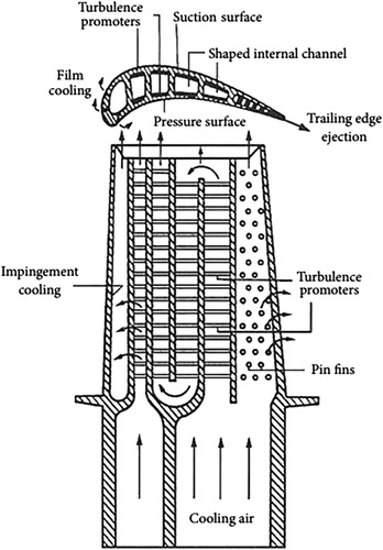
Many cooling technologies are introduced based on the high demand for the trailing edge cooling efficiency, including pin fin arrays, dimples, rib turbulator and so on [Citation2]. Pin fin arrays were proved to have the ability to enhancing the heat transfer through increasing the turbulence intensity. Besides, it can also increase the structural strength in the hollow region of the trailing edge. Metzger et al. [Citation3] and [Citation4] and Chyu et al. [Citation5] conducted a series of experiments and concluded that the height-to-diameter ratio, array orientations and inclination angle were all important factors affecting the convective heat transfer. In addition, many studies were also focusing on the effects of pin fin shapes on the heat transfer. The report from Chen et al. [Citation6] showed that drop-shaped pin fins produced a better heat transfer performance than conventional circular pin fins. Su et al. [Citation7] studied the flow structure and heat transfer performance in a rotating pin fin channel and concluded that the pin fins were very effective in enhancing the heat transfer. Zhou et al. [Citation8] studied pin fins with several different shapes (square, circular, elliptical, NACA profile, and drop-from) in a plate-pin fin heat sinks. The results showed that square-shaped pin fins not only produced the best heat transfer but also were associated with the largest friction factors. Chyu et al. [Citation9] studied the heat transfer performance of pin fins with circular, cubic, and diamond shapes. The experimental results by Chyu et al. showed that the heat transfer for pin fins with cubic and diamond shapes are better than that of pin fin with a circular shape. Wan et al. [Citation10] conducted experiments to find out the effects of pin fin cross-section shape on the heat transfer capability in a micro pin fin sink. Four kinds of shapes were studied, that is, square, circular, diamond, and streamline. They reported that square micro pin fins yielded the best boiling heat transfer. Sakanova et al. [Citation11] compared the heat transfer performance of pin fins and finned heat sinks for more-electric aircraft and concluded that the pin fin heat sink showed a distinctively better heat transfer augmentation compared to the finned heat sink.
Dimple is another good choice for heat transfer with low loss [Citation12]–[Citation15]. Dimple is designed to indent on a plain plate so as to improve the turbulence mixing and enhance the heat transfer. The flow structure visualized by Ligrani et al. [Citation16] showed that periodical shedding of the counter-rotating vortex and the secondary flow were responsible for the high turbulence intensity and heat transfer enhancement. A lot of studies focusing on the dimple shape were conducted. Turow et al. [Citation17] used large-eddy simulation (LES) to investigate the vortex structure and heat transfer in a staggered dimpled channel. The results stated that the fluctuation of the streamwise velocity and the specific vortex structure were attributable to the heat transfer augmentation. Nishda et al. [Citation18] did a series of experiments to investigate spherical and teardrop-shaped dimples and concluded that surfaces with spherical dimples yielded a better heat transfer enhancement with an increase of 20% compared with surfaces with teardrop-shaped dimples. Park et al. [Citation19] studied the heat transfer performance on surfaces with dimples with different shapes, including spherical, triangular, and titled cylinder shapes. Acharya and Zhou [Citation20] investigated the heat transfer on a dimpled surface with four dimple shapes (square, triangular, spherical, and teardrop) and reported that teardrop dimples yielded the best heat transfer augmentation. Xie et al. [Citation21] investigated the heat transfer and flow structure in a dimpled channel with various shaped dimples by a numerical method and found that spherical and ellipse-spherical dimples with long axis oriented normal to the bulk flow direction yielded the best overall performance. Rao et al. [Citation22] studied the heat transfer on a smooth surface with several different cross-section shapes of the dimples, that is, spherical, teardrop-shaped, elliptical, and inclined elliptical. According to the report, the teardrop-shaped dimples showed the best heat transfer performance. Besides, dimples were widely applied in combination with ribs [Citation23], delta winglet vortex generator [Citation24], groove [Citation25], and also pin fin [Citation26]. Luo et al. [Citation27] and [Citation28] introduced the dimple-pin fin structure into a wedge duct and carried out several numerical studies on the dimple arrangement, dimple depth, and convergence angle. Zhou et al. [Citation29] conducted experiments utilizing a high-resolution digital particle image velocimetry system to investigate the turbulent boundary layer flows over a dimpled surface.
Most studies were carried out in a stationary channel, and only a few studies were carried out under a rotating frame. However, as is well known, the airflow structure in the internal cooling passage of the rotating turbine blade is quite complicated. Despite the complex turbulence, the rotational Coriolis force also plays an important role in the heat transfer. Mohammad et al. [Citation30] performed LES calculations to studied the effects of the Coriolis force on the heat transfer and friction in a rotating channel with dimples and protrusions. The results showed that the heat transfer on the trailing side experienced a large increase in the heat transfer coefficient compared to that in a stationary channel. However, the heat transfer on the leading edge was decreased distinctively compared to that in a stationary channel. Park et al. [Citation31] experimentally investigated the heat transfer in a rotating channel with various height-to-diameter ratios of the pin fins and concluded that an increase in the height-to-diameter ratio enhanced the level of heat transfer. Later, Park et al. [Citation32] studied the heat transfer in a rotating channel with inclined pin fins. The studied inclined angles were 60° and 90°. Experimental results showed that the heat transfer decreased with the angle of inclination compared to the vertical orientation. In addition, the rotation enhanced the heat transfer compared to that in a corresponding stationary case. Chang et al. [Citation33] did a series of experiments to study the heat transfer performance in a radially rotating pin fin channel at high rotating speed and found that both the leading and trailing endwalls showed an increased heat transfer level. Besides, the heat transfer level is improved gradually with the acceleration of the rotating speed. Willett et al. [Citation34] investigated the rotation effects on heat transfer in pin fin ducts with narrow cross-sections. Kim et al. [Citation35] studied the dimple configuration effect on heat transfer coefficient in a rotating channel by experiments. The results measured by the transient liquid crystal technique showed that a dimpled surface at the trailing surface was characterized with a larger heat transfer coefficient. In addition, better heat transfer augmentation was also found for channels with deeper dimples, narrower channel, and densely distributed dimples.
Summing up the review above, it is not sufficient to study the heat transfer in a channel in a stationary coordinate system. In this study, a numerical method was utilized to study the convergence angle and dimple shape effects on the flow structure and heat transfer characteristics in a rotating pin fin-dimple wedge duct.
2. General description of the physical models
In this study, the effects of convergence angle and dimple shape on the heat transfer and flow structure in a dimpled wedge duct at different rotation numbers are studied. The general schematics of the computational model are shown in . shows the details of the physical model.
Figure 2. General schematics of the computational model.
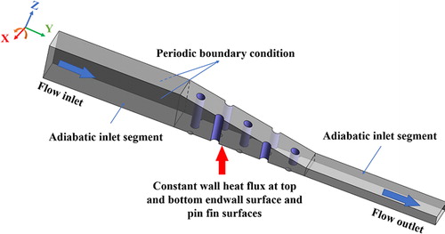
Figure 3. Detailed schematics of the computational model. (a) Wedge duct configuration; (b) Dimpled endwall configuration; (c) Pin fin and dimple configuration; (d) Dimple configuration.
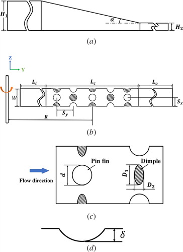
As shown in , the length of the converging segment allocated with dimples in the wedge duct is . The extended length of the inlet segment and outlet segment are
and
, respectively. The width of the wedge duct is set as
. The diameter of the circular pin fin is
. The streamwise pitch between two pin fins is
and the spanwise pitch between two pin fins is
. The dimple is located right between the pin fins with a spanwise distance
away from the pin fin. The height of the inlet segment is
. The studied converging angles are
,
, and
, corresponding to the outlet segment heights
, 30, and 48 mm as shown in . The length of the major axis and minor axis of the elliptical dimple are
and
, respectively. To ensure equal heat transfer area, the diameter of the circular dimple is set as
. The depth of the dimple is
. The ratio of the rotating radius to the pin fin diameter is
[Citation31]. The rotating axis is the x-axis as shown in . The dimpled surface becomes a leading surface when the rotating direction is counter-clockwise as shown in . In contrast, the dimpled surface becomes a trailing surface when it rotates about the rotating shaft along the clockwise direction. The cases with different dimple shapes and converging angles in the wedge duct are investigated as shown in .
Figure 4. Concept of rotation.
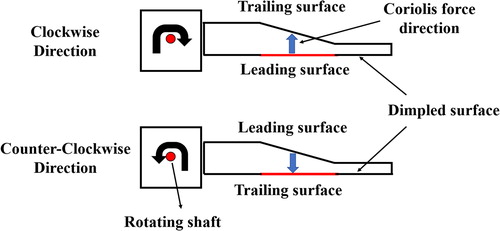
Figure 5. Comparison of the CFD results and the experimental results.
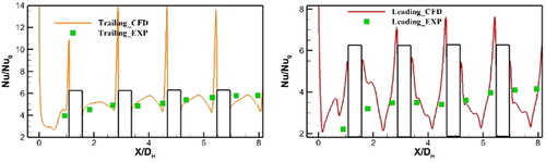
Table 1. Studied cases.
3. Computational details
3.1. Overview
Previous studies have provided confidence that the realizable turbulence model combined with an enhanced wall treat function can be chosen to calculate the steady-state, three-dimensional turbulent flow and heat transfer [Citation22]. The realizable
turbulence model [Citation36] is believed to be more powerful and precise to predict turbulent flows with flow swirling and separation and is widely used to calculate the flow motion and heat transfer in dimpled channel. The calculations and solving of governing equation were accomplished by the commercial software ANSYS FLUENT, which uses the element-based-finite volume method to solve and govern the fluid flow and heat transfer equations. The geometrical model and the computational grid are generated by an in-house code based on the MATLAB software [Citation37] and [Citation38].
3.2. Computational flow dynamics validation
The experimental results conducted by Chang et al. [Citation33] are introduced into this study and referenced. In order to improve the accuracy of the computational flow dynamics (CFD) results. shows the comparison of the area-averaged Nusselt numbers from the CFD results and experimental results. It is found that the CFD results predict the experimental results well and the deviation between the CFD results and experimental results is within acceptable range. In summary, the CFD results show a favorable match with the experimental results.
3.3. Boundary condition
In this study, the dimpled endwall, the pin fin surfaces and upper endwall surface are exposed with a constant wall heat flux . The inlet and outlet segments of the wedge duct are adiabatic. All of the surfaces are considered as no-slip boundaries. Air as an ideal gas, with a linear temperature-dependent thermal conductivity and specified viscosity, is employed as the fluid. The temperature of the air at the inlet is
. The rotation number
, as shown in EquationEq. (24)
(24)
(24) , ranges from 0.1 to 0.4. In order to reduce the computational time and reduce the computer resources, a spanwise periodic condition is applied on the side wall surfaces. High-resolution turbulence numerics and high-resolution advection scheme are employed into the study.
3.4. Governing equations
The governing equations of the heat transfer and fluid flow structure contain the conservation of mass, momentum, and energy. The equations are as follows [Citation36]
The mass conservation:(1)
(1)
The momentum conservation:(2)
(2)
The energy conservation:(3)
(3)
The turbulent kinetic energy equation and the dissipation rate
equation are:
(4)
(4)
(5)
(5)
where(6)
(6)
(7)
(7)
(8)
(8)
(9)
(9)
(10)
(10)
(11)
(11)
(12)
(12)
(13)
(13)
(14)
(14)
(15)
(15)
(16)
(16)
(17)
(17)
(18)
(18)
(19)
(19)
(20)
(20)
The constants have the values: ,
,
,
,
.
3.5. Grid details and independent solution
The model and grids for the computations are generated by an in-house MATLAB code. The grid system has a good quality of above 0.5 [Citation39]. The values at the dimpled endwall surface are maintained at approximately
. Details of the grid system are shown in . The grid independence for the computations is checked carefully for several grid systems with grid element number ranging from
to
million as shown in . The area-averaged Nusselt number of the dimpled endwall surface is almost constant when the grid element number grows from
million to
million. So, the grid system with
million grid elements is chosen for the computation.
Figure 6. The mesh details.
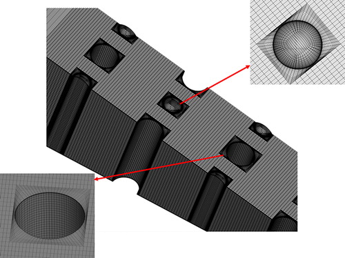
Table 2. Grid independence check.
3.6. Parameter definition
For the airflow in the studied dimple-pin fin channels, Reynolds number is defined as:(21)
(21) where,
is the density of the air at the inlet,
is the average air velocity at the inlet,
is the inlet hydraulic diameter of the wedge duct, and
is the dynamic viscosity of air at the inlet.
The heat transfer coefficient is defined as:(22)
(22) where
is the wall heat flux,
is the temperature of the endwall surface, and
is the air temperature at the inlet.
The Nusselt number is defined as:(23)
(23) where
is the thermal conductivity of air.
The rotation number is defined as:(24)
(24) where
is the rotational angular velocity.
4. Results and discussion
4.1. Effect of rotation speed and rotation direction
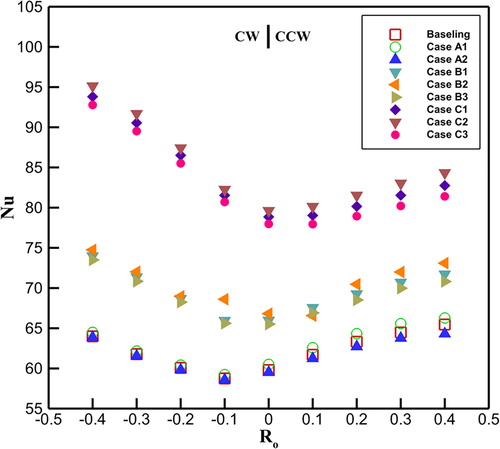
demonstrates the area-averaged Nusselt number on the dimpled surface withranging from –0.4 to 0.4. The wedge duct with negative rotation number means that the duct is rotating in the clockwise direction. While the wedge duct with positive rotation number means that the duct is rotating in the counter-clockwise direction. The increase of the Nusselt number is attributed to the increase of the rotation number. In addition, the rotation direction induces distinctive differences in the Nusselt number between the trailing dimpled endwall and leading dimpled endwall. For the Baseline, Case A1 and Case A2, which are characterized with a converging angle of
, the trailing dimpled endwall has a higher Nusselt number distribution compared with that on the leading dimpled surface. For Case B1, Case B2, and Case B3, the Nusselt numbers on the leading dimpled surface are almost identical to those on the trailing dimpled surface. However, Case C1, Case C2, and Case C3 with a
converging angle, show better heat transfer when the dimpled endwall surface is the leading side rather than the trailing side. A notable feature is that the effects of the dimple shape is becoming evident with increasing rotation number.
Figure 7. Comparison of the area-averaged Nusselt number on the dimpled endwall for ranging from -0.4 to 0.4.
4.2. Effect of convergence angle
shows the comparison of the Nusselt number distributions on the dimpled endwall for the Baseline, Case A1 and Case A2 at = 0.3. Cases with larger convergence angle show higher Nusselt number at the dimpled endwall, which means better heat transfer enhancement. Case B1 with a convergence angle of
shows an increase of 9.7% for the trailing dimpled endwall and 15.5% for the leading endwall in the area-averaged Nusselt number compared to the Baseline, respectively. Case C1 with a convergence angle of
demonstrates a distinctive increase of 26.5% for the trailing dimpled endwall and 46.6% for the leading dimpled endwall in terms of the area-averaged Nusselt number compared to the Baseline, respectively. The current findings are consistent with the area-averaged Nusselt numbers described above in .
Figure 8. Comparison of the Nusselt number distributions at the dimpled endwall surface for the Baseline, Case B1 and Case C1 at = 0.3.
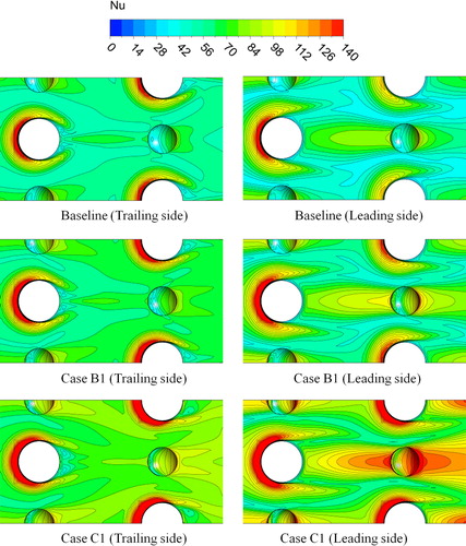
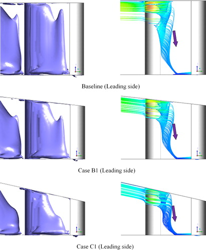
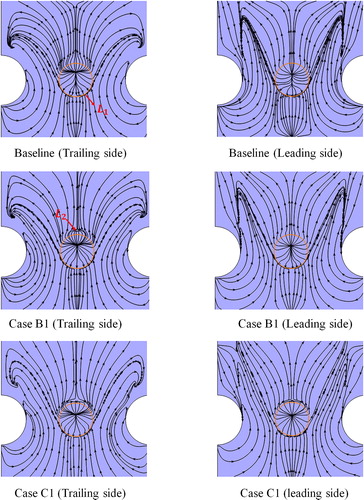
As the duct is rotating in the counter-clockwise direction, the dimpled surface is recognized as the trailing surface. Notice that a high Nusselt number region appears at the leading edge of the pin fin due to the impingement of the incoming airflow. A horseshoe vortex is induced by the adverse pressure gradient produced by the impingement. The high Nusselt number region extends to the two sides of the pin fin in the streamwise direction and forms two strip-shaped zones downstream the pin fin, which are considered to be the “legs” of the horseshoe vortex. A very interesting thing is that the high Nusselt number region in the vicinity of the pin fin is characterized by surrounding more than half of the circumference of the pin fin. There is a region with relatively low Nusselt number at the upstream half of the dimple caused by flow separation and recirculation. A region with higher Nusselt number emerges at the rear half of the dimple resulting from the airflow impingement and also the endwall surface downstream the dimple caused by flow reattachment. Especially, the Nusselt number distribution downstream the dimple shows a V-shaped band distribution which will be discussed later.
As the duct is rotating in clockwise direction, the dimpled endwall surface is treated as the leading surface. Apparently, the high Nusselt number region in the vicinity of the pin fin changes by surrounding more than half of the circumference of the pin fin to surrounding less than half of the circumference of the pin fin, which is a manifestation of the earlier shedding of the horseshoe vortex. The presence of such a phenomenon shows an excellent match with the experimental phenomenon found by Park et al. [Citation31]. A long-striped region with relative higher Nusselt number is found behind the pin fin centrally and spreads to the region downstream the dimple except for the recirculation region at the front half of the dimple which was mentioned before. The reason for this specific Nusselt number distribution is shown in . The wake behind the pin fin is transported toward the dimpled endwall. A further study about the streamlines shows that the streamlines in the wake region in the vicinity of the upper part of the pin fin move downward and impact on the dimpled endwall surface. The interaction between the two counter-rotating wake vortices near the dimpled endwall may thin the boundary layer, which is responsible for the high Nusselt number strip-shaped region behind the pin fin. In addition, the Nusselt number at the dimpled endwall treated as trailing side is higher than that on the dimpled endwall recognized as the leading side for Baseline. The reason for this is that the rotation induces a Coriolis force directed toward the trailing side of the channel. The action of the Coriolis force is responsible for pushing the more energetic flow to the trailing sides, increasing the flow rates and enhancing the heat transfer [Citation30]. However, the relation of the Nusselt number distribution between the trailing dimpled endwall and the leading dimpled endwall for Case C1 is just opposite to that in the Baseline. The leading dimpled surface provides a better heat transfer augmentation compared to the trailing dimpled surface. The Nusselt number is also consistent with the conclusion mentioned in . The reason attributed to this specific phenomenon will be discussed later.
Figure 9. Comparison of the vorticity isosurface and streamline distributions in the vicinity of the pin fin for the Baseline, Case B1 and Case B1 at = 0.3.
The streamlines give a structural view of the flow structure in the channel. shows the comparison of the streamline distributions on six cross-sectional planes along the streamwise direction at = 0.3. For counter-clockwise rotation, the dimpled endwall surface is treated as the trailing surface. For the Baseline with a convergence angle of
, a pair of counter-rotating vortices is observed inside the dimple cavity which is favorable for thinning the boundary layer and enhancing the heat transfer [Citation16]. In addition, the streamlines in the mainstream are shifted downward due to the Coriolis force. After shedding from the dimple, the vortex pair is impacted on the endwall and vanished gradually. A pair of secondary counter-rotating vortices with reversed rotating direction is induced above the endwall. Actually, the secondary vortex pair is induced by the interactive effects of the downwards flow and the counter-rotating vortex from the dimple cavity. With the increase of the convergence angle, the secondary counter-rotating vortices downstream the dimple are shrinking in size. Besides, the secondary vortex pair develops downstream further with increasing convergence angle, which is a manifestation of stronger interactive effects between the downward flow and vortex pair shed from the dimple. In other words, the secondary vortex pair in Case C1 demonstrates a less dissipative development.
Figure 10. Comparison of the streamline distributions at six planes along the streamwise direction for the Baseline, Case B1 and Case C1 at = 0.3.
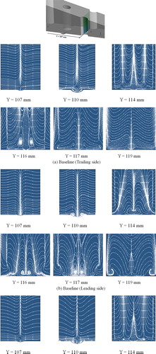
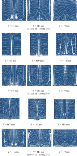
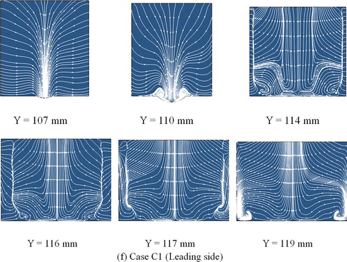
When the duct is rotating in the clockwise direction, the counter-rotating vortex changes from being concentrated at the dimple cavity to covering the dimple for the Baseline. The counter-rotating vortex is expanded in magnitude as the convergence angle is increased. Furthermore, the vortex pair is elongated downstream and lifted away from the dimpled endwall surface gradually. It should be noted that the vortex pair in cases with larger convergence angle is much shorter in the streamwise direction and vanishes from the field earlier. The downward flow is so strong that the effects of the Coriolis force are mitigated. The high energy flow is pushed toward the dimpled endwall surface by the upper endwall without dimple, leading to a distinctive heat transfer augmentation on the dimpled endwall. This specific phenomenon is in good agreement with the area-averaged Nusselt number distribution in .
describes a comparison of the limiting streamline distributions at the dimpled endwall surface for the Baseline, Case B1 and Case C1 at = 0.3. For the Baseline, a separation line emerges at the front rim of the dimple due to flow separation and recirculation. There is also a reattachment line inside the dimple cavity caused by the counter-rotating motion of the vortex pair. For Case B1 which is characterized with a convergence angle of
, a reattachment line is distributed at the endwall surface downstream the dimple for the trailing dimpled endwall surface which is solely attributed to the convergence effects. The reattachment line is mainly formed by the reattachment motion of the flow ejected out of the dimple. However, the reattachment line on the endwall surface downstream the dimple is found both at the leading dimpled endwall and the trailing dimpled endwall for Case C1. That is to say, the effect of the Coriolis force is not evident on the leading dimpled endwall and mainly offset by the stronger downward flow. Besides, the reattachment line moves upstream distinctively and closer to the rear rim of the dimple compared with the reattachment line in Case B1 Earlier reattachment is a manifestation of stronger downward flow.
Figure 11. Comparison of the limiting streamline distributions at the dimpled endwall surface for the Baseline, Case B1 and Case C1 at = 0.3.
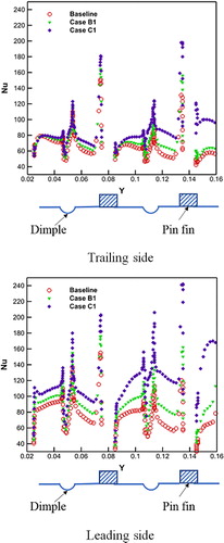
displays the Nusselt number variations along the streamwise centerline at the dimpled endwall for the Baseline, Case B1 and Case C1 at = 0.3. The Nusselt number variation for the trailing endwall surface is presented in the upper part of As shown in the figure, Case C1 with a convergence angle of
shows a gradually increasing trend of the Nusselt number and the higher Nusselt number distribution which coincidences with the conclusions in . This increasing phenomenon is absent in the other two cases. Generally, the Nusselt number behind the pin fin increases continuously and reaches a local maximum value upstream the dimple. A large drop in the value appears at the front half of the dimple caused by the flow recirculation and separation. Then the Nusselt number increases rapidly and obtains another larger local maximum value at the rear rim of the dimple attributed to flow impingement and reattachment. The highest Nusselt number appears at the leading edge of the pin fin due to the impingement. The lower part of shows the Nusselt number variation for the leading dimpled surface. A notable feature is that the differences in the Nusselt number for these three cases are much more distinctive than that on the trailing dimpled endwall. In general, the Nusselt number on the leading dimpled surface is improved a lot compared with that on the trailing dimpled surface.
Figure 12. Comparison of the Nusselt number distributions along the centerline on the dimpled endwall surface for Cases C1, C2, and C3 at = 0.3.
4.3. Effect of dimple shape
Case C1, Case C2, and Case C3 with a convergence angle of show the most distinctive difference in the area-averaged Nusselt number. So, these three cases with variously shaped dimples are chosen for the study of the effects of the dimple shape.
describes the Nusselt number distributions on the dimpled endwall surface for the Case C1, Case C2, and Case C3 at = 0.2. There is a V-shaped high Nusselt number region at the endwall surface downstream the dimple caused by the shedding of vortex pairs and flow reattachment [Citation40]. Note that Case C2 with spanwise-elliptical dimples exhibits the highest Nusselt number in the V-shaped band region. According to , Case C2 with spanwise-elliptical dimples shows an increase by 1.8% for the trailing dimpled endwall and 1.1% for the leading dimpled endwall in the area-averaged Nusselt number compared to Case C1. Case C3 with a streamwise-elliptical dimple yields a decrease by 1.5% for the trailing dimpled endwall and 1.1% for the leading dimpled endwall in the area-averaged Nusselt number compared to Case C1. The reason for this particular phenomenon is that the counter-rotating vortex induced by the spanwise-elliptical dimple is so stronger that it generates better heat transfer augmentation compared with the other kinds of dimple shapes. Case C1 with streamwise-elliptical dimples shows the smallest values. However, there is nearly no distinctive differences in the Nusselt number distributions of these three cases with differently shaped dimples when the duct is treated as the leading surface.
Figure 13. Comparison of the Nusselt number distributions on the dimpled endwall surface for Cases C1, C2, and C3 at = 0.2.
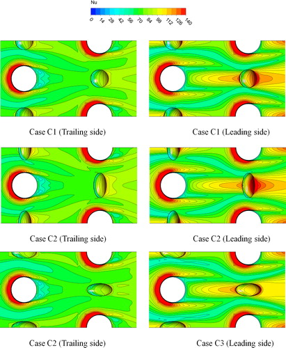
Figure 14. Comparison of the Nusselt number distributions along four spanwise lines on the dimpled endwall surface for Cases C1, C2, and C3 at = 0.2.
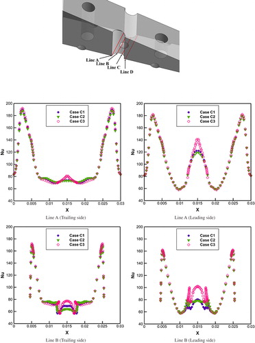
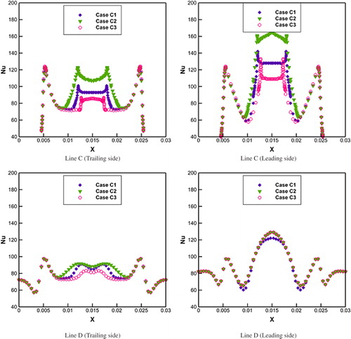
demonstrates the Nusselt number distribution along four spanwise lines at the dimpled endwall for Case C1, Case C2, and Case C3 at = 0.2. The dimpled surface is recognized as the trailing surface as the duct is rotating in the counter-clockwise direction. Originally, the highest Nusselt number are found at the leading edge of the pin fin. Case C1 shows a larger Nusselt number in the middle of the line. The Nusselt number distribution along Line B is characterized by relatively low values on the two spanwise rims of the dimple due to the flow recirculation and separation. Line C is located at the rear half or even the rear rim of the dimple, actually. The Nusselt number along Line C is much higher than that on Line B due to the flow impingement. Among these three cases, Case B1 with spanwise-elliptical dimples shows the highest Nusselt number at the middle of the dimple cavity while Case C3 shows the smallest. Line D is the spanwise line at the endwall downstream the dimple. Because of the strongest counter-rotating vortex ejected out of the dimple, Case C2 yields the highest Nusselt number values. The two local maximum values by the two sides are mainly caused by the horseshoe vortex shedding from the leading edge of the pin fin.
When the duct is rotating in the clockwise direction, the situation is changed distinctively. The Nusselt number along Line A experiences a significant increase in the middle of the duct which shows an excellent match with the discussion of . The Nusselt number distribution on Line B shows similar features with the cases when the duct is rotating in the counter-clockwise direction and two low Nusselt number points appear at the spanwise rims of the dimple due to flow recirculation. In contrast, the Nusselt number distributed on Line D shows a small but distinctive difference among these three cases. Generally, the overall Nusselt number is improved significantly compared to that on the trailing dimpled endwall surface when the duct is rotating in the counter-clockwise direction.
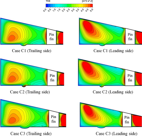
shows a comparison of the turbulence kinetic energy (TKE) distribution at a central longitudinal plane for Case C1, Case C2, and Case C3 at = 0.2. The TKE is closely related to the heat transfer. A high TKE region appears in the mainstream downstream the pin fin whose position is dependent on where the upstream flow merges [Citation41]. Besides, the TKE in the mainstream for the leading dimpled endwall is higher than that of the trailing dimpled endwall, and the location of the high-TKE region is shifted away from the dimpled surface. There is also a high TKE region at the leading edge of the pin fin due to impingement. As shown in the figure for Case A1, the location of the high-TKE region caused by flow impingement is found at the rear half of the dimple cavity for the trailing dimpled endwall, which cannot be observed when the dimpled endwall is treated as the leading surface. This location of the high-TKE region is favorable for thinning the boundary layer and enhancing the local heat transfer effectively. For Case C2 allocated with spanwise-elliptical dimple, the TKE in the vicinity of the dimple is much larger than that in Case C1 and a pea-shaped location of the high TKE region exists on both the trailing and leading dimpled endwalls. However, the high-TKE mass near the dimple in Case C3 with streamwise-elliptical dimple is hard to distinguish.
Figure 15. Comparison of the TKE distributions at the central streamwise plane for Cases C1, C2, and C3 at = 0.2.
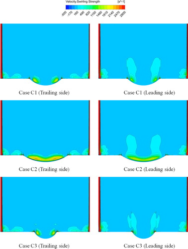
The vortex strength in the vicinity of the dimple for Case C1, Case C2, and Case C3 at = 0.2 is shown in . Case C2 with spanwise-elliptical dimples shows the strongest vortex pair both in size and intensity in the vicinity of the dimple. An additional feature is that the vortex pair for the leading dimpled endwall surface is shifted upward and away from the endwall which is mainly caused by the Coriolis force pointing toward the upper endwall. The Coriolis force is attributed for driving the vortex structure in the dimple cavity away from the dimpled endwall, which is in good agreement with the conclusion of the flow structure in .
Figure 16. Comparison of the swirling strength at the spanwise plane for Cases C1, C2, and C3 at = 0.2.
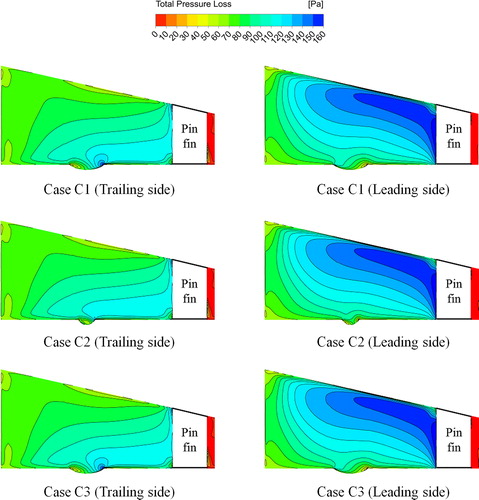
In order to reveal the pressure penalty of the dimpled duct, shows a comparison of the total pressure difference in relation to the duct inlet for Case C1, Case C2, and Case C3 at = 0.2. For the trailing dimpled endwall of these three cases, there is a location of a high-pressure penalty region appearing at the rear rim of the dimple due to the flow impingement and reattachment. This specific high-pressure loss region in Case C2 with spanwise-elliptical dimples is much smaller than that in the other two cases. In addition, the recirculation and separation zones at the front half of the dimple are characterized with a location of a low-pressure loss. For the leading dimpled endwall of these three cases, the higher-pressure penalty region in the mainstream spreads to the front rim of the dimple. In addition, a lower pressure loss region is found at the rear rim of the dimple. The pressure loss at the leading edge of the pin fin is distinctively higher resulting from impingement of the incoming air. When the dimpled endwall surface is treated as the leading surface, the highest total pressure loss emerges at the mainstream in the vicinity of the converging upper endwall. The high total pressure penalty is mainly caused by the blocking effect of the converging upper endwall.
Figure 17. Comparison of the total pressure loss at the central longitudinal plane compared to the inlet total pressure for Cases C1, C2, and C3 at = 0.2.
5. Conclusions
Rotation contributed to enhancement of the heat transfer on the dimpled endwall surface according to the numerical calculations and results. Cases with higher rotation speed showed better heat transfer on the studied endwalls with dimples.
Convergence angles contributed to the augmentation of the heat transfer. A pin fin-dimple wedge duct with larger convergence angle was closely associated with better heat transfer augmentation. The dimpled endwall as the trailing surface with a convergence angle of
showed better heat transfer augmentation than that on the dimpled endwall as the leading surface under the influence of the Coriolis force. However, Cases with a converging angle of
Spanwise-elliptical dimples exhibited the best heat transfer augmentation performance among the three kinds of dimples. That was due to the induced strong vortex structure and TKE in the vicinity of the dimple. In addition, the spanwise-elliptical dimple was characterized with a relatively low total pressure loss.
Funding
The authors acknowledge the financial support provided by the Natural Science Foundation of China (No. 51706051) and China postdoctoral science foundation funded project (No. 2017M620116), Heilongjiang Postdoctoral Fund (No. LBH-Z17066) and the Fundamental Research Funds for the Central Universities (Grant No. HIT.NSRIF.2019061).
| Nomenclature | ||
| = | Hydraulic diameter of the rectangular channel ( | |
| = | Dimple diameter ( | |
| = | Dimple diameter ( | |
| = | Pin fin diameter ( | |
| = | Friction factor | |
| = | Channel inlet height ( | |
| = | Channel outlet height ( | |
| = | Heat transfer coefficient ( | |
| = | Length ( | |
| = | Length (mm) of the inlet segment | |
| = | Length (mm) of the outlet segment | |
| Nu | = | Nusselt number |
| = | Prandtl number | |
| = | Wall heat flux ( | |
| = | Reynolds number | |
| = | Rotation number | |
| = | Distance between the dimple and pin fin in the spanwise direction | |
| = | Distance between the pin fins in the spanwise direction | |
| = | Distance between the pin fins in the streamwise direction | |
| = | Inlet air temperature ( | |
| = | Endwall surface temperature ( | |
| u | = |
|
| = | Channel width ( | |
| = | Dimple depth ( | |
| = | Thermal conductivity of air ( | |
| = | Dynamic viscosity ( | |
| = | Density of air ( | |
| = | Rotational angular velocity ( | |
Additional information
Funding
References
- J. C. Han, “Turbine blade cooling studies at Texas A&M University:1980–2004,” J. Thermophys. Heat Transfer, vol. 20, pp. 161–187, 2006.
- P. M. Ligrani, M. M. Oliveira, and T. Blaskovich, “Comparison of heat transfer augmentation techniques,” AIAA J, vol. 41, no. 3, pp. 337–362, 2003.
- D. E. Metzger, R. A. Berry, and J. P. Bronson, “Developing heat transfer in rectangular ducts with staggered arrays of short pin fins,” J. Heat Transfer, vol. 104, no. 4, pp. 700–706, 1982.
- D. E. Metzger, Z. X. Fan, and W. B. Shepard, “Pressure loss and heat transfer through multiple rows of short pin fins”, Heat Transfer 1982, Proc. 7th Int. Heat Transfer Conf., Munich, West Germany, vol.3, pp. 20–34, 1982.
- M. K. Chyu, C. H. Yen, and S. Siw, “Heat transfer in rotating channel with inclined pin-fins,” ASME J. Turbomach., vol. 133, pp. 021003, 2010.
- Z. Chen, Q. Li, D. Meier, and H. J. Warnecke, “Convective heat transfer and pressure loss in rectangular ducts with drop-shaped pin fins,” Heat Mass Transfer, vol. 33, no. 3, pp. 219–224, 1997.
- G. Su, H. C. Chen, and J. C. Han, “Computation of flow and heat transfer in rotating rectangular channels (AR =4:1) with pin-fins by a Reynolds stress turbulence model,” J. Heat Transfer, vol. 129, no. 6, pp. 685–696, 2006.
- F. Zhou, and I. Catton, “Numerical evaluation of flow and heat transfer in plate-pin fin heat sinks with various pin cross sections,” Numer. Heat Transfer, Part A, vol. 60, no. 2, pp. 107–128, 2011.
- M. K. Chyu, C. H. Yen, and S. Siw, “Comparison of heat transfer from staggered pin fin arrays with circular, cubic and diamond shaped elements”, ASME Paper No. GT2007-28306, pp. 991–999, 2007.
- W. Wan, D. Deng, Q. Huang, T. Zeng, and Y. Huang, “Experimental study and optimization of pin fin shapes in flow boiling of micro pin fin heat sinks,” Appl. Therm. Eng, vol. 114, pp. 436–449, 2017.
- A. Sakanova, and K. J. Tseng, “Comparison of pin-fin and finned shape heat sink for power electronics in future aircraft,” Appl. Therm. Eng, vol. 136, pp. 364–374, 2018.
- A. V. Schukin, A. P. Kozlov, and R. S. Agachev, “Study and application of hemispheric cavities for surface heat transfer augmentation”, ASME Paper No. 95-GT-59, pp. V004T09A034, 1995.
- V. N. Afanasyev, Y. P. Chudnovsky, A. I. Leontiev, and P. S. Roganov, “Turbulent flow friction and heat transfer characteristics for spherical cavities on a flat plate,” Exp. Therm. Fluid Sci, vol. 7, no. 1, pp. 1–8, 1993.
- G. I. Mahmood, M. L. Hill, D. L. Nelson, P. M. Ligrani, H. K. Moon, and B. Glezer, “Local heat transfer and flow structure on and above a dimpled surface in a channel,” J. Turbomach., vol. 123, no. 1, pp. 115–123, 2001.
- G. I. Mahmood, and P. M. Ligrani, “Heat transfer in a dimpled channel: combined influences of aspect ratio, temperature ratio, Reynolds number, and flow structure,” Int. J. Heat Mass Transfer, vol. 45, no. 10, pp. 2011–2020, 2002.
- P. M. Ligrani, J. L. Harrison, G. I. Mahmmod, and M. L. Hill, “Flow structure due to dimple depression on a channel surface,” Phys. Fluids, vol. 13, no. 11, pp. 3442–3451, 2001.
- J. Turnow, N. Kornev, V. Zhdanov, and E. Hassel, “Flow structures and heat transfer on dimples in a staggered arrangement,” Int. J. Heat Fluid Flow, vol. 35, pp. 168–175, 2012.
- S. Nishida, A. Murata, H. Saito, and K. Iwamoto, “Measurement of heat and fluid flow on surface with teardrop-shaped dimples”, Proceedings of Asian Congress on Gas Turbines, Tokyo, Japan, No. ACGT 2009-TS41, 2009.
- J. Park, and P. M. Ligrani, “Numerical predictions of heat transfer and fluid flow characteristics for seven different dimpled surfaces in a channel,” Numer. Heat Transfer, Part A, vol. 47, no. 3, pp. 209–232, 2005.
- S. Acharya, and F. Zhou, “Experimental and computational study of heat/mass transfer and flow structure for four dimple shapes in a square internal passage,” J. Turbomach., vol. 134, no. 6, p. 061028, 2012.
- G. Xie, J. Liu, P. M. Ligrani, and W. Zhang, “Numerical predictions of heat transfer and flow structure in a square cross-section channel with various non-spherical indentation dimples,” Numer. Heat Transfer, Part A, vol. 64, no. 3, pp. 187–215, 2013.
- Y. Rao, Y. Feng, B. Li, and B. Weigand, “Experimental and numerical study of heat transfer and flow friction in channels with dimples of different shapes,” J. Heat Transfer, vol. 137, no. 3, p. 031901, 2015.
- H. N. Jang, J. S. Park, and J. S. Kwak, “Experimental study on heat transfer characteristics in a ribbed channel with dimples, semi-spherical protrusions, or oval protrusions,” Appl. Therm. Eng., vol. 131, pp. 734–742, 2018.
- L. Luo, F. Wen, L. Wang, B. Sundén, and S. Wang, “On the solar receiver thermal enhancement by using the dimple combined with Delta winglet vortex generator,” Appl. Therm. Eng., vol. 111, pp. 586–598, 2017.
- F. Zhang, X. Wang, and J. Li, “Flow and heat transfer characteristics in rectangular channels using combination of convex-dimples with grooves,” Appl. Therm. Eng., vol. 113, pp. 926–936, 2017.
- Y. Rao, C. Wang, and S. Zang, “Comparisons of flow friction and heat transfer performance in rectangular channels with pin fin-dimple, pin fin and dimple arrays”, ASME Paper No. GT2010-22442, pp. 185–195, 2010.
- L. Luo, C. Wang, L. Wang, B. Sundén, and S. Wang, “Heat transfer and friction factor performance in a pin fin wedge duct with different dimple arrangements,” Numer. Heat Transfer, Part A, vol. 69, no. 2, pp. 209–226, 2016.
- L. Luo, C. Wang, L. Wang, B. Sundén, and S. Wang, “Heat transfer and friction factor in a dimple-pin fin wedge duct with various dimple depth and converging angle,” Int. J. Numer. Methods Heat Fluid Flow, vol. 26, no. 6, pp. 1954–1974, 2016.
- W. Zhou, Y. Rao, and H. Hu, “An experimental investigation on the characteristics of turbulent boundary layer flows over a dimpled surface,” J. Fluids Eng., vol. 138, no. 2, p. 021204, 2015.
- M. A. Elyyan, and D. K. Tafti, “Effect of Coriolis forces in a rotating channel with dimples and protrusions,” Int. J. Heat Fluid Flow, vol. 31, no. 1, pp. 1–18, 2010.
- J. S. Park, K. M. Kim, D. H. Lee, H. H. Cho, and M. K. Chyu, “Heat transfer on rotating channel with various heights of pin-fin”, ASME Paper No. GT2008-50783, pp. 727–734, 2008.
- J. S. Park, K. M. Kim, D. H. Lee, H. H. Cho, and M. K. Chyu, “Heat transfer in rotating channel with inclined pin-fins,” J. Turbomach., vol. 133, no. 2, p. 021003, 2011.
- S. W. Chang, T. Liou, T. L. Yang, and G. F. Hong, “Heat transfer in radially rotating pin-fin channel at high rotation numbers,” J. Turbomach., vol. 132, no. 2, p. 021019, 2010.
- F. T. Willett, and A. E. Bergles, “Heat transfer in rotating narrow rectangular pin-fin ducts,” Exp. Therm. Fluid Sci., vol. 25, no. 7, pp. 573–582, 2002.
- S. Kim, E. Y. Choi, and J. S. Kwak, “Effect of channel orientation on the heat transfer coefficient in the smooth and dimpled rotating rectangular channels,” ASME J. Heat Transfer, vol. 34, p. 064504, 2011.
- FLUENT, Help Document, Release 15, ANSYS, Inc., Canonsburg, PA, 2013.
- L. Luo, C. Wang, L. Wang, B. Sunden, and S. Wang, “A numerical investigation of dimple effects on internal heat transfer enhancement of a double wall cooling structure with jet impingement,” Int. J. Numer. Methods Heat Fluid Flow, vol. 26, no. 7, pp. 2175–2197, 2016.
- L. Luo, C. Wang, L. Wang, B. Sunden, and S. Wang, “Computational investigation of dimple effect on heat transfer and friction factor in a Lamilloy cooling structure,” J. Enhanced Heat Transfer, vol. 22, no. 2, pp. 147–175, 2015.
- ANSYS ICEM CFD, Reference Guide, Release 15, ANSYS, Inc., Canonsburg, PA, 2013.
- S. Wang, W. Du, L. Luo, D. Qiu, X. Zhang, and S. Li, “Flow structure and heat transfer characteristic of a dimpled wedge channel with a bleed hole in dimple at different orientations and location,” Int. J. Heat Mass Transfer, vol. 117, pp. 1216–1230, 2018.
- Y. Rao, C. Wan, and Y. Xu, “An experimental study of pressure loss and heat transfer in the pin fin-dimple channels with various dimple Dept, “h,” “s,” Int. J. Heat Mass Transfer, vol. 55, no. 23–24, pp. 6723–6733, 2012.