
 ?Mathematical formulae have been encoded as MathML and are displayed in this HTML version using MathJax in order to improve their display. Uncheck the box to turn MathJax off. This feature requires Javascript. Click on a formula to zoom.
Abstract
The realizable turbulence model was used to calculate flow and heat transfer characteristics in a rotating rectangular duct with detached pin fins in staggered arrangement. Transverse and longitudinal spacings of the pin fins were
2.5 D and
2.5 D, respectively. Reynolds number was 7,000 and Rotation number (Ro) varied from 0 to 1 while the clearance ranged from 0 to 0.5. Streamlines, vortex structure, wall shear stresses and Nusselt numbers were obtained. Flow phenomenon at the pin fin rear side and a leakage vortex near the pin fin tip were observed. High Nusselt numbers appeared on leading side. The leakage vortex imposed high energy losses in the mainflow. The flow and heat transfer characteristics were associated with Ro number and clearance. Middle values of Ro and clearance induced highest Nusselt numbers on leading side. However, high Ro and small clearance gave highest Nusselt numbers on trailing side.
1. Introduction
Turbine inlet temperature is a key parameter to evaluate the performance of a gas turbine. The higher temperature suggests a higher efficiency and output power. The sustained temperature growth had been enabled by the cooling structure development. Cooling structures such as impingement [Citation1], ribs [Citation2,Citation3], pin fins [Citation4] and film cooling [Citation5] have been widely used for vanes and blades to protect the gas turbine.
A pin fin is usually applied at the gas turbine trailing region because of the high heat transfer coefficient. Pin fins are attached perpendicular to the pressure side and suction side. A horseshoe vortex, which induces a high heat transfer coefficient, is generated at the junction between the endwall surface and pin fins [Citation6,Citation7]. According to previous studies, many parameters have notable effects on the horseshoe vortex behavior and heat transfer augmentation, such as the pin fin shape [Citation7–12], height-to-diameter ratios [Citation13], arrangement [Citation14,Citation15], fluid parameters [Citation16]. The pin fin shapes can be divided into two types. The first type of pin fin shapes has curvature continuous curves, i.e., circular shape, ellipse shape and etc. Pin fins with sharp edges (rectangle shape, triangle shape) are of the second type. According to the previous studies, the second pin fin shapes produced high heat transfer augmentation ratios accompanied by high energy loss. Due to requirement of the aerodynamic design, the trailing region has a narrow space. Therefore, the pin fin height-to-diameter ratio was from 0.5 to 4 [Citation17]. As the height-to-diameter ratio decreased, the endwall surface had greater contribution to the heat transfer than the pin fin surface [Citation13]. The pin fin arrangement also influenced the thermal performance. The arrangement had two different patterns, corresponding to the regular layout and irregular layout. The regular layout includes the inline and staggered layout [Citation14]. The staggered layout provides higher and more uniform Nusselt number distributions on the endwall surface compared to the inline ones. As for the irregular layout, such as the non-uniform distribution in the streamwise/spanwise directions [Citation18] and pentagram layout [Citation19], there is no universal conclusion for the heat transfer ability. The heat transfer ability is also sensitive to the fluid parameters. However, the academic research efforts are insufficient.
The cost of increasing the heat transfer coefficient is the increase in the friction factor in the pin fin duct. The high-pressure drop limits the use of pin fins in advanced turbine blades. Therefore, maintaining a high heat transfer coefficient with smaller pressure drop was a main research issue. A detached pin fin might be a promising technology for high thermal performance. In general, the two end sides of the pin fins are on direct contact with the endwall surface. However, there is some clearance between the one end of the pin fin and the endwall for a detached pin fin. According to previous studies, the detached pin fin provided lower friction factor than traditional pin fins. Peng et al. [Citation20] probably was the earliest researchers to study the heat transfer characteristics for a detached pin fin duct. Experimental results reported that the detached pin fin provided low friction factor and maintained a relatively high heat transfer coefficient. However, the heat transfer coefficient was decreased as the gap increased. A few years later, Steuber et al. [Citation21] also explored the heat transfer characteristics in a detached pin fin duct. The results revealed that the heat transfer ability and pressure drop were decreased simultaneously. Three different detached pin fin configurations were introduced by Arora et al. [Citation22] to experimentally investigate the Nusselt number characteristics. Results showed that the configuration with all pin fins attached to one wall provided the lowest friction factor. Dogruoz et al. [Citation23] drew the same conclusions as Sara et al. [Citation22]. Due to the limitations of the experimental measurement methods, thermocouples can only measure the heat transfer distribution at a certain point. Therefore, the detailed heat transfer characteristics were inadequate in the early studies. Since 2000, more abundant flow and heat transfer results have been displayed on the endwall surface because development of both numerical methods and experimental methods. An infrared radiometer was used to measure the heat transfer coefficients on the endwall surface by Chang et al. [Citation24]. Four different clearances (i.e., 0, 0.25, 0.5, 0.75) were introduced to study the effect of the clearance on the heat transfer. Endwall Nusselt number distributions were shown directly. The highest thermal performance was found at a clearance equal to 0.25. Moores et al. [Citation25] used thermochromics liquid crystals (TLCs) to get the heat transfer distribution on the endwall surface. Results showed that a high thermal performance was found for clearances less than 0.2. However, the highest Nusselt number occurred for C/D = 1 according to the experimental results [Citation26]. Mei et al. [Citation27] numerically studied the thermal performance in a detached pin fin duct. Numerical results showed that the heat transfer was strongly dominated by the clearance. The heat transfer was increased while the friction factor was decreased after adoption of the clearance. Jadhav et al. [Citation28] combined experimental and numerical methods to explore the heat transfer in a detached pin fin duct. Results reported that the heat transfer was sensitive to the clearance at high velocities. After adoption of the clearance, the pressure was decreased which was consistent with previous studies.
From the existing studies, it was found that the friction factor could be decreased significantly with only moderate heat transfer changes. However, these studies were for a stationary duct. For a rotating blade, the Coriolis force would alter the heat transfer distribution significantly [Citation4,Citation29–31]. However, studies of heat transfer in a rotating detached pin fin duct are limited. Therefore, it is necessary to perform research in a rotating detached pin fin duct. In this study, the effect of the rotation number and pin fin clearance on the thermal performance is investigated numerically.
2. Geometry
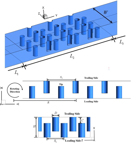
To study the influence of the rotation number (Ro) and pin fin clearance, a simplified three-dimensional rectangular duct with detached pin fins is generated according to Du et al. [Citation4], Siw et al. [Citation26] and Park et al. [Citation32]. As shown in , the rectangular channel includes seven rows of pin fins along the Y direction. The pin fin diameter is The channel height is
which is in accordance with the actual trailing region. The heated endwall length is
To obtain a fully developed turbulent flow, an addition length
is applied upstream the heated part. To decrease the effect of the outlet boundary condition, an addition length
is placed downstream the heated part. The pin fins have a staggered layout on the heated surface. The transverse spacing and longitudinal spacing are
2.5 D and
2.5 D, respectively. Five different clearances are introduced in this study, i.e.,
As the clearance
the pin fins are in contact with connects the endwall directly. The rotation radius is set as
and the Ro number is 0, 0.2, 0.4, 0.6, 0.8, 1.0.
Figure 1. Schematics diagram of rectangular channel with detached pin fins.
3. Parameter definition
The Reynolds number is defined as
(1)
(1)
where
are the cooling air density, relatively velocity, and dynamic viscosity at the inlet.
is the rectangular duct hydraulic diameter.
The Rotation number is defined as
(2)
(2)
where
is the rotational speed.
The Nusselt number is defined as
(3)
(3)
where
is the wall heat flux,
is the temperature on the endwall,
is the local bulk temperature, and
is the thermal conductivity of the cooling air.
The Q criterion about the vortex is defined as [Citation33,Citation34]
(4)
(4)
where
are the velocities in the x, y, z directions, respectively.
The dissipation function is defined as [Citation35]
(5)
(5)
4. Numerical method procedures
4.1. Mesh generation
To generate a proper structured mesh, the well known software package ICEM CFD (computational fluid dynamics) was used. It provides advanced geometry/mesh generation as well as mesh diagnostics. illustrates the overall view of the structured mesh and details of the mesh near the endwall. To capture the flow structure and make the mesh more uniform, the O-Grid is applied at the pin fin surface and endwall surface. To make sure the Y plus is around 1.0, the mesh height for the first layer is 0.01 mm. To reduce the computational demands and guarantee numerical accuracy, mesh independence verification is introduced in this study. shows the Nusselt number and wall shear stress at the leading side for Ro = 1, at different number of computational cells. For the wall shear stress, 3.0 million mesh is sufficient to obtain suitable results. However, the Nusselt number requires 4.5 million cells in the computational domain. Thus, number of computational cells is 4.5 million in this study.
Figure 2. The overall view of the structured mesh and details of mesh near the pin fin surface.
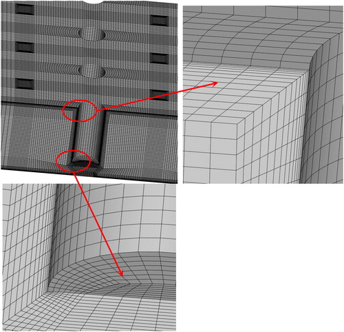
Table 1. Mesh independence.
4.2. Solution procedure and boundary conditions
A relatively velocity is used as the inlet condition, corresponding to Re = 7000 [35]. The inlet temperature and turbulence intensity are 300 K and 5%, respectively. A static pressure is used as the outlet condition. A constant wall heat flux () is used on the endwall surface and pin fin surface while an adiabatic boundary is applied on the two-additional parts. In addition, the no-slip wall condition is used for all wall.
To perform the numerical study, the commercial CFD software ANSYS FLUENT is selected to solve the incompressible three-dimensional steady flow and heat transfer [Citation36]. Cooling air is assumed as an ideal gas. To decrease the numerical dissipation and obtain more reliable results, the governing equations are discretized by second-order differences in the finite volume method in the computational domain. SIMPLE algorithm is used to handle the pressure-velocity coupling. During the computational procedure, the residuals for the continuity equation and momentum equations are less than and for the energy equation it is less than
4.3. Turbulence model selection
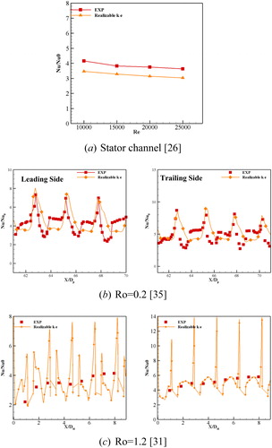
To choose a suitable turbulence model, the numerical validation covers the stationary, low rotation and high rotation numbers pin fin duct. shows the numerical validation results in details. The experimental results [Citation26] are used to verify the accuracy of the numerical method in a static detached pin fin. shows that the numerical results, which are calculated by the realizable turbulence model, are most similar to the experimental results. The maximum deviation is about 15%. For the low Ro number pin fin duct [Citation32], reveals that the realizable
turbulence model also obtains acceptable results. Especially, it has a perfect performance to predict the heat transfer at the front of pin fin. also shows that the numerical results, which are obtained by the realizable
turbulence model, agree with the experimental results [Citation31] along the flow direction. Therefore, the realizable
turbulence model is chosen to analyze the flow behavior and thermal performance in a rotating detached pin fin duct.
Figure 3. A comparison of the numerical results and experimental results.
5. Results and discussion
5.1. Overall performance
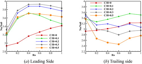
illustrates the area-averaged Nusselt number distribution on the endwall surface. shows that the Nusselt number is sensitive to the clearances and Ro number on the leading side. For the traditional pin fin (), Nusselt number on the leading side has a moderate growth from Ro = 0 to Ro = 1. This trend is consistent with previous studies [Citation4,Citation29,Citation31]. Once the clearances are introduced, the Nusselt number has a distinct increase both in a rotating duct and stationary duct. In a static duct, the highest Nusselt number is found at
then it is followed by
and
In rotating condition,
and
provide high Nusselt numbers. The relationship between Nusselt number and Ro number is also changed after adoption of the clearance. The Nusselt number shows a considerable increase in the leading side for
as the Ro number increased from 0 to 0.4. Then it experiences a diminishing trend as the Ro number is more than 0.4. shows that the trailing side provides irregular Nusselt number distribution characteristics versus Ro and clearance. For
the Nusselt number only has an obvious increase as the Ro number is increased. As a small clearance is adopted (
the Nusselt number shows a diminishing trend as the Ro number is ranging from 0 to 0.2. Then it experiences an up going trend as the Ro number is more than 0.2. The Nusselt number at
fluctuates around 3.15 as the Ro number is ranging from 0.2 to 1.0. When the
is more than 0.2, the Nusselt number shows a declining trend as the Ro is increased and reaches the lowest value at Ro = 0.6. Then the Nusselt number shows an upward trend. also reports that the highest Nusselt number is found at
and the second highest Nusselt number is found at
for Ro = 0. However, the smallest clearance
contributes to the highest Nusselt number for rotating conditions. As the clearance increases from 0 to 0.5, the Nusselt number is decreased continuously. Thus, the largest clearance
has the lowest Nusselt number.
Figure 4. Area-averaged Nusselt number distributions on the endwall surface.
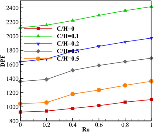
In heat transfer devices, the energy loss is very important for evaluation of the thermal performance. The pressure drop/friction factor is usually applied to quantify the energy loss in a static duct. The reason is that there is no excessive energy provided in the static duct. However, different excessive energy is supplied for the rotating channel at different Ro number. Therefore, the pressure drop/friction factor is not suitable to assess the energy loss in a rotating channel. Instead, the wall shear stress integral [Citation4] on the endwall surface and dissipation function integral on the flow domain are used to illustrate the energy loss in the rotating channel. The wall shear stress means the tangential drag force produced by viscosity and velocity gradients near the wall. The dissipation function quantity describes the irreversible transformation of mechanical energy to thermal energy. Thus, the dissipation function integral evaluates the energy loss in the whole flow domain and the wall shear stress evaluates the energy loss near the endwall surface in this study. shows a comparison of the dissipation function integral in the flow domain for different Ro number and After adoption of the clearance, the dissipation function is increased significantly. In addition, the larger clearance is responsible for the lower dissipation function. This means that the
= 0.1 induces the highest dissipation function and is followed by
= 0.2,
= 0.3, and
= 0.5. It is also found that the high Ro number induces a high dissipation function for all clearances, because a complicated fluid flow structure is generated in a rotating duct.
Figure 5. A comparison the dissipation function integral in the flow domain for different Ro numbers and C/H
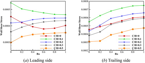
shows the wall shear stress integral on the endwall surface. shows the wall shear stress integral on the leading side. For a traditional pin fin and the smallest clearance
the wall shear stress shows a declining trend as the Ro number is increased. This trend is consistent with a previous study [Citation4]. As the clearance is more than 0.1, i.e.,
the wall shear stress is increased as the Ro number is increased. Not only the trend of the wall shear stress, but also the magnitude of the wall shear stress is sensitive to the clearance. In a static duct,
which has the smallest clearance, is in favor of the highest wall shear stress. In addition, the largest clearance leads to the smallest wall shear stress on the leading side. For a rotating condition, the
always has the highest wall shear stress while
has the smallest wall shear stress for all Ro number. The wall shear stress for
extends that in the traditional pin fin as the Ro number is more than 0.2. Compared to the wall shear stress on the leading side, the wall shear stress distribution is more regular on the trailing side, as shown in . The high Ro number promotes the wall shear stress while the large clearance suppresses the wall shear stress in a rotating duct. In addition, the cases
have a lower wall shear stress while
have a higher wall shear stress than the traditional pin fin.
Figure 6. The wall shear integral at the leading side and trailing side.
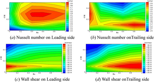
Once the detached pin fin is used in the trailing region, the clearance and Ro number should be decided based on the temperature at the trailing region. In a gas turbine, the temperature distribution is different on the pressure and suction sides due to the complex flow structure. To choose a better clearance and Ro number, shows the contour of the Nusselt number and wall shear stress versus Ro and shows the Nusselt number contours on the leading side. It is found that the low Ro number and small clearance generate a relatively low Nusselt number in the lower-left corner. The case
provides a better performance for all Ro number. From the perspective of the Ro number, the Ro number ranging from 0.4 to 0.8 leads to a higher Nusselt number. shows that the small clearance with higher Ro number should be adopted to enhance the heat transfer on trailing side in a rotating duct. In a static duct,
ranging from 0.2 to 0.4 is suggested. In addition, the largest clearance could worsen the heat transfer on the trailing side. To decrease the energy loss, the low Ro number and small clearance should be avoided on the leading side, as shown in . The case
provides the worst performance while
has the best performance for the wall shear stress. For the trailing side, the high wall shear stress is concentrated in the lower right corner, corresponding to the higher Ro number and small clearance. Relatively low wall shear stress is found at the low Ro number and larger clearances.
Figure 7. Contour of the Nusselt number and wall shear stress versus Ro and.
5.2. Ro number effect
show that the Nusselt number and energy loss are affected by the Ro number and pin fin clearance remarkably. leads to the higher Nusselt number and relatively small wall shear stress. Thus, the
is used to analyze the effect of the Ro number.
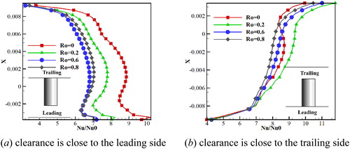
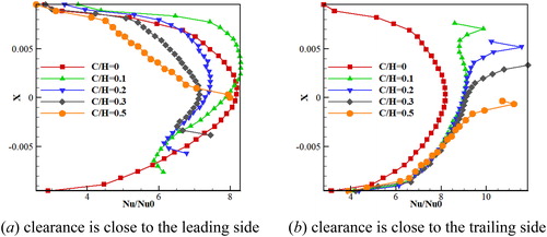
shows the circumferentially averaged Nusselt numbers on the pin fin surface along the X direction for different Ro number. Nusselt numbers on the pin fin surface, with clearance close to the leading side, are shown in . A small velocity and wake region are responsible for the lowest heat transfer augmentation at the junction between the pin fin and endwall. From the trailing side to the pin fin tip, the Nusselt number experiences an upward trend and reaches the maximums value around X = 0.002. The higher velocity and stronger impingement contribute to the upward trend. Then, Nusselt number decreases and reaches the lowest value. The higher turbulence intensity caused by the leakage flow makes the Nusselt number to increase again near the pin fin tip. Nusselt number distribution characteristics along the X direction maintain similarity while the values are changed for different Ro number. The high Ro number contributes to the low Nusselt number near the pin fin tip. The reason is that the additional fluid motion and the leakage flow, which will be displayed in the next, are changing as the Ro number is varied from 0 to 1. Furthermore, the location of the lowest Nusselt number along the X direction is closer to the pin fin tip as Ro is increased. shows the Nusselt number distribution on the pin fin surface which has the clearance near the trailing side. Excepts at Ro = 0, the Nusselt number distribution profile in is different from . shows that the Nusselt number along the X direction is almost increasing from the leading to trailing side in a rotating duct. However, the Nusselt number on the pin fin surface is decreased as the Ro number is increased.
Figure 8. Circumferentially averaged Nusselt number on the pin fin surface along the X direction for different Ro number.
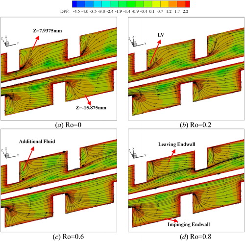
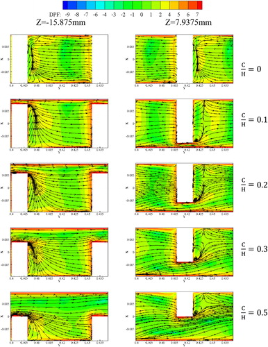
To illustrate the effect of the Ro number, a streamline and DPF distribution at different streamwise-normal planes at are displayed in . According to the previous studies, a horseshoe vortex would be generated at the core region between the pin fin and endwall both in the static duct and rotating duct [Citation37]. The horseshoe vortex transports the boundary fluid towards the main flow and brings a forward high Nusselt number. A wake region is also induced by the horseshoe vortex at the pin fin back [Citation38]. The wake region with low momentum counteracts the heat transfer augmentation. In addition, a leakage flow and a leakage vortex (LV) are found in the detached pin fin duct. The LV would bring the main flow to the pin fin back and decrease the boundary thickness on the pin fin surface. also shows that the wake region and LV are associated with the Ro number near the trailing side. The LV is large and occupies the whole wake region almost at Ro = 0. However, an additional fluid motion is produced at the pin fin back in a rotating duct [Citation4] and this changes the LV behavior significantly. At Ro = 0.2, the strength of the additional fluid motion is small and only a small region is affected near the trailing side. The additional fluid motion becomes strong while LV becomes weak near the trailing side as Ro is increased. For Ro = 0.8, the LV is invisible and the additional fluid motion occupies all the pin fin space along the X direction. As for the leading side, the LV has a small change and the additional fluid motion is invisible for all Ro number. On the other hand, the LV changes the flow direction near the endwall surface. The streamline leaves the endwall surface on the trailing side while it impinges on the leading side. The impingement is in favor of the heat transfer and the departure is bad for the heat transfer. The DPF distribution characteristics are also shown in . The highest DPF is found upstream of the pin fin because the stagnation effect. The LV also induces a higher DPF region in the mainflow due to the strong shear layer. As Ro is ranging from 0 to 1, the DPF is increased slightly at the pin fin back which has the clearance near the trailing side, while it is decreased at the back of pin fin for which the clearance is near the leading side.
Figure 9. Streamlines and DPF distributions at the streamwise-normal plane for C/H for different Ro numbers.
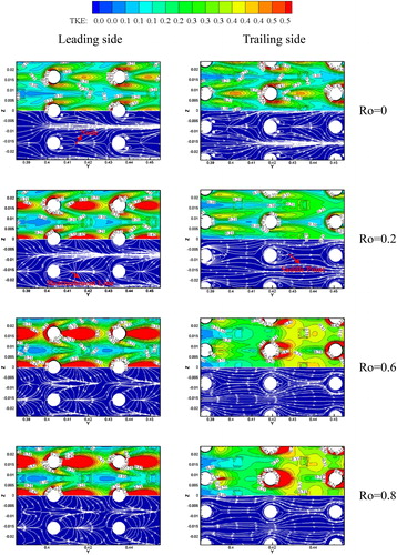
displays the limiting streamline and TKE distribution on the endwall surface for and different Ro number. The wake and horseshoe vortex are the main characteristics in a static duct. The horseshoe vortex brings a high TKE region near the pin fin surface while the wake leads to low TKE. In addition, a strong shear layer between the wake and mainflow contributes to high TKE distribution further downstream of the wake. The limiting streamline in a rotating duct is changed significantly compared to a static duct. On the leading side, the wake region disappears and a node, which is in the static duct, is occupied by a reattachment line. The reason is that the additional fluid motion impinges onto the leading side and destroys the traditional wake region. The TKE further downstream the pin fin has an obvious increase compared to that in Ro = 0. In addition, the angle between the two legs of the horseshoe vortex, corresponding to the high TKE, is increased. On the trailing side, the saddle point replaces the node near the wake region. Furthermore, the TKE near the horseshoe vortex is decreased remarkably. The reason is that the additional fluid motion makes the horseshoe vortex far away from the trailing side. However, the TKE experiences a moderate growth between the two pin fins. The streamline and TKE on the leading side is insensitive to the Ro number in a rotating duct. In contrast, the TKE distribution on the trailing side has significant changes. The wake region becomes small as the Ro number is increased accompanied by high TKE on the endwall surface.
Figure 10. Limiting streamline and TKE distributions on the endwall surface at C/H for different Ro numbers.
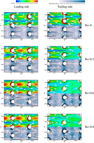
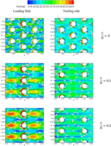
To show the Nusselt number and wall shear stress characteristics more intuitively, the Nusselt number and wall shear stress distributions on the endwall surface for different Ro number at are displayed in . In a static duct, the highest Nusselt number is found near the shear layer induced by the horseshoe vortex and main flow. The horseshoe vortex rolls up the main flow toward to the endwall surface and enhances the heat transfer [Citation24]. However, the region of the high Nusselt number is decreased along the flow direction due to the horseshoe vortex dissipation. The low Nusselt number occurs near the pin fin back, which is attributed to the low velocity and TKE. Further downstream the pin fin, a relatively higher Nusselt number region, which has the “tear” shape, occurs. This distribution characteristic is similar to the traditional pin fin duct obtained by Goldstein et al. [Citation39]. The core of the “tear” shape is located at the downstream of the junction between the wake region and mainflow. also shows that Ro number has a different effect on the Nusselt number for the leading and trailing sides. On the leading side, Nusselt number near the horseshow vortex changes slightly as Ro number is increased. However, the high Ro number induced a high Nusselt number in the tear-shaped region. In addition, the core of the tear shape moves towards the upstream. As the rotating number is more than 0.6, the wake region at the pin fin back is occupied by the tear-shaped region. On the trailing side, the tear-shaped region is invisible in a rotating duct, corresponding to the lower Nusselt number. Besides, Nusselt number is decreased around the horseshoe vortex, because the Coriolis force restricts the horseshoe vortex development on the trailing side. also shows the wall shear distribution on the endwall surface. The wall shear stress distribution on the endwall surface is also related to the Ro number. At Ro = 0, the horseshoe vortex induces a higher wall shear stress because the high-velocity gradient while the wake has the small wall shear stress on the leading side. As Ro is increased, a low wall shear stress region at the pin fin back is increased, which means that the wake region is expanded due to the additional fluid motion. On the trailing side, the high wall shear region near the pin fin is increased because the high-velocity gradient.
Figure 11. Nusselt number and wall shear distributions on the endwall surface at C/H for different Ro numbers.
5.3. Clearance effect
To explain the effect of clearance, the Ro number is kept constant (Ro = 0.4) and the clearance ranges from 0 to 0.5. shows the circumferentially averaged Nusselt numbers on the pin fin surface along the X direction with different pin fin clearances. The clearance is close to the leading side at Ro = 0.4. For the traditional pin fin, the highest Nusselt number is near X = 0 and the lowest Nusselt number is near the endwall. The reason has already been discussed in . However, the Nusslt number distribution along the X direction is asymmetric about X = 0, as shown in . The smaller clearance (promotes the heat transfer enhancement as
while it suppresses the heat transfer as
Once the
the Nusselt number on the pin fin surface is decreased compared to
For all clearances, the Nusselt number has a rising trend near the pin fin tip which is attributed to the small boundary thickness. The clearance near the trailing side leads to different Nusselt number characteristics on the pin fin surface as shown in . The Nusselt number on the pin fin surface has a remarkable increase after adoption of the clearance near the trailing side. also illustrates that the clearance only has a minimal impact on the Nusselt number as X is less than −0.004. As X is more than −0.004, the Nusselt number on the pin fin surface presents an upward trend as the clearance is increased. Furthermore, the Nusselt number is declining near the pin fin tip. This characteristic is different compared to the case when the clearance is near the leading side. The different flow direction contributes to this characteristic.
Figure 12. Circumferentially averaged Nusselt number on the pin fin surface along the X direction with different pin fin clearances at Ro = 0.4.
shows a comparison of the streamlines and DPF distribution at Ro = 0.4 for different clearances. It is found that the LV and additional fluid motion are closely associated with the clearance. In the traditional pin fin duct, a low momentum wake fluid flow is wrapped from the trailing side to the leading side by the additional fluid motion. A relatively high DPF region is induced by the additional fluid motion. After adoption of the clearance, the flow structure has significant changes. Once the clearance is used near the trailing side, the leakage fluid destroys the additional fluid motion and generates a large LV at the pin fin back. The LV transports some part of the leakage fluid from the trailing side to the leading side along the X direction. In addition, the LV changes the mainflow direction near the endwall, which has already been discussed in . As the clearance is increased, the region which is affected by the LV is expanded along the Y direction. This means that more and more fluid impinges onto the leading side and enhances the heat transfer. The clearances located on the leading side induce different flow structures compared to the case when the clearance is located on the trailing side. The leakage fluid cannot prevent the additional fluid motion generation. Thus, the additional fluid motion and LV are observed at the pin fin back. However, the additional fluid motion only affects the flow structure near the trailing side due to the LV restriction. As the clearance is increased, a saddle point, which is the symbol of a meeting position between the LV and additional fluid motion, moves towards the trailing side. also shows that the clearance has a very minor impact on the DPF at the front of the pin fin. However, the large clearance causes a small DPF between the endwall and pin fin tip.
Figure 13. Comparison the streamlines and DPF distributions at Ro = 0.4 for different clearances.
shows the limiting streamline and wall shear stress on the endwall surface at Ro = 0.4 for different clearances. Results show that the clearance has an obvious influence on the limiting streamline while it has a minor influence on the wall shear stress distribution characteristics. In the traditional pin fin duct, the limiting streamline on the leading side is similar to that in . A node is found at the junction between the wake region and main flow due to the weak additional fluid motion on the leading side. A node is gradually invisible and a reattachment line is generated on the leading side as the clearance is increased from 0 to 0.2. The reattachment line is a sign of the impingement induced by the additional fluid motion at the pin fin back. In addition, the limiting streamline on the leading side is kept similar as the clearance is increased from 0.3 to 0.5. The limiting streamline on the trailing side shows different characteristics compared to that on the leading side. A stronger leg of the horseshoe vortex is observed near the pin fin surface. A pair of the spiral point is found on the trailing side induced by the horseshoe vortex. As the clearance is increased, the leg of the horseshoe vortex is decreased. On the other hand, the wall shear stress distribution on the endwall surface is also influenced by the clearance. Due to the lack of the pin fin restriction, the wall shear stress is decreased on the endwall surface as the clearance is increased.
Figure 14. Limiting streamlines and wall shear stress on the endwall surface at Ro = 0.4 for different clearances.

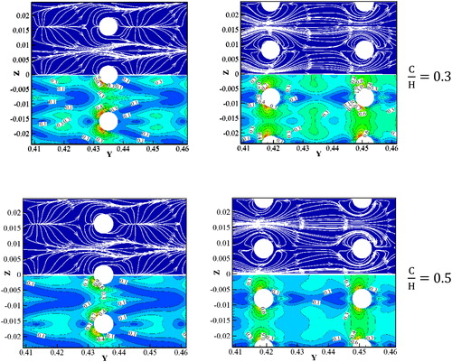
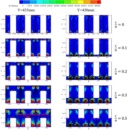
shows the streamline and Q criterion on the spanwise-normal plane at Ro = 0.4 for different clearances. In a traditional rotating pin fin duct, the leading side has a high Q value, which means a horseshoe vortex. However, the horseshoe vortex dissipation is intensive. Thus, the horseshoe vortex is invisible almost through the streamline. The horseshoe vortex dissipation becomes weak after adoption of the clearance. Therefore, the horseshoe vortex is found near the endwall in the detached pin fin duct. However, the horseshoe vortex dissipation on the trailing side is high under the Coriolis force. Therefore, the horseshoe vortex is large near the leading side. The large horseshoe vortex is beneficial for the Nusselt number on the endwall. also shows that the horseshoe vortex is increased on the leading side as the clearance continuously increases. The reason is that the pin fin restriction is decreased. On the trailing side, a small counter-rotating vortex is induced by the horseshoe vortex at the pin fin tip. As the clearance is increased, the small counter-rotating vortex is increased.
Figure 15. Streamlines and Q criterion on the spanwise-normal plane at Ro = 0.4 for different clearances.
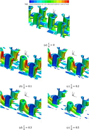
shows a comparison of the iso-vortex surfaces colored by TKE for different clearances at Ro = 0.4. The horseshoe vortex and wake region can be found through the iso-vortex surfaces in the traditional pin fin duct. In addition, the additional fluid motion induces a small iso-vortex at the pin fin back. This vortex transports the fluid from the trailing to the leading side. In addition, the trailing side presents a high TKE value. If the clearance is near the trailing side, a ring-shaped iso-vortex is found near the pin fin tip. This corresponds to a small counter-rotating vortex, as shown in . As the clearance is increased, the ring-shaped counter-rotating vortex becomes large. Besides, a pair of the LV, which causes high TKE, is found at the pin fin back. The LV merges with the wake near the leading side and turns the direction from the X to Y direction. This LV would dissipate further downstream of the pin fin ultimately. The TKE near the LV is also declining as the clearance is decreased. Once the clearance is near the leading side, the iso-vortex has a remarkable difference. The additional fluid motion will be decreased gradually from the trailing side to the leading side. The LV only leads a small iso-vortex near the pin fin tip. As the clearance is increased, the additional fluid motion changes slightly and the TKE is decreased.
Figure 16. Comparison of the iso-vortex surface colored by TKE for different clearances at Ro = 0.4.
shows the Nusselt number on the endwall surface at Ro = 0.4 for different clearances. On the leading side, a high Nusselt number region, which has a tear shape, is found at the pin fin back after using the clearance. However, the Nusselt number on the tear shape region remains constant almost as the clearance is increased from 0.1 to 0.5. In addition, the clearance has a very small influence on the Nusselt number distribution near the horseshoe vortex. On the trailing side, the Nusselt number is increased on the endwall while it is decreased near the horseshoe vortex as the clearance is increased from 0 to 0.1. As the clearance increased from 0.1 to 0.5, a relatively high Nusselt number region near the horseshoe vortex is invisible gradually. The Nusselt number on the endwall surface is also decreased as the clearance is increased. Thus, the large clearance is bad for the Nusselt number on the trailing side.
Figure 17. Nusselt number distributions on the endwall surface at Ro = 0.4.

6. Conclusions
A numerical method was introduced to explore the impact of pin fin clearance and Ro number on the heat transfer and fluid flow behavior in a pin fin duct. To enhance the credibility of the numerical method, a detailed verification and mesh independence study were carried out before the numerical study. The main numerical results are summarized as follow:
In a rotating traditional pin finned duct, a specific fluid flow was found at the pin fin back. This fluid motion impinged onto the leading side and induced a high Nusselt number. The fluid flow filed became strong as the Ro increased. Besides, the high Ro number generated a high wall shear stress and dissipation function in the pin finned duct.
A leakage vortex was generated in the detached pin fin duct. The leakage vortex destroyed the fluid motion near the trailing side. In addition, a small ring-shaped vortex was found near the pin fin tip. As the clearance increased, the leakage vortex was decreased while the ring-shaped vortex was increased. In addition, the high Ro number produced a small LV near the trailing side.
The leakage vortex induced a high dissipation function in the flow domain. As the clearance decreased and Ro number increased, the dissipation function was increased. In addition, the trailing side leads to a high wall shear stress compared to that on the leading side.
In a static duct, the pin fin clearance enhanced the heat transfer remarkable. In a rotating channel, the detached pin fin augmented the heat transfer on the leading side. However, only small pin fin clearance enhanced the heat transfer on the trailing side.
| Nomenclature | ||
| = | Clearance (mm) | |
| = | Pin fin diameter ( | |
| = | Hydraulic diameter (mm) | |
| = | Channel height ( | |
| = | Additional length before heated section ( | |
| = | Heated length ( | |
| = | Additional length after heated section ( | |
| = | Q criterion | |
| = | Wall heat flux ( | |
| = | Rotation radial ( | |
| = | Reynolds number | |
| = | Rotation number | |
| = | Transverse spacing ( | |
| = | Longitudinal spacing ( | |
| = | Wall temperature ( | |
| = | Local bulk temperature ( | |
| = | Relatively mean velocity | |
| = | Velocity in x direction | |
| = | Velocity in y direction | |
| = | Velocity in z direction | |
| = | x direction | |
| = | y direction | |
| = | z direction | |
| = | Density ( | |
| = | Dynamic viscosity ( | |
| = | Thermal conductivity ( | |
| = | Dissipation function | |
| = | Rotational speed (rad/s) | |
| Abbreviations | ||
| DPF | = | Dissipation function |
| LV | = | Leakage vortex |
| TKE | = | Turbulent kinetic energy |
| TLC | = | Thermochromics liquid crystals |
Additional information
Funding
References
- Z. Wang, Q. Zhang, Y. Yan, K. Liu, and P. M. Ligrani, “Secondary flows and extra heat transfer enhancement of ribbed surfaces with jet impingement,” Numer. Heat Transf. A-Appl., vol. 72, no. 9, pp. 669–680, 2017. DOI: 10.1080/10407782.2017.1394139.
- J. Hossain et al., “Use of rib turbulators to enhance postimpingement heat transfer for curved surface,” J. Eng. Gas Turbine Power, vol. 139, no. 7, pp. 071901, 2017. DOI: 10.1115/1.4035659.
- J. Liu, S. Hussain, J. Wang, L. Wang, G. Xie, and B. Sundén, “Heat transfer enhancement and turbulent flow in a high aspect ratio channel (4: 1) with ribs of various truncation types and arrangements,” Int. J. Therm. Sci., vol. 123, pp. 99–116, 2018. DOI: 10.1016/j.ijthermalsci.2017.09.013.
- W. Du, L. Luo, S. Wang, and X. Zhang, “Effect of the dimple location and rotating number on the heat transfer and flow structure in a pin finned channel,” Int. J. Heat Mass Transf., vol. 127, pp. 111–129, 2018. DOI: 10.1016/j.ijheatmasstransfer.2018.08.045.
- J. Wang, P. Cui, B. Sundén, and M. Vujanović, “Effects of deposition height and width on film cooling,” Numer. Heat Transf. A-Appl., vol. 70, no. 6, pp. 673–687, 2016. DOI: 10.1080/10407782.2016.1193351.
- S. Y. Won, G. I. Mahmood, and P. M. Ligrani, “Spatially-resolved heat transfer and flow structure in a rectangular channel with pin fins,” Int. J. Heat Mass Transf., vol. 47, no. 8–9, pp. 1731–1743, 2004. DOI: 10.1016/j.ijheatmasstransfer.2003.10.007.
- M. A. Moon and K. Y. Kim, “Analysis and optimization of fan-shaped pin–fin in a rectangular cooling channel,” Int. J. Heat Mass Transf., vol. 72, pp. 148–162, 2014. DOI: 10.1016/j.ijheatmasstransfer.2013.12.085.
- T. İzci, M. Koz, and A. Koşar, “The effect of micro pin-fin shape on thermal and hydraulic performance of micro pin-fin heat sinks,” Heat Transfer Eng., vol. 36, no. 17, pp. 1447–1457, 2015. DOI: 10.1080/01457632.2015.1010921.
- O. Uzol and C. Camci, “Heat transfer, pressure loss and flow field measurements downstream of staggered two-row circular and elliptical pin fin arrays,” J. Heat Transf., vol. 127, no. 5, pp. 458–471, 2005. DOI: 10.1115/1.1860563.
- N. Sahiti, A. Lemouedda, D. Stojkovic, F. Durst, and E. Franz, “Performance comparison of pin fin in-duct flow arrays with various pin cross-sections,” Appl. Therm. Eng., vol. 26, no. 11–12, pp. 1176–1192, 2006. DOI: 10.1016/j.applthermaleng.2005.10.042.
- M. K. Chyu, C. H. Yen, and S. Siw, “Comparison of heat transfer from staggered pin fin arrays with circular, cubic and diamond shaped elements,” ASME Paper No. GT2007-28306.
- F. Wang, J. Zhang, and S. Wang, “Investigation on flow and heat transfer characteristics in rectangular channel with drop-shaped pin fins,” Propulsion and Power Research, vol. 1, no. 1, pp. 64–70, 2012. DOI: 10.1016/j.jppr.2012.10.003.
- M. K. Chyu, S. C. Siw, and H. K. Moon, “Effects of height-to-diameter ratio of pin element on heat transfer from staggered pin-fin arrays,” ASME Paper No. GT2009-59814.
- T. M. Jeng and S. C. Tzeng, “Pressure drop and heat transfer of square pin-fin arrays in in-line and staggered arrangements,” Int. J. Heat Mass Transf., vol. 50, no. 11–12, pp. 2364–2375, 2007. DOI: 10.1016/j.ijheatmasstransfer.2006.10.028.
- S. A. Lawson, A. A. Thrift, K. A. Thole, and A. Kohli, “Heat transfer from multiple row arrays of low aspect ratio pin fins,” Int. J. Heat Mass Transf., vol. 54, no. 17–18, pp. 4099–4109, 2011. DOI: 10.1016/j.ijheatmasstransfer.2011.04.001.
- M. K. Chyu, Y. C. Hsing, T. P. Shih, and V. Natarajan, “Heat transfer contributions of pins and endwall in pin-fin arrays: effects of thermal boundary condition modeling,” J. Turbomach., vol. 121, no. 2, pp. 257–263, 1999. DOI: 10.1115/1.2841309.
- S. C. Lau, Y. S. Kim, and J. C. Han, “Local endwall heat/mass-transfer distributions in pin fin channels,” J. Thermophys. Heat Tranf., vol. 1, no. 4, pp. 365–372, 1987. DOI: 10.2514/3.53.
- J. K. Ostanek, and K. A. Thole, “Effects of non-uniform streamwise spacing in low aspect ratio pin fin arrays,” ASME Paper No. GT2013-95889.
- C. Bianchini, B. Facchini, F. Simonetti, L. Tarchi, and S. Zecchi, “Numerical and experimental investigation of turning flow effects on innovative pin fin arrangements for trailing edge cooling configurations,” J. Turbomach., vol. 134, no. 2, pp. 021005, 2012. DOI: 10.1115/1.4003230.
- Y. Peng, “Heat transfer and friction loss characteristics of pin fin cooling configurations,” J. Eng. Gas Turbine Power, vol. 106, no. 1, pp. 246–251, 1984. DOI: 10.1115/1.3239544.
- G. D. Steuber and D. E. Metzger, “Heat transfer and pressure loss performance for families of partial length pin fin arrays in high aspect ratio rectangular ducts,” Proc. 8th Int. Conf. Heat Transf., vol. 6, pp. 2915–2920, 1986.
- S. C. Arora and W. Abdel-Messeh, “Characteristics of partial length circular pin fins as heat transfer augmentors for airfoil internal cooling passages,” ASME Paper No. 89-GT-87.
- M. B. Dogruoz, M. Urdaneta, and A. Ortega, “Experiments and modeling of the hydraulic resistance and heat transfer of in-line square pin fin heat sinks with top by-pass flow,” Int. J. Heat Mass Transf., vol. 48, no. 23–24, pp. 5058–5071, 2005. DOI: 10.1016/j.ijheatmasstransfer.2005.07.004.
- S. W. Chang, T. L. Yang, C. C. Huang, and K. F. Chiang, “Endwall heat transfer and pressure drop in rectangular channels with attached and detached circular pin-fin array,” Int. J. Heat Mass Transf., vol. 51, no. 21–22, pp. 5247–5259, 2008. DOI: 10.1016/j.ijheatmasstransfer.2008.02.046.
- K. A. Moores, J. Kim, and Y. K. Joshi, “Heat transfer and fluid flow in shrouded pin fin arrays with and without tip clearance,” Int. J. Heat Mass Transf, vol. 52, no. 25–26, pp. 5978–5989, 2009. DOI: 10.1016/j.ijheatmasstransfer.2009.08.005.
- S. C. Siw, M. K. Chyu, T. I. P. Shih, and M. A. Alvin, “Effects of pin detached space on heat transfer and pin-fin arrays,” J. Heat Transf., vol. 134, no. 8, pp. 081902, 2012. DOI: 10.1115/1.4006166.
- D. Mei, X. Lou, M. Qian, Z. Yao, L. Liang, and Z. Chen, “Effect of tip clearance on the heat transfer and pressure drop performance in the micro-reactor with micro-pin–fin arrays at low Reynolds number,” Int. J. Heat Mass Transf., vol. 70, pp. 709–718, 2014. DOI: 10.1016/j.ijheatmasstransfer.2013.11.060.
- R. S. Jadhav and C. Balaji, “Fluid flow and heat transfer characteristics of a vertical channel with detached pin-fin arrays arranged in staggered manner on two opposite endwalls,” Int. J. Therm. Sci., vol. 105, pp. 57–74, 2016. DOI: 10.1016/j.ijthermalsci.2016.02.017.
- W. Du, L. Luo, and S. Wang, “Effect of dimple/protrusion depth on flow structure and heat transfer in a rotating channel with pin fin,” ASME Paper No. GT2018-76158.
- J. C. Han, “Fundamental gas turbine heat transfer,” J. Therm. Sci. Eng. Appl., vol. 5, no. 2, pp. 021007, 2013. DOI: 10.1115/1.4023826.
- S. W. Chang, T. M. Liou, T. L. Yang, and G. F. Hong, “Heat transfer in radially rotating pin-fin channel at high rotation numbers,” J. Turbomach., vol. 132, no. 2, pp. 021019, 2010. DOI: 10.1115/1.3147103.
- J. S. Park, K. M. Kim, D. H. Lee, H. H. Cho, and M. K. Chyu, “Heat transfer on rotating channel with various heights of pin-fin,” ASME Paper No. GT2008-50783.
- Y. Dubief and F. Delcayre, “On coherent-vortex identification in turbulence,” J. Turbul., vol. 1, pp. 11, 2000. DOI: 10.1088/1468-5248/1/1/011.
- G. Haller, “An objective definition of a vortex,” J. Fluid Mech., vol. 525, pp. 1–26, 2005. DOI: 10.1017/S0022112004002526.
- H. Schlichting and K. Gersten, boundary layer theory – 8th revised and enlarged edition, Berlin: Springer, pp. 70–73, 2000.
- ANSYS FLUENT, Reference Guide, Release 15 (2013).
- G. Su, H. C. Chen, and J. C. Han, “Computation of flow and heat transfer in rotating rectangular channels (AR= 4: 1) with pin-fins by a Reynolds stress turbulence model,” J. Heat Transf., vol. 129, no. 6, pp. 685–696, 2007. DOI: 10.1115/1.2717935.
- A. Armellini, L. Casarsa, and P. Giannattasio, “Separated flow structures around a cylindrical obstacle in a narrow channel,” Exp. Therm. Fluid Sci., vol. 33, no. 4, pp. 604–619, 2009. DOI: 10.1016/j.expthermflusci.2008.12.005.
- R. J. Goldstein, M. K. Chyu, and R. C. Hain, “Measurement of local mass transfer on a surface in the region of the base of a protruding cylinder with a computer-controlled data acquisition system,” Int. J. Heat Mass Transf., vol. 28, no. 5, pp. 977–985, 1985. DOI: 10.1016/0017-9310(85)90279-0.