
 ?Mathematical formulae have been encoded as MathML and are displayed in this HTML version using MathJax in order to improve their display. Uncheck the box to turn MathJax off. This feature requires Javascript. Click on a formula to zoom.
Abstract
This study aims to investigate the cooling performance of various film cooling holes, including combined hole, cylinder hole, conical hole, and fan-shaped hole. For film cooling technology, a novel combined hole configuration is first proposed to improve the cooling protection for gas turbine engines. This combined hole consists of a central cylinder hole (an inclination angle of 35°) and two additional side holes (a lateral diffusion angle of 30°). Film holes for four-hole configurations have the same inlet diameter of 8 mm. The adiabatic film cooling effectiveness for each hole configuration is analyzed for varying blowing ratios (M = 0.25, 0.5, 0.75, and 1.0). Results show that the best cooling performance for the conical and fan-shaped holes is obtained at the blowing ratio of 0.75. In addition, the combined hole configuration provides a more uniform cooling protection and a better cooling performance than the other hole configurations.
1. Introduction
In the last 50 years, inlet temperature of gas turbine engines was increased with the requirement of high thermal efficiency. To ensure that the turbine engines are running in a safe and efficient condition, directional solidification and single crystal technology of nickel-based superalloys were applied to turbine vanes to withstand high temperature environments [Citation1]. Based on large eddy simulation, Tafti et al. [Citation2] investigated how to improve heat transfer performance of turbine blades. They found that it is a significant enhancement on heat transfer by equipping ribs on the turbine vanes. However, the equipped ribs result in the increase of the rotating centrifugal force. Film cooling technology, as a major cooling technology, becomes one of commonly used techniques to prevent the blade surfaces from the hot mainstream. Han and Ekkad [Citation3] analyzed the external blade cooling technology and summarized the development of the film cooling in the last century. In addition, Sunden and Xie [Citation4] reviewed the film cooling technology in the blade tip region during 2001–2008.
Film cooling effectiveness is affected by many factors, such as blowing ratio, injection angle, film-hole configuration, etc. Kusterer et al. [Citation5] investigated the effect of kidney vortices on cooling performance using double-jets. They indicated that the novel double-jet hole provided a good cooling performance even at high blowing ratios (M = 1.7 and 2.0). Rozati and Tafti [Citation6] found that the high blowing ratio strengthened the mixing between the coolant air and the hot mainstream, and the cooling performance downstream the wall was weakened. Benson et al. [Citation7] found that the film cooling effectiveness at the trailing edge was improved at a high blowing ratio. Based on a three-dimensional blade model, Kianpour et al. [Citation8] numerically investigated an effect of blowing ratio on film cooling effectiveness. They found that the coverage layer of the coolant air is growing slightly with increasing the blowing ratio from 1.25 to 3.18. Wang et al. [Citation9] conducted an investigation of film holes with a compound angle of 45° on film cooling performance, and they found that the compound angle provided a uniform cooling protection downstream the wall. Singh et al. [Citation10] performed a numerical study over a flat plate to analyze the effect of the temperature ratio on the film cooling/film heating effectiveness. They pointed out that the film heating cannot be considered analogous to film cooling when high density ratio was used. After a numerical calculation on a two-dimensional waved surface, Singh et al. [Citation11] showed that an injection angle of 60° provided the highest effectiveness at all blowing ratios (M = 1, 2, and 3) and density ratios (0.2–5.0).
Furthermore, the film-hole configuration has great influence on cooling protection of turbine blades. However, the conventional cylindrical hole provides a narrow coverage area of the coolant air, which decreases the lateral-averaged film cooling effectiveness downstream the wall. Cylindrical holes in a slot showed a significant enhancement of lateral adiabatic effectiveness [Citation12]. Lee and Kim [Citation13] found that the maximum film cooling effectiveness was obtained by using a trench height of 1.0 hole diameter and a downstream trench width of 0.25 diameter. Bunker [Citation14] conducted a survey of effects of various shaped holes on film cooling, and it was found that shaped film holes with expanded exits had low sensitivity to free-stream turbulence intensity variations. Ely and Jubran [Citation15] investigated a sister hole cooling technique using large inclination angle, and results showed that the sister hole provided better performance at given blowing ratios than a single hole. Khajehhasani and Jubran [Citation16] also found that the sister hole configuration provides a higher lateral film cooling effectiveness. An et al. [Citation17] designed a novel shaped hole based on the exit edge with a middle bulge, and they showed that the streamwise diffusion structure on the hole exit enlarged the film cooling coverage width greatly and increased the film cooling effectiveness significantly. Dai et al. [Citation18] conducted a comparison of four film cooling holes using the Reynolds-averaged Navier–Stokes (RANS) analysis for various blowing ratios (M = 0.5, 1.0, 1.5, and 2.0). Results showed that the kidney vortices were suppressed by the auxiliary holes, which offered a better cooling protection. Gao et al. [Citation19] performed an experimental study to reveal the effect of axial discrete holes on film cooling effectiveness. They indicated that the axial angled fan-shaped holes provided a better lateral film cooling performance. Mazaheri et al. [Citation20] combined a modified heat-flux model with the Gibson-Launder (GL) second-moment closure (SMC) model to obtain reliable results for film cooling at a high blowing ratio. Zhou et al. [Citation21] numerically investigated effects of various film-hole configurations on film cooling effectiveness with mist injection. They found that the console hole offered the best coolant coverage rate compared with the shaped and cylindrical holes.
A novel combined hole is first proposed in this article. This new configuration includes an inclination cylinder hole in the centerline and two additional side holes with a lateral diffusion angle of 30°. A comparison of film cooling performances is carried out based on many hole configurations, i.e., the combined hole, cylindrical hole, conical hole, and fan-shaped hole. The steady-state Navier-Stokes equations are solved to analyze the film cooling effectiveness with various blowing ratios (M = 0.25, 0.5, 0.75, and 1.0).
2. Governing equations
The standard k-ε turbulence model with enhanced wall treatment is used to solve the steady-state Navier-Stokes equations in this study. The governing equations of mass, momentum, energy, the turbulent kinetic energy, and the dissipation rate are shown as follows:
(1)
(1)
(2)
(2)
(3)
(3)
(4)
(4)
(5)
(5)
where the Sm, Fj and Sh are the source terms of the mass, momentum, and energy equations. The symmetric stress tensor is represented by τij. μϕ, and λ represent the dissipation heat and the effective thermal conductivity, respectively.
The terms of
and μt in the above equations represent the Reynolds stresses, the turbulent heat fluxes and the turbulent viscosity, respectively. The calculation equations are given as follows:
(6)
(6)
(7)
(7)
(8)
(8)
The model constants have the following default values:
(9)
(9)
More details about the governing equations can be found in Refs. [Citation22, Citation23].
3. Physical model and validation
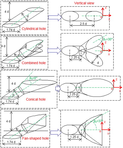
The computational domain for numerical simulations is shown in . The used domain has dimensions of 40 d × 10 d × 4 d. As shown in , four-hole configurations are considered in this article, including cylindrical hole, combined hole, conical hole, and fan-shaped hole. For all hole configurations, the central film hole has a forward inclination angle (α) of 35° in the middle section, and the inlet of the film hole has the same initial diameter (d = 8 mm). The combined hole has no lateral angle, whereas the combined hole configuration has two additional side holes with a lateral diffusion angle of 30°. The combined hole configuration is formed by a combination of three cylindrical holes with the same diameter. For the conical hole configuration, the flow passage for the coolant air changes from a cylindrical shape to a conical shape at x = 1.25 d in a top view. The fan-shaped hole has a lateral diffusion angle of 37°. Moreover, four-hole configurations are investigated to find the optimal film cooling hole at various blowing ratios (M = 0.25, 0.5, 0.75, 1.0).
Figure 1. Schematic of computational domain.
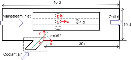
Figure 2. Four-hole configurations.
shows the boundary conditions for the numerical simulations. The inlet temperatures of the mainstream and the coolant air are 400 and 300 K, respectively. The mainstream has a uniform velocity of 10 m/s. Symmetrical boundary and no-slip conditions are set at the side walls and other walls, respectively.
Table 1. Boundary conditions.
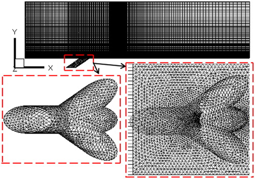
shows the grid meshes for the case with the combined hole. Unstructured grids are used inside the film hole and in the near-hole region, whereas structured grids are applied to the rest of the computational domain. In the near wall region, the first cell nodes are placed with y+ ≈ 1. The software ANSYS FLUENT 16.2 is adopted to predict the simulated results. Each case has residuals of 10–6 for all the results, and above 2000 iterations are necessary to complete the simulations.
Figure 3. Mesh view.
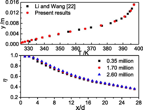
Three grid cases with 0.35, 1.70, and 2.60 million cells are investigated to determine the optimal number of grid meshes as shown in . For the case with 1.70 million cells, values of the film cooling effectiveness on the centerline overlap with those for the case with 2.60 million cells. The case with 0.35 million cells shows lower cooling effectiveness than the other cases from x = 4 to 12 d. Finally, the case with 1.70 million cells was selected for the present research. The standard k–ε turbulence model with the enhanced wall treatment was used as shown in Ref. [Citation22]. The present research shows mostly overlapping values of the temperature distribution along the centerline compared with the results from Ref. [Citation22].
Figure 4. Model validation and grid independence study.
4. Results and discussion
4.1. Comparison of hole configurations
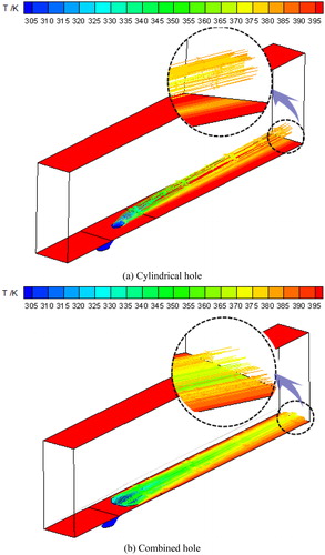
shows streamlines and temperature distributions for the cylindrical and combined hole configurations at M = 1.0. With the same inlet of the coolant air, the combined hole case shows a wider coverage area of film cooling protection compared with the cylindrical hole case. Moreover, the coolant air for the combined hole case moves close to the wall, whereas a majority of the coolant air for the cylindrical hole case lifts off the wall as shown by the dotted line. When the combined hole is used instead of the cylindrical hole, a better film cooling effectiveness is provided even near the outlet of the computational domain.
Figure 5. Streamlines and temperature distributions for two hole configurations, M = 1.0.
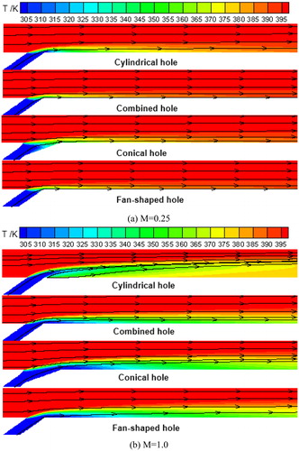
Streamlines and temperature contours at the middle sections for M = 0.25 and 1.0 are shown in . For the cylindrical hole case at M = 0.25, a good cooling protection is obtained downstream the wall. When compared with the cylindrical hole case, the coolant air for the conical hole case shows a smaller affected area. When the blowing ratio increases to 1.0, the coolant air for the cylindrical hole case is injected into the mainstream, and liftoff of the coolant air results in a reduction of the film cooling effectiveness. Compared with the other three cases, the conical hole configuration provides the best film cooling effectiveness on the centerline especially near the outlet of the film hole. This is because the conical hole configuration has an extended slope which increases the coolant air velocity along the wall. To obtain a good cooling performance on the centerline, it is recommended to use the cylindrical hole configuration for M = 0.25 and the conical hole configuration for M = 1.0.
Figure 6. Streamlines and temperature contours on middle sections at M = 0.25 and 1.0.
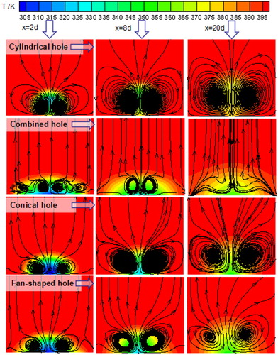
To obtain more flow information, shows streamlines on different cross-sections at M = 1.0. For the cylindrical hole case, a vortex pair with a kidney shape forms near the film hole, when the coolant air is injected into the mainstream. More flowing space downstream the wall is involved due to an extension of this vortex pair. When compared with the cylindrical hole case, flow distributions for the conical hole and fan-shaped hole cases are slightly affected by the mainstream, and the occupied area by the coolant air becomes smaller. When compared with the other three hole configurations, the combined hole configuration provides a lower temperature distribution close to the wall, and a second smaller vortex pair forms besides the kidney-shaped vortex pair at x = 2 d. This indicates that the coolant air out of the combined hole shows a better cooling performance than the other cases.
Figure 7. Streamlines and temperature contours on different cross-sections, M = 1.0.
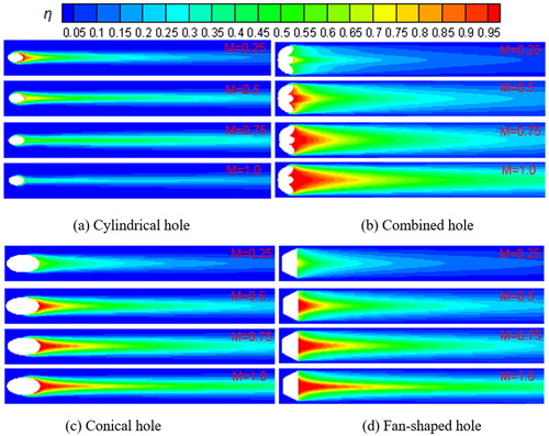
A comparison of the wall film cooling effectivenesses for the four-hole configurations is presented in . The cylindrical hole case with a blowing ratio of 0.25 shows a better cooling performance on the centerline than the other three cases, whereas the lateral film cooling effectiveness has the smallest coverage area of cooling protection compared with the other three cases. The combined and fan-shaped holes provide a similar cooling protection, and these two configurations at low blowing ratio present better film cooling effectiveness than the cylindrical and conical hole configurations. For most cases (except the cylindrical hole case), the film cooling effectiveness increases with the increase of the blowing ratio (from 0.25 to 1.0). For the blowing ratio of 1.0, the best downstream and lateral cooling performance is obtained by using the combined hole configuration. From the results, it is concluded that a comprehensive film cooling effectiveness (both downstream and lateral values) is achieved by using the combined hole configuration instead of the cylindrical one.
Figure 8. Wall film cooling effectiveness for four-hole configurations with different blowing ratios.
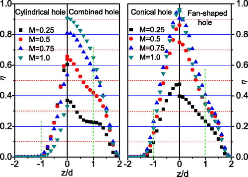
shows the lateral film cooling effectiveness for four-hole configurations with different blowing ratios at x = 3 d. For the cylindrical hole case with the blowing ratio of 0.25, the lateral distribution of the film cooling effectiveness shows a similar trend to that with the blowing ratio of 0.5. It is found that values of the film cooling effectiveness are close to zero at |z| < 1 d. The lateral film cooling effectiveness for the cylindrical hole case decreases with the increase of the blowing ratio. However, all the values of the film cooling effectiveness are above 0.2 at |z| < 1 d. Moreover, the combined hole shows a reverse trend as the lateral film cooling effectiveness increases with the blowing ratio compared with the cylindrical hole. For the conical and fan-shaped hole cases an optimal cooling performance is obtained at the blowing ratio of 0.75. When compared with the other three cases, the combined hole provides a better cooling protection near |z| = 1 d.
Figure 9. Lateral film cooling effectiveness for four-hole configurations with different blowing ratios, x = 3 d.
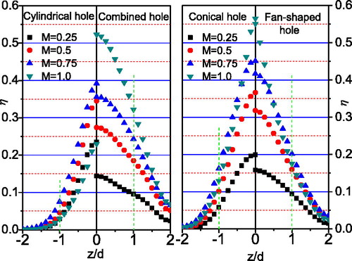
To investigate the effect of various hole configurations along the wall, the lateral film cooling effectiveness at x = 15 d is presented in . When compared with the results at x = 3d, the lateral distribution of the film cooling effectiveness at x = 15 d for the cylindrical hole case shows higher values near |z| = 1 d. However, the cylindrical hole case has lower values of the film cooling effectiveness at x = 15 d than at x = 3 d. From and , it is evident that the cylindrical hole provides worse lateral cooling protection than the other three configurations. In all of these hole configurations with blowing ratios of 0.25–1.0, the combined hole has the best lateral cooling performance along the lateral direction (except near the wall centerline). This indicates that the combined hole shows a distinct advantage on the lateral cooling protection on the wall surface.
Figure 10. Lateral film cooling effectiveness for four-hole configurations with different blowing ratios, x = 15 d.
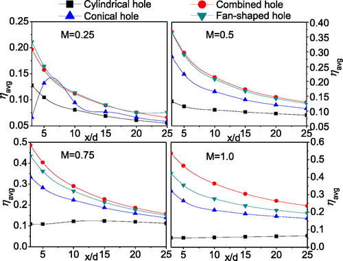
In order to evaluate the overall cooling performance, the lateral-averaged film cooling effectiveness downstream the wall is investigated in . When compared with other hole configurations at M = 0.25, the conical hole case shows the lowest values of the lateral-averaged film cooling effectiveness upstream x = 5 d. Considering the cases with various hole configurations, the best cooling performance for the blowing ratios of 0.5–1.0 is obtained by using the cylindrical hole. This indicates that the film-hole configuration, both the passage of the coolant air and the outlet shape of the film hole, shows a significant effect on the flow field and the temperature distribution downstream the wall.
Figure 11. Lateral-averaged film cooling effectiveness for four-hole configurations with various blowing ratios.
4.2. Non-uniformity distribution
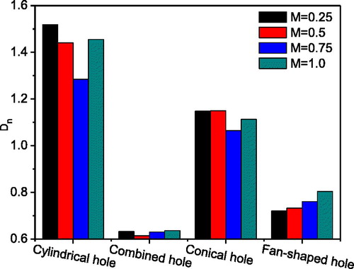
The non-uniformity of the film cooling effectiveness distribution was first quantitatively discussed by using a parameter (Dn) in Ref. [Citation9]. This parameter provides an effective method to analyze the cooling protection for the wall surface, and it is defined as
(10)
(10)
where N is the number of grid nodes on the wall. ηi is the wall film cooling effectiveness at the grid node i, ηa is the averaged wall film cooling effectiveness, respectively.
shows the non-uniformity of the film cooling effectiveness distribution downstream the wall for various hole configurations. A high value of Dn shows a high non-uniformity level, which means an uneven cooling performance. It is found that the non-uniformity distribution for the combined hole configuration has the lowest values compared with the other configurations. This indicates that the film cooling effectiveness for the combined hole configuration shows a balance of benefits between the lateral direction and along the wall. This is beneficial for obtaining a more uniform temperature distribution, which can reduce the concentration of thermal stress on the wall surface.
Figure 12. Non-uniformity distribution (Dn) for different hole configurations and blowing ratios.
5. Conclusions
In this article, a novel combined hole configuration was first proposed to investigate the film cooling performance by comparison with other three existing hole configurations (cylindrical hole, conical hole, fan-shaped hole) over a flat plate. Finally, the distribution non-uniformity of the film cooling effectiveness was analyzed at four blowing ratios. The conclusions can be summarized as follows:
In the vicinity of the hole outlet, the conical hole configuration offers the best film cooling effectiveness on the centerline compared with the other three configurations, and this is because the extended slope of the conical hole increases the velocity of the coolant air. The conical and fan-shaped hole cases show the best cooling performance at the blowing ratio of 0.75.
The film cooling effectiveness increases with the increase of the blowing ratio (from 0.25 to 1.0) for the combined, fan-shaped and conical holes. The combined and fan-shaped holes contribute to a better film cooling than the cylindrical and conical holes at low blowing ratio. For the blowing ratio of 1.0, the highest downstream and lateral values of the film cooling effectiveness are obtained by using the combined hole configuration.
For the considered blowing ratios (from 0.25 to 1.0), the combined hole configuration shows the lowest values of non-uniformity of the distribution compared with the other configurations. This result indicates that the combined hole configuration provides a uniform film cooling performance both in the downstream and lateral directions, which results in a reduction of the thermal stress concentration on the wall surface.
| Nomenclature | ||
| cp | = | specific heat, J/kg K |
| Dn | = | nonuniformity distribution |
| d | = | film hole throat diameter, m |
| k | = | turbulent kinetic energy, m2/s2 |
| M | = | blowing ratio, (ρjVj) / (ρ∞V∞) |
| S, F | = | source term |
| T | = | temperature, K |
| u | = | streamwise velocity component, m/s |
| V | = | velocity magnitude, m/s |
| x, y, z | = | coordinate direction distance, m |
| Greek symbols | ||
| α | = | inclination angle, deg. |
| β | = | diffusion angle, deg. |
| ε | = | turbulence dissipation rate, m2/s3 |
| η | = | adiabatic film cooling effectiveness, (Taw–Ti)/(Tj–Ti) |
| λ | = | thermal conductivity, W/m K |
| μ | = | dynamic viscosity, kg/m s |
| ρ | = | density, kg/m3 |
| τ | = | stress tensor, N/m2 |
| Subscripts | ||
| a | = | area average value |
| aw | = | adiabatic wall |
| c | = | centerline |
| i | = | mainstream flow |
| j | = | coolant air |
| t | = | turbulent |
Additional information
Funding
References
- P. Caron and T. Khan, “Evolution of Ni-based superalloys for single crystal gas turbine blade applications,” Aerospace Sci. Technol., vol. 3, pp. 513–523, 1999. DOI: 10.1016/S1270-9638(99)00108-X.
- D. K. Tafti, L. He, and K. Nagendra, “Large eddy simulation for predicting turbulent heat transfer in gas turbines,” Philos. Trans A Math. Phys. Eng. Sci., vol. 372, no. 2022, pp. 20130322, 2014. DOI: 10.1098/rsta.2013.0322.
- J. C. Han and S. Ekkad, “Recent development in turbine blade film cooling,” Int. J. Rotating Mach., vol. 7, no. 1, pp. 21–40, 2001. DOI: 10.1155/S1023621X01000033.
- B. Sundén and G. N. Xie, “Gas turbine blade tip heat transfer and cooling: A literature survey,” Heat Transf. Eng., vol. 31, pp. 527–554, 2010. DOI: 10.1080/01457630903425320.
- K. Kusterer, D. Bohn, T. Sugimoto, and R. Tanaka, “Influence of blowing ratio on the double-jet ejection of cooling air,” presented at the ASME Turbo Expo 2007: Power for Land, Sea, and Air, Montreal, Canada, May 14–17, 2007, pp. 305–315.
- A. Rozati and D. K. Tafti, “Effect of coolant–mainstream blowing ratio on leading edge film cooling flow and heat transfer–LES investigation,” Int. J. Heat Fluid Flow, vol. 29, pp. 857–873, 2008. DOI: 10.1016/j.ijheatfluidflow.2008.02.007.
- M. J. Benson, C. J. Elkins, S. D. Yapa, J. B. Ling, and J. K. Eaton, “Effects of varying reynolds number, blowing ratio, and internal geometry on trailing edge cutback film cooling,” Exp. Fluids, vol. 52, no. 6, pp. 1415–1430, 2012. DOI: 10.1007/s00348-012-1260-1.
- E. Kianpour, N. A. C. Sidik, and I. Golshokouh, “Measurement of film effectiveness for cylindrical and row trenched cooling holes at different blowing ratios,” Numer. Heat Transf. A Appl., vol. 66, no. 10, pp. 1154–1171, 2014. DOI: 10.1080/10407782.2014.901042.
- J. Wang, C. Gu, and B. Sundén, “Investigations of film cooling and its nonuniform distribution for the conjugate heat transfer passage with a compound inclined angle jet,” Numer. Heat Transf. A Appl., vol. 69, no. 1, pp. 14–30, 2016. DOI: 10.1080/10407782.2015.1023156.
- K. Singh, B. Premachandran, M. R. Ravi, B. Suresh, and S. Vasudev, “Prediction of film cooling effectiveness over a flat plate from film heating studies,” Numer. Heat Transf. A Appl., vol. 69, no. 5, pp. 529–544, 2016. DOI: 10.1080/10407782.2015.1090232.
- K. Singh, B. Premachandran, and M. R. Ravi, “Numerical investigation of film cooling on a 2d corrugated surface,” Numer. Heat Transf. A Appl., vol. 70, no. 11, pp. 1253–1270, 2016. DOI: 10.1080/10407782.2016.1230431.
- S. B. Islami, S. P. A. Tabrizi, and B. A. Jubran, “Computational investigation of film cooling from trenched holes near the leading edge of a turbine blade,” Numer. Heat Transf. A Appl., vol. 53, no. 3, pp. 308–322, 2007. DOI: 10.1080/10407780701564200.
- K. D. Lee and K. Y. Kim, “Film cooling performance of cylindrical holes embedded in a transverse trench,” Numer. Heat Transf. A Appl., vol. 65, no. 2, pp. 127–143, 2014. DOI: 10.1080/10407782.2013.826106.
- R. S. Bunker, “A review of shaped hole turbine film-cooling technology,” J. Heat Transf., vol. 127, no. 4, pp. 441–453, 2005. DOI: 10.1115/1.1860562.
- M. J. Ely and B. A. Jubran, “A numerical study on improving large angle film cooling performance through the use of sister holes,” Numer. Heat Transf. A Appl., vol. 55, no. 7, pp. 634–653, 2009. DOI: 10.1080/10407780902821532.
- S. Khajehhasani and B. Jubran, “Numerical assessment of the film cooling through novel sister-shaped single-hole schemes,” Numer. Heat Transf A Appl., vol. 67, no. 4, pp. 414–435, 2015. DOI: 10.1080/10407782.2014.937257.
- B. T. An, J. J. Liu, X. D. Zhang, S. J. Zhou, and C. Zhang, “Film cooling effectiveness measurements of a near surface streamwise diffusion hole,” Int. J. Heat Mass Transf., vol. 103, pp. 1–13, 2016. DOI: 10.1016/j.ijheatmasstransfer.2016.07.028.
- S. J. Dai, Y. Xiao, L. M. He, T. Jin, and Z. C. Zhao, “Film cooling from a cylindrical hole with parallel auxiliary holes influences,” Numer. Heat Transf. A Appl., vol. 69, no. 5, pp. 497–511, 2016. DOI: 10.1080/10407782.2015.1081023.
- Z. H. Gao, D. P. Narzary, and J. C. Han, “Film cooling on a gas turbine blade pressure side or suction side with axial shaped holes,” Int. J. Heat Mass Transf., vol. 51, pp. 2139–2152, 2008. DOI: 10.1016/j.ijheatmasstransfer.2007.11.010.
- K. Mazaheri, K. C. Kiani, and M. Karimi, “Application of a modified algebraic heat-flux model and second-moment-closure to high blowing-ratio film-cooling and corrugated heat-exchanger simulations,” Appl. Therm. Eng., vol. 124, pp. 948–966, 2017. DOI: 10.1016/j.applthermaleng.2017.06.093.
- J. Zhou, X. Wang, J. Li, and H. Lu, “CFD analysis of mist/air film cooling on a flat plate with different hole types,” Numer. Heat Transf. A Appl., vol. 71, no. 11, pp. 1123–1140, 2017. DOI: 10.1080/10407782.2017.1337994.
- X. Li and T. Wang, “Simulation of film cooling enhancement with mist injection,” J. Heat Transf., vol. 128, no. 6, pp. 509–519, 2006. DOI: 10.1115/1.2171695.
- D. C. Wilcox, Turbulence Modeling for CFD. La Canada, CA: DCW Industries Inc., 2006.