
 ?Mathematical formulae have been encoded as MathML and are displayed in this HTML version using MathJax in order to improve their display. Uncheck the box to turn MathJax off. This feature requires Javascript. Click on a formula to zoom.
Abstract
A numerical method is utilized to investigate the converging angle effects on the flow structure and heat transfer of a pin fin wedge duct with dimples/protrusions. The studied converging angles are
and
The results show that a pin fin-dimple wedge duct with larger converging angle produces higher heat transfer enhancement due to flow acceleration, increase of the impingement region, and shrinkage of the flow recirculation region, but it is also accompanied with a much larger friction factor. A pin fin-protrusion wedge duct with larger converging angle yields higher heat transfer augmentation due to flow acceleration and more intense impingement on the protrusion but it is also associated with larger pressure penalty.
1. Introduction
Generally, the blades and hubs of a gas turbine usually have to bear an increasing temperature in order to improve the thermal efficiency of the aero-engine [Citation1, Citation2]. Because of the limitation of the sustainable temperature of the metal materials, cooling strategies of the turbine are becoming more and more important and highlighted. The cooling medium inside the turbine blade is low-temperature air. A typical cooling structure of the turbine is shown in [Citation3]. The low-temperature cooling air enters the internal hub channel and travels around the internal passages of the blade. Finally, it is ejected out from the trailing edge of the blade. The basic principle of the heat transfer augmentation is to improve the turbulence intensity, break the boundary layers, and then bring away the thermal load produced here.
Figure 1. Typical cooling structure of gas turbine [Citation3].
![Figure 1. Typical cooling structure of gas turbine [Citation3].](/cms/asset/6a2793f1-d147-417b-a992-6ac1e90787cc/unht_a_1630235_f0001_b.jpg)
Ligrani et al. [Citation4] summarized several typical cooling techniques including pin fin arrays, dimple, rib turbulator by comparing the flow structure, heat transfer, and friction factor of all these structures. The pin fin arrays can augment the convective heat transfer distinctively. Besides, pin fin arrays are able to improve the structure strength of the hollow trailing edge region of the blade. Many researches were conducted on the pin fin arrays’ effects on heat transfer. Metzger et al. [Citation5, Citation6] studied the heat transfer performance and friction factor of pin fin arrays with different height-to-diameter ratio and array orientations. The results showed that the two factors above were both important elements to affect the convective heat transfer of the channel with pin fins. Chen et al. [Citation7] used the naphthalene sublimation technique to measure the heat transfer coefficient and resistance. The report revealed that the heat transfer enhancement for the channels with drop-shaped pin fins were higher than for channels with circular pin fins. Choi et al. [Citation8] conducted a series of experiments to study the effects of pin fin arrays with different inclination angles and drew a conclusion that inclination of the pin fin arrays lead to deterioration of the heat transfer augmentation. Chyu et al. [Citation9] utilized a liquid crystal imaging technique to measure the heat transfer performance of pin fins with circular, cubic, and diamond shape. The results showed that the heat transfer from the cubic pin fin arrays and diamond pin fin arrays are higher than that from the circular shaped pin fin arrays. Furthermore, Zhou and Catton [Citation10] evaluated the flow and heat transfer in a plate-pin fin heat sink with various pin cross section (square, circular, elliptical, NACA profile, and drop-from) by a numerical method and concluded that the square cross section pin-fin had the best heat transfer augmentation among all the pin fins investigated. Later, Siw et al. [Citation11] explored the heat transfer performance of triangular, semicircular, and circular shaped pin fins through a systematic experiment. The results measured by hybrid liquid crystal imaging showed that the triangular shaped pin fin array produced the highest heat transfer augmentation but also accompanied with the highest friction factor.
With increasing inlet temperature of the turbine, pin fin arrays cannot fulfill the need of the cooling alone. Thus, many other techniques are introduced to be combined with the pin fin arrays. Dimples and protrusions are good choices with slight pressure losses. Dimples and protrusions are made to indent or protrude on a smooth surface, so as to generate high turbulence kinetic energy (TKE) flow and improve the heat transfer. Many studies have been carried out to find out the effects of the dimple geometrical factor on the heat transfer and flow structure, including dimple shapes, dimple depth, and so on. Ligrani et al. [Citation12] conducted experiments to visualize the flow structure of the airflow in the vicinity of the dimple and explained the mechanism of the heat transfer enhancement. According to his theory, periodic emerging and shedding of the vortex pair can improve the turbulence intensity and thus augment the heat transfer significantly. Burgess and Ligrani [Citation13] performed a lot of experimental studies to research how the dimple depth influences the channel Nusselt number and friction factor. Experimental results showed that a deeper dimple induced vortices and associated secondary flow with higher turbulence intensity. Higher turbulence mixing is responsible for better heat transfer augmentation. However, deeper dimples could also increase the pressure penalty of the channel. Park and Ligrani [Citation14] investigated the heat transfer and friction factor of surfaces allocated with dimples in different cross sections. Spherical, triangular, and titled cylindrical shapes were considered. The local heat transfer distribution showed that the spherical shaped dimple had the best heat transfer performance. Rao et al. [Citation15] carried out experimental and computational studies to investigate dimples with different shapes, that is, spherical, teardrop-shaped, elliptical, and inclined elliptical. Based on his results, the teardrop-shaped dimple has the best heat transfer augmentation performance. Other researchers [Citation16–20] also have performed experimental and computational studies on the dimple shape, dimple depth, and dimple configuration. Luo et al. [Citation21–24] used numerical methods to study the effects of dimple arrangements, dimple depth, and converging angle on the heat transfer and flow structure in a pin fin channel/duct. The results of the dimple-pin fin channel showed a tremendous heat transfer augmentation performance.
Plenty of studies focusing on the effects of protrusion on the flow structure and heat transfer have been conducted gradually. Kithcart and Klett [Citation25] measured the skin friction and heat transfer on flat plates with hemispherical dimples, hemispherical protrusions, and rectangular protrusions. The data showed that hemispherical dimples significantly augmented the heat transfer with lower pressure drop penalty. Hwang et al. [Citation26] studied the heat transfer coefficients on dimple or protrusion walls. The results obtained by the transient thermochromic liquid crystal showed that the double protrusion-wall yielded the best heat transfer performance but was also associated with the highest pressure drop. Kim et al. [Citation27] performed a numerical study in a cooling passage with protrusion-in-dimple surface and the heights of the protrusions were the design parameters for their study. They reported that the pressure drop and the heat transfer were augmented when the dimensionless height of the protrusion was 0.05. Further research on the position of the internal protrusion in a dimple was carried out by Xie et al. [Citation28]. The locations of the protrusion mounted in the dimple cavity along the streamwise direction were the main design parameters. From this study, a great change of the fluid flow field took place in the vicinity of the internal-protruded dimples. Cases with internal protrusion mounted in the rightmost central position of the dimple yielded the best heat transfer augmentation. Besides, Xie et al. [Citation29] investigated a rectangular channel with teardrop dimples or protrusions utilizing a numerical method. The report stated that compared with a hemispherical dimple/protrusion, the teardrop dimple/protrusion showed better heat transfer performance at lower Reynolds number. Hwang et al. [Citation30] investigated the local heat transfer and thermal performance on periodically dimple-protrusion plates with transient TLC (thermochromic liquid crystal) technique. The results showed that the thermal performance for all the plates tested were similar at a given Reynolds number. Lan et al. [Citation31] combined ribs, dimples, and protrusions and five cases with different combinations were investigated in the Reynolds number range from 10,000 to 60,000. The results showed that the combination of rib and protrusion techniques in a rectangular channel had the potential to provide heat transfer enhancement with low pressure drop penalty. Luo et al. [Citation32, Citation33] utilized a numerical method to investigate the flow structure and heat transfer characteristics of a channel/duct with dimples/protrusions. According to their findings, channels with converging angle showed better heat transfer augmentation but was also accompanied with a larger pressure loss. Besides, the cases with protrusions produced better heat transfer and larger friction loss compared to cases with dimples.
According to the discussion above, few studies have focused on the flow structure and heat transfer in a pin fin wedge duct with dimples/protrusions. The purpose of this study is to investigate the converging angle effects on the flow structure and heat transfer in a wedge duct with dimples/protrusions.
2. General description of the physical models
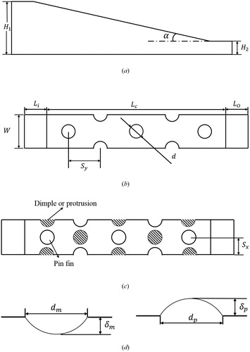
In this study, a wedge duct, shown in , with hemispherical dimples or protrusions mounted on the heated endwall surface is investigated by a numerical method. The details of the computational model are shown in . As shown in the figure, the extended length of the inlet segment and outlet segment are and
respectively. The converging segment of the channel is
in length. The width of the channel is
The streamwise distance between the two pin fins is
The dimples or protrusions are situated centrally between the pin fins with a spanwise distance
away from the pin fins. The diameter of the circular shaped pin fins is
The diameters of the hemispherical dimple and protrusion are
and
respectively. The investigated converging angles
are
and
The ratio between dimple depth
and dimple diameter
is
= 0.2 and the ratio between protrusion height
and protrusion diameter
is also
Figure 2. General schematics of the computational model.
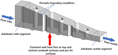
Figure 3. Detailed schematics of the computational model.
Six cases of the pin fin-dimple/protrusion wedge duct with different converging angles are investigated as shown in .
Table 1. Studied cases.
3. Computational details
3.1. Overview
Previous studies [Citation34, Citation35] provide the recommendations to choose the BSL turbulence model to calculate the steady-state, three-dimensional turbulent flow, and heat transfer. The calculations and solving of equation are performed by the commercial software ANSYS CFX [Citation36], which is widely used to solve and perform the governing equations of fluid flow and heat transfer by the finite volume method. The geometrical model and the computational mesh are generated by an in-house code based on MATLAB software [Citation22].
3.2. CFD validation
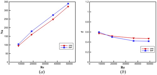
The experiments carried out by Rao et al. [Citation18] are referenced and the experimental results are introduced into this study. To verify the accuracy of the CFD results, computations corresponding to the experiments by Rao et al. [Citation18] were carried out. shows a comparison of computed and experimental results. It should be noted that the maximum deviations between the numerical results and the experimental results are for the Nusselt number and
for the friction factors, respectively. The CFD results show a favorable and decent match with the experimental results.
Figure 4. Comparison of the CFD results and the experimental results.
3.3. Boundary conditions
In this study, the inlet segment and the outlet segment are adiabatic. A constant surface heat flux of is applied on the endwall surface [Citation18] and the pin fin surfaces. The endwall surface and the pin fin surfaces are recognized as no-slip boundaries. The ideal gas air is employed as the fluid with a linear temperature-dependent thermal conductivity and viscosity. The temperature of the air flow at the inlet is
[Citation18] and the turbulence intensity is
To save computer resources, a pair of periodic boundary conditions is applied on the side wall surfaces spanwisely, which is shown in . To reduce the computational errors, high-resolution turbulence numerics and a high-resolution advection scheme are utilized in this study.
3.4. Governing equation
The governing equations of the heat transfer and fluid flow structure contain the conservation equation of mass, momentum, and energy. The equations are as follows [Citation36]:
The mass conservation:
(1)
(1)
The momentum conservation:
(2)
(2)
The energy conservation:
(3)
(3)
The turbulent kinetic energy equation and the dissipation rate
equation are:
(4)
(4)
(5)
(5)
where
(6)
(6)
(7)
(7)
(8)
(8)
(9)
(9)
(10)
(10)
(11)
(11)
(12)
(12)
(13)
(13)
(14)
(14)
(15)
(15)
The constants have the values:
3.5. Grid details and mesh independence
In this study, the geometrical model and the computational mesh are created by an in-house MATLAB code, and the quality of the computational mesh is above [Citation37]. The
values of the endwall surface are kept at approximately
The mesh details are shown in . To guarantee the numerical accuracy, a grid independence check has been conducted carefully with the number of grid elements ranging from
to
The grid independence results in show that the Nusselt numbers and friction factors are almost unchanged as the number of grid elements grows from
to
In order to save time and provide efficient use of the computer resources, the grid system with
grid elements is chosen for the final computations.
Figure 5. The mesh details.
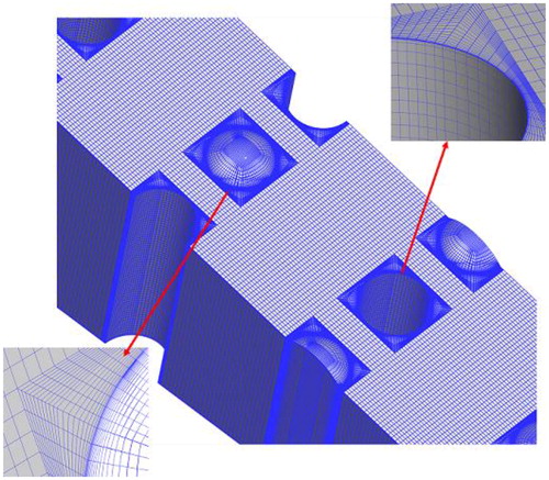
Table 2. Grid independence study.
3.6. Definition of parameters
For the airflow in the studied dimple-pin fin channels, Reynolds number is defined as:
(16)
(16)
where
is the density of the air inlet,
is the average velocity of the air inlet,
is the hydraulic diameter of the wedge duct inlet, and
is the dynamic viscosity of air at the inlet.
The heat transfer coefficient is defined as:
(17)
(17)
where
is the wall heat flux,
is the temperature of the endwall surface, and
is the temperature of air at the inlet.
The Nusselt number is defined as:
(18)
(18)
where
is the thermal conductivity of air.
The friction factor is defined as:
(19)
(19)
where
is the total pressure drop of the wedge duct.
The viscous dissipation function is defined as:
(20)
(20)
where
is the dynamic viscosity,
is the velocity component in x-direction,
is the velocity component in y-direction, and
is the velocity component in z-direction.
4. Results and discussion
4.1. Flow structure
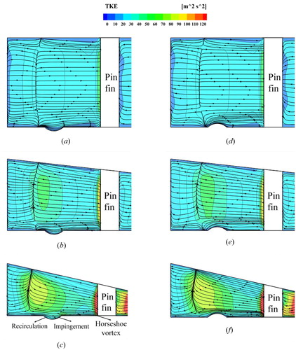
depicts a comparison of the streamline distributions and TKE distributions at the central longitudinal plane at Re = 30,000. A reversed pressure gradient and high TKE region emerge when the incoming airflow impinges on the leading edge of the pin fin. A horseshoe vortex, resulting from the fluid viscosity and reversed pressure gradient, is distributed at the bottom corner of the pin fin and has a significant effect on improving the local heat transfer [Citation4]. Further inspection of shows that cases with larger converging angle provide larger TKE at the leading edge of the pin fin. Concerning Baseline, Case 1 and Case 2, the Baseline has the smallest TKE in the mainstream and Case 1 shows the second largest TKE, while Case 2 shows the largest. The position where the highest TKE emerges in the mainstream depends on where the upstream flow merges [Citation20]. After passing through the pin fin, part of the airflow nearby the dimple separates and is involved in the flow recirculation at the front half of the dimple where a relatively lower TKE region is born, which will be discussed later. The remaining airflow shifts downwards by the flow recirculation and impinges on the rear half of the dimple [Citation38]. The impingement on the rear half of the dimple can make the boundary layer thinner and this is remarkably beneficial for the heat transfer augmentation. Eventually the impinging airflow is ejected out of the dimple from the rear rim of the dimple and reattaches on the endwall surface. Similarly, for cases with protrusions, Case 5 with a converging angle of shows the largest TKE in the mainstream. The incoming airflow impinges on the front surface of the hemispherical protrusion, and part of the airflow passes through the protrusion along the tangential direction of the protrusion surface.
Figure 6. Comparison of the streamline distributions and TKE distributions at the central longitudinal plane at Re = 30,000.
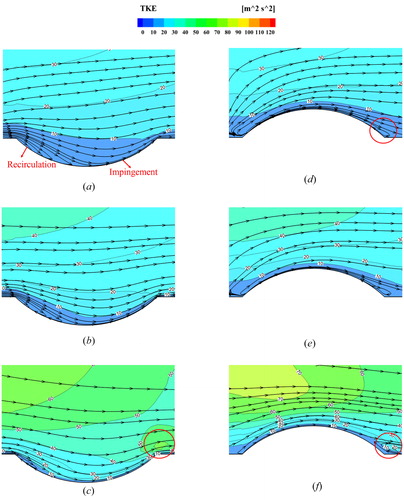
shows a comparison of the streamline distributions and TKE distributions near the dimple/protrusion at Re = 30,000. For the Baseline, Case 1, and Case 2, a low-speed recirculation region is found at the front half of the dimple which has negative effects on the local heat transfer. The impingement region at the rear half of the dimple is beneficial for heat transfer which was discussed above. It should be noted that cases with larger converging angle show smaller low-speed recirculation at the front half of the dimple and larger impingement region. Besides, the TKE in the vicinity of the dimple becomes larger with the increase of the converging angle. A very interesting phenomenon is that a collection of high TKE appears at the rear rim of the dimple in Case 2 due to the impingement and reattachment which does not exist in the Baseline and Case 1. For Case 3, Case 4, and Case 5, the airflow impinges on the front rim of the dimple and part of the airflow moves downstream along the tangential direction. For Case 3 and Case 4, the airflow separates at the rear half surface of the protrusion and then recirculates towards the upstream direction. Unlike these, the high-speed airflow in Case 5 flows across the protrusion and a recirculation region is formed by the streamline downstream. The separation or recirculation region behind the protrusion does have detrimental effects on the local heat transfer.
Figure 7. Comparison of the streamline distributions and TKE distributions near the dimple/protrusion at Re = 30,000.
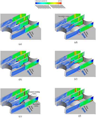
describes comparisons of the streamline distributions and vorticity distributions at spanwise planes perpendicular to the streamlines at Re = 30,000. A horseshoe vortex appears at the front of the pin fin which is in agreement with the discussion of . The difference is that cases with larger converging angle yield a stronger horseshoe vortex. For the Baseline, Case 1, and Case 2, a pair of counter-rotating vortices is formed inside the dimple cavity. The counter-rotating vortex pairs move downwards and are stretched into a pair of V-shaped vortex tubes [Citation39] which have a significant effect on improving the local heat transfer. It should be noted that the counter-rotating vortex pairs in Case 2 with a converging angle of are much stronger than in the other two cases. In addition, the included angle between the two vortex tubes becomes larger with the increase of the converging angle. Cases with protrusions are characterized with a pair of vortex tubes at the flat endwall surface downstream the protrusion. The vortex tubes originating from the rear part of the protrusion can make the boundary layer thinner and are favorable for heat transfer augmentation. Similarly, as the converging angle is increased, the vortex tubes move outside spanwisely and the included angle between the legs of the vortex tubes becomes larger. It should be noted that a pair of secondary vortices are induced above the vortex tubes mentioned above, and the secondary vortex pairs move closer to the endwall surface with increasing converging angle. Besides, a pair of counter-rotating vortices is distributed at the front of the protrusion. The special vortex pairs in Case 3 with a converging angle of
are much stronger than in the other two cases.
Figure 8. Comparison of the streamline distributions and vorticity distributions at spanwise planes perpendicular to the streamline at Re = 30,000.
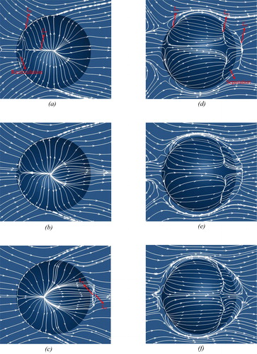
A comparison of the limiting streamline distributions at the endwall surface at Re = 30,000 is shown in . For the Baseline, Case 1, and Case 2, equipped with dimples on the endwall, a separation line () is observed at the front rim of the dimple which is a manifestation of the separated motion of the incoming airflow. In addition, a reattachment line (
) emerges at the central of the dimple, which is mainly induced by the counter-rotating motion of the vortices. Notice that in Case 2, after impinging on the rear part of the dimple, the airflow separates firstly and a separation line is observed at the flat endwall surface downstream the dimple. Then a reattachment line appears behind the separation line due to the reattachment motion of the airflow. Further inspection of shows that cases with larger converging angles show smaller recirculation regions at the front half of the dimple and larger impingement regions at the rear half of the dimple. Especially, the recirculation region in Case 2 has almost disappeared and is hard to distinguish. The phenomenon shows excellent match with the discussion of . Actually, wedge ducts with larger converging angle produce larger pressure gradients pointing from the top surface to the bottom endwall surface, which is responsible for the specific phenomenon. According to Luo et al. [Citation32], the increase of the flow impingement region at the rear half of the dimple and the reduction of the recirculation region at the front half of the dimple are favorable for enhancing the heat transfer. For Case 3, Case 4, and Case5, the incoming airflow impinges on the front surface of the protrusion and two reattachment lines emerge by the two sides of the protrusion symmetrically. Especially, a separation line appears at the flat endwall surfaces upstream the protrusion in Case 5. Due to the impingement and airflow accelerating motion above the protrusion, high wall shear appears at the protrusion surfaces according to Elyyan et al. [Citation40]. Part of the airflow moves downstream along the tangential direction of the protrusion surface after impingement. Furthermore, a separation line is observed at the back half of the protrusion when the shear layer encounters a reversed pressure gradient which is a manifestation of the separated motion of the shear layer. A large separation region is formed behind the protrusion due to the pressure gradient and the airflow above the protrusion with higher speed reattaches on the endwall surface. It is obvious that the separation region behind the protrusion in Case 5 is much larger than for the other two cases, while Case 3 with a converging angle of
has the smallest separation region. An additional feature is that part of airflow along the side edge of the protrusion is also entrained in the flow separation region behind the protrusion.
Figure 9. Comparison of the limiting streamline distributions at the endwall surface at Re = 30,000.
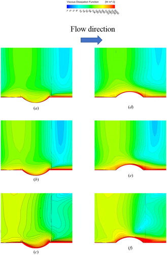
demonstrates a comparison of the viscous dissipation function of energy, in EquationEq. (20)
(20)
(20) , at the central streamwise plane at Re = 30,000. The viscous dissipation function is defined by the mechanical energy loss due to the fluid viscosity. The energy loss is transferred into heat energy irreversibly. For the Baseline, Case 1, and Case 2, high viscous dissipation function values are mainly concentrated at the front rim and rear rim of the dimple resulting from the flow recirculation, impingement, and reattachment. Case 2 with a converging angle of
shows the largest viscous dissipation function values, and Case 1 has the second largest. However, viscous dissipation function values in the Baseline are much smaller than for the other two cases. For Case 3, Case 4, and Case 5, the high viscous dissipation function values are mainly distributed at the front half of the protrusion caused by impingement, and also at the rear part of the protrusion due to the flow separation. Notice that Cases with larger converging angle show larger viscous dissipation function values due to higher speed and also larger separation region downstream the protrusion as shown in . An additional feature is that the viscous dissipation function in the mainstream above the dimples and protrusions is also increased distinctively with increasing wedge duct converging angle, which means larger energy loss.
Figure 10. Comparison of the viscous dissipation function on the central longitudinal plane at Re = 30,000.
4.2. Heat transfer enhancement
depicts a comparison of the local Nusselt number distributions at the endwall surface at Re = 30,000. For all the cases investigated, the region with relatively high Nusselt numbers appear at the front part of the pin fin which is caused by the airflow impingement and the horseshoe vortex. The high Nusselt number region at the front of the pin fin develops downstream and forms two strip-shape regions by the two sides of the pin fin. The strip-shape regions are mainly induced by the shedding of the horseshoe vortex generated at the front side of the pin fin and show a gradually decreasing trend for the Nusselt number. Besides, cases with larger converging angles show larger Nusselt numbers at the front of the pin fin and the strip-shape regions. For the Baseline, Case 1, and Case 2, there is also a high Nusselt number region at the back half of the dimple caused by the airflow impingement, and a high Nusselt number region at the flat endwall downstream the dimple created by the airflow reattachment and shedding of the counter-rotating vortex. The Nusselt numbers at the impingement region inside the dimple cavity and flat endwall surface downstream the dimple in Case 2 are much higher than those in the other two cases. A relatively low Nusselt numbers region is concentrated at the front half of the dimple and extends to the spanwise boundaries of the dimple due to the flow separation and recirculation. Notice that the low heat transfer region at the front half of the dimple becomes smaller in Case 1 and Case 2, which are characterized by larger wedge duct converging angle. The specific high Nusselt number distribution is in good accordance with the discussion of and .
Figure 11. Comparison of the Nusselt number distribution at the endwall surface at Re = 30,000.
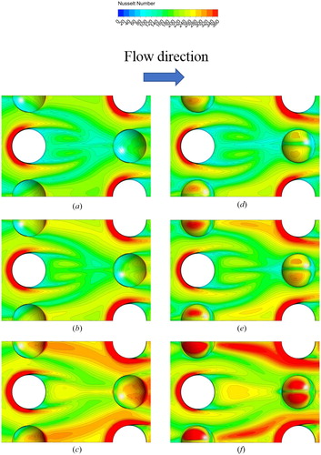
For Case 3, Case 4, and Case 5, due to the blocking effects of the protrusion, a low Nusselt number region appears at the leading corner between the endwall surface and the leading edge of the protrusion and it is shrank distinctively as the wedge duct converging angle is increased. It is also found that a pair of “pea-shape” regions with relative high Nusselt number appears on the protrusion surface which is mainly caused by the flow impingement. In addition, two strip-shape regions with high Nusselt number appear at the flat surface downstream the protrusion which is caused by the vortex tubes mentioned in . Case 5 with larger converging angle shows the highest Nusselt numbers both at the “pea-shape” region on the hemispherical protrusion and the strip-shape region downstream the protrusion. In addition, the flow separation region at the rear portion of the hemispherical protrusion is characterized by relatively low Nusselt numbers for all the three cases with protrusions mounted on the endwall surfaces. Summing up the above, Case 5 with the largest converging angle of has the best heat transfer augmentation compared with the other two cases with smaller converging angle.
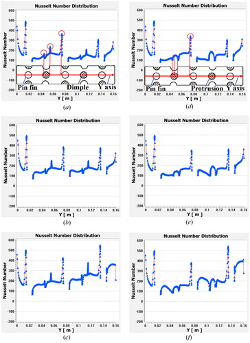
shows the Nusselt number variation along the streamwise centerline at the endwall surface at Re = 30,000. For cases with dimples, the Nusselt number distribution is characterized with a decreasing trend for the Baseline and Case 1 in general, while Case 2 with a converging angle of yields an increasing trend of the Nusselt number distribution. Besides, the Nusselt numbers in Case 2 are much larger than those in the other two cases. Generally, the Nusselt number behind the pin fin increases gradually and reaches a local large peak value upstream the dimple. A sharp drop is found at the front half of the dimple due to the low-speed recirculation, then the Nusselt number grows intensely and attains a larger local peak value at the rear rim of the dimple caused by the impingement, reattachment, and shedding of the vortex. Finally, the Nusselt number comes to the largest peak value at the front of the pin fin caused by the impingement. Similarly, Case 5 also shows a growing Nusselt number distribution in the whole wedge duct, which cannot be found in the other two cases with protrusions. With increasing converging angle, the overall Nusselt number is improved distinctively. The Nusselt number behind the pin fin increases gradually and then drops sharply to a local lowest peak value at the front of the protrusion due to the recirculation caused by protrusion blocking. The Nusselt number on the front half of the protrusion increases firstly and decreases again at the rear half of the protrusion due to the flow separation and recirculation, which is in good agreement with the phenomenon in . The largest Nusselt Number value also appears at the leading edge of the pin fin caused by impingement.
Figure 12. Comparison of the Nusselt number distributions along the streamwise centerline at the endwall surface at Re = 30,000.
displays the comparison of the normalized area-averaged Nusselt number for Re ranging from 10,000 to 50,000. The area-averaged Nusselt number values are determined by averaging the local Nusselt number on the endwall surface with a constant heat flux of The Nusselt number
used for normalization is given by Dittus–Boelter correlation [Citation41] for fully developed turbulent flow in a smooth circular channel:
(21)
(21)
Figure 13. Comparison of the normalized area-averaged Nusselt numbers for Re ranging from 10,000 to 50,000.
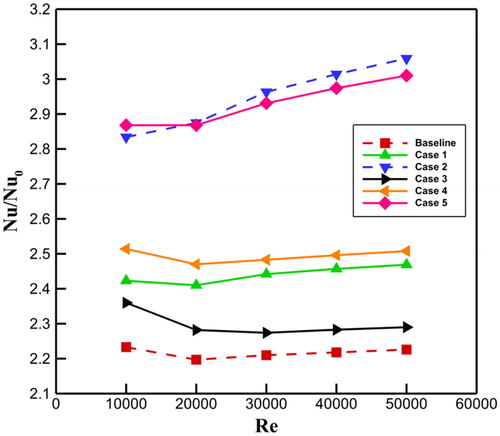
For the cases allocated with dimples on the endwall, Case 3 yields the best heat transfer enhancement with a sharp increase by for the normalized area-averaged Nusselt number compared to the Baseline. In addition, the normalized Nusselt number for Case 1 is increased by
in maximum compared to the Baseline. The normalized area-averaged Nusselt number for Case 5 with a converging angle of
shows the best heat transfer augmentation and is increased by
in maximum compared to the Baseline. Besides, the normalized area-averaged Nusselt number for Case 3 and Case 4 are increased by
and
compared to the Baseline, respectively.
4.3. Friction factor
The variation of the normalized friction factor of for Re ranging from 10,000 to 50,000 is shown in . The
used for the normalization of the friction factor is defined by the Blasius correlation [Citation41]:
(22)
(22)
Figure 14. Comparison of the normalized friction factors for Re ranging from 10,000 to 50,000.
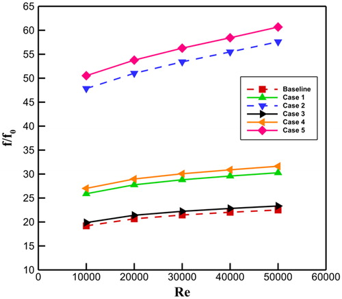
For all the three cases with dimples, the normalized friction factor increases with Re. Notice that the growth trend for Case 2, with a converging angle of is much sharper and steeper than for the other two cases. Specifically, Case 2 shows a huge increase by
for the normalized friction factor compared to the Baseline. The friction factor for Case 1 is increased by
compared with the Baseline. Case 3 and Case 4 show an increase by
and
for the normalized friction factors compared to the Baseline, respectively. Case 5 also has a steep increasing trend for the normalized friction factor as shown in the figure with a maximum increase by
compared to the Baseline.
4.4. Thermal performance
In order to evaluate the thermal performance properly, (area goodness factor) and
(volume goodness factor) are introduced for comparison for Re ranging from 10,000 to 50,000 as plotted in . It is obvious that both the area goodness factor and volume goodness factor decrease gradually with the increase of Re.
Figure 15. Comparison of the thermal performance of the whole wedge duct for Re ranging from 10,000 to 50,000.
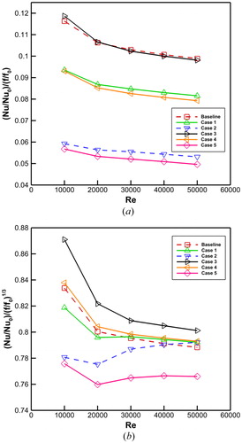
Notice that the converging angle has a significant reduction effects on the heat transfer enhancement performance. As obvious in , for cases with dimples, Case 1 and Case 2 show a remarkable decrease by and
respectively, in the area goodness factor compared to the Baseline. Case 3 shows a better heat transfer augmentation performance when Re < 20,000, with an increase by
compared to the Baseline. However, when Re > 20,000, the area goodness factors for Case 3 are smaller than those of the Baseline and are decreased by
in maximum. The area goodness factors for Case 4 and Case 5 are decreased by
and
respectively, compared to the Baseline.
For the volume goodness factor in , Case 1 shows smaller volume goodness factors with a maximum reduction by when Re < 30,000 and larger volume goodness factors with a maximum increase by
when Re > 30000 compared to the Baseline. The volume goodness factors for Case 2 are much smaller with a maximum decrease by
when Re < 40,000 and an increase by
when Re = 50,000. For cases with protrusions on the endwall surface, Case 3 yields the best heat transfer augmentation performance with a maximum improvement by about
for the volume goodness factor compared to the Baseline. Case 4 also shows a better heat transfer enhancement performance is associated with a maximum increase by
compared to the Baseline. However, Case 5 has the worst heat transfer performance and is accompanied with a distinctive reduction by
of the volume goodness factor compared to the Baseline.
5. Conclusions
In this study, a numerical method is utilized to investigate the flow structure and heat transfer characteristics of a pin fin-dimple/protrusion channel with different converging angle. The conclusions are as follows:
Pin fin-dimple wedge duct with larger converging angle produces better heat transfer enhancement due to flow acceleration, increase of impingement region and shrinkage of the flow recirculation region inside the dimple, but is also accompanied with a large friction factor.
Pin fin-protrusion wedge duct with larger converging angle are associated with a better heat transfer enhancement due to the flow acceleration and more intense impingement on the protrusion. It is also characterized with a large pressure drop penalty.
Considering the area goodness factor and volume goodness factor, the pin fin-protrusion wedge duct with a converging angle of
shows the best heat transfer performance. This wedge duct shows an increase by
| Nomenclature | ||
| d | = | pin fin diameter ( |
| = | dimple diameter ( | |
| = | protrusion diameter ( | |
| = | hydraulic diameter of the rectangular channel ( | |
| = | friction factor | |
| = | friction factor in smooth channel | |
| = | heat transfer coefficient ( | |
| = | wedge duct inlet height ( | |
| = | wedge duct outlet height ( | |
| k | = | turbulent kinetic energy (J) |
| L | = | total length (mm) of the wedge duct |
| = | length ( | |
| = | length (mm) of the wedge duct inlet segment | |
| = | length (mm) of the wedge duct outlet segment | |
| Nu | = | Nusselt number |
| = | Nusselt number in smooth channel | |
| = | Prandtl number | |
| = | inlet total pressure ( | |
| = | outlet total pressure ( | |
| = | wall heat flux ( | |
| = | Reynolds number | |
| = | distance between the dimple and pin fin in the spanwise direction ( | |
| = | distance between the pin fins in the streamwise direction ( | |
| = | inlet air temperature ( | |
| = | endwall surface temperature ( | |
| u | = | average velocity of the air inlet (m |
| = | velocity component in x-direction | |
| = | velocity component in y-direction | |
| = | velocity component in z-direction | |
| = | channel width ( | |
| = | wedge duct converging angle (°) | |
| = | dimple depth ( | |
| = | protrusion height (mm) | |
| = | thermal conductivity of air ( | |
| = | ynamic viscosity ( | |
| = | density of air ( | |
| = | viscous dissipation function | |
| = | dissipation rate | |
| CFD | = | computational flow dynamics |
| TKE | = | turbulent kinetic energy |
Additional information
Funding
References
- M. Montis, R. Ciorciari, S. Salvadori, M. Carnevate, and R. Niehuis, “Numerical prediction of cooling losses in a high-pressure gas turbine airfoil,” Proc. Inst. Mech. Eng., Part A: J. Power Energy, vol. 228, no. 8, pp. 903–923, 2014. DOI:10.1177/0957650914542630.
- W. Ba, X. Li, X. Ren, and C. Gu, “Aero-thermal coupled through-flow method for cooled turbines with new cooling model,” Proc. Inst. Mech. Eng., Part A: J. Power Energy, vol. 232, no. 3, pp. 254–265, 2018. DOI:10.1177/0957650917731629.
- J. C. Han, “Turbine blade cooling studies at Texas A&M University: 1980–2004,” J. Thermophys. Heat Transf., vol. 20, pp. 161–187, 2006. DOI:10.2514/1.15403.
- P. M. Ligrani, M. M. Oliveira, and T. Blaskovich, “Comparison of heat transfer augmentation techniques,” AIAA J, vol. 41, no. 3, pp. 337–362, 2003. DOI:10.2514/2.1964.
- D. E. Metzger, R. A. Berry, and J. P. Bronson, “Developing heat transfer in rectangular ducts with staggered arrays of short pin fins,” J. Heat Transf., vol. 104, no. 4, pp. 700–706, 1982. DOI:10.1115/1.3245188.
- D. E. Metzger, Z. X. Fan, and W. B. Shepard, “Pressure loss and heat transfer through multiple rows of short pin fins”, presented at Proceedings of the Seventh International Conference, vol. 3, A83-42700 20–34, Munich, West Germany, Sep. 6–10, 1982.
- Z. Chen, Q. Li, D. Meier, and H. J. Warnecke, “Convective heat transfer and pressure loss in rectangular ducts with drop-shaped pin fins,” Heat Mass Transf., vol. 33, no. 3, pp. 219–224, 1997. DOI:10.1007/s002310050181.
- I. K. Choi, T. Kim, S. J. Song, and T. J. Lu, “Endwall heat transfer and fluid flow around an inclined short cylinder,” Int. J. Heat Mass Transf., vol. 50, no. 5–6, pp. 919–930, 2007. DOI:10.1016/j.ijheatmasstransfer.2006.08.012.
- M. K. Chyu, C. H. Yen, and S. C. Siw, “Comparison of heat transfer from staggered pin fin arrays with circular, cubic and diamond shaped elements”, ASME Paper No. GT2007-28306, 2007.
- F. Zhou, and I. Catton, “Numerical evaluation of flow and heat transfer in plate-pin fin heat sinks with various pin cross sections,” Numer. Heat Transf., Part A, vol. 60, no. 2, pp. 107–128, 2011. DOI:10.1080/10407782.2011.588574.
- S. C. Siw, M. K. Chyu, and M. A. Alvin, “Heat transfer enhancement of internal cooling passage with triangular and semi-circular shaped pin-fin array”, ASME Paper No. GT2012-69266, 2012.
- P. M. Ligrani, J. L. Harrison, G. I. Mahmood, and M. L. Hill, “Flow structure due to dimple depression on a channel surface,” Phys. Fluids, vol. 13, no. 11, pp. 3442–3451, 2001. DOI:10.1063/1.1404139.
- N. K. Burgess, and P. M. Ligrani, “Effects of dimple depth on channel Nusselt Numbers and friction factors,” J. Heat Transf., vol. 127, no. 8, pp. 839–847, 2005. DOI:10.1115/1.1994880.
- J. Park, and P. M. Ligrani, “Numerical predictions of heat transfer and fluid flow characteristics for seven different dimpled surfaces in a channel,” Numer. Heat Transf., Part A, vol. 47, no. 3, pp. 209–232, 2005. DOI:10.1080/10407780590886304.
- Y. Rao, Y. Feng, B. Li, and B. Weigand, “Experimental and numerical study of heat transfer and flow friction in channels with dimples of different shapes,” ASME J. Heat Transf., vol. 137, no. 3, pp. 031901, 2015.
- L. Ye, X. Yang, B. Sundén, and Z. Feng, “Effect of droplet characteristics on heat transfer of mist/air cooling in a pin-finned channel,” Numer. Heat Transf., Part A, vol. 75, no. 5, pp. 291–308, 2019. DOI:10.1080/10407782.2019.1586426.
- D. Zhang, Q. Jing, Y. Xie, and Z. Shen, “Numerical prediction on turbine blade internal tip cooling with pin-fin and dimple/protrusion structures,” Numer. Heat Transf., Part A, vol. 70, no. 9, pp. 1021–1040, 2016. DOI:10.1080/10407782.2016.1214515.
- Y. Rao, C. Wang, and Y. Xu, “An experimental study of pressure loss and heat transfer in the pin fin-dimple channels with various dimple depths,” Int. J. Heat Mass Transf., vol. 55, no. 23–24, pp. 6723–6733, 2012. DOI:10.1016/j.ijheatmasstransfer.2012.06.081.
- Y. Rao, Y. Xu, and C. Wang, “An experimental and numerical study of flow and heat transfer in channels with pin fin-dimple and pin fin arrays,” Exp. Therm. Fluid Sci., vol. 38, pp. 237–247, 2012. DOI:10.1016/j.expthermflusci.2011.12.012.
- Y. Rao, Y. Xu, and C. Wang, “A numerical study of the flow and heat transfer in the pin fin-dimple channels with various dimple depths,” J. Heat Transf., vol. 134, no. 7, pp. 071902, 2012. DOI:10.1115/1.4006098.
- L. Luo, C. Wang, L. Wang, B. Sundén, and S. Wang, “Heat transfer and friction factor performance in a pin fin wedge duct with different dimple arrangements,” Numer. Heat Transf., Part A, vol. 69, no. 2, pp. 209–226, 2016. DOI:10.1080/10407782.2015.1052301.
- L. Luo, C. Wang, L. Wang, B. Sundén, and S. Wang, “Heat transfer and friction factor in a dimple-pin fin wedge duct with various dimple depth and converging angle,” Int. J. Numer. Methods Heat Fluid Flow, vol. 26, no. 6, pp. 1954–1974, 2016. DOI:10.1108/HFF-02-2015-0043.
- L. Luo, W. Du, S. Wang, B. Sundén, and X. Zhao, “Flow structure and heat transfer characteristics of a 90°-turned pin-finned wedge duct with dimples at different locations,” Numer. Heat Transf., Part A, vol. 74, pp. 143–162, 2018. DOI:10.1080/10407782.2017.1421373.
- L. Luo et al., “Convergence angle and dimple shape effects on the heat transfer characteristics in a rotating dimple-pin fin wedge duct,” Numer. Heat Transf., Part A, vol. 74, no. 10, pp. 1611–1635, 2018. DOI:10.1080/10407782.2018.1543920.
- M. E. Kithcart, and D. E. Klett, “Heat transfer and skin friction comparison of dimpled versus protrusion roughness,” J. Enhanced Heat Transf., vol. 3, no. 4, pp. 273–280, 1996. DOI:10.1615/JEnhHeatTransf.v3.i4.30.
- S. D. Hwang, H. Kwon, and H. H. Cho, “Heat transfer with dimple/protrusion arrays in a rectangular duct with a low Reynolds number range,” Int. J. Heat Fluid Flow, vol. 29, no. 4, pp. 916–926, 2008. DOI:10.1016/j.ijheatfluidflow.2008.01.004.
- J. E. Kim, J. H. Doo, M. Y. Ha, H. S. Yoon, and C. Son, “Numerical study on characteristic of flow and heat transfer in a cooling passage with protrusion-in-dimple surface,” Int. J. Heat Mass Transf., vol. 55, no. 23-24, pp. 7257–7267, 2012. DOI:10.1016/j.ijheatmasstransfer.2012.07.052.
- G. Xie, J. Liu, P. M. Ligrani, and W. Zhang, “Numerical analysis of flow structure and heat transfer characteristics in square channels with different internal-protruded dimple geometrics,” Int. J. Heat Mass Transf., vol. 67, pp. 81–91, 2013. DOI:10.1016/j.ijheatmasstransfer.2013.07.094.
- Y. Xie, H. Qu, and D. Zhang, “Numerical investigation of flow and heat transfer in rectangular channel with teardrop dimple/protrusion,” Int. J. Heat Mass Transf., vol. 84, pp. 486–496, 2015. DOI:10.1016/j.ijheatmasstransfer.2015.01.055.
- S. D. Hwang, H. G. Kwon, and H. H. Cho, “Local heat transfer and thermal performance on periodically dimple-protrusion patterned wall for compact heat exchanger,” Energy, vol. 35, no. 12, pp. 5357–5364, 2010. DOI:10.1016/j.energy.2010.07.022.
- J. Lan, Y. Xie, and D. Zhang, “Heat transfer enhancement in a rectangular channel with the combination of ribs, dimples and protrusions”, ASME Paper No. GT2011-46031, 2011.
- L. Luo, W. Du, F. Wen, S. Wang, and Z. Zhao, “Convergence angles effect on heat transfer characteristics in a wedged duct with dimples/protrusions,” Heat Transf. Res., vol. 48, no. 14, pp. 1237–1262, 2017. DOI:10.1615/HeatTransRes.2017017578.
- L. Luo, D. Qiu, W. Du, B. Sundén, Z. Wang, and X. Zhang, “Surface temperature reduction by using dimples/protrusions in a realistic turbine blade trailing edge,” Numer. Heat Transf., Part A, vol. 74, no. 5, pp. 1265–1283, 2018. DOI:10.1080/10407782.2018.1515333.
- L. Luo, H. Yan, W. Du, S. Wang, C. Li, and X. Zhang, “Flow structure and heat transfer characteristics of a rectangular channel with pin fins and dimples with different shapes,” ASME J. Thermal Sci. Eng. Appl., vol. 11, no. 2, pp. 024501, 2018.vol DOI:10.1115/1.4041598.
- L. Luo, W. Du, S. Wang, W. Wu, and X. Zhang, “Multi-objective optimization of the dimple/protrusion channel with pin fins for heat transfer enhancement,” Int. J. Numer. Methods Heat Fluid Flow, vol. 29, no. 2, pp. 790–813, 2019. DOI:10.1108/HFF-05-2018-0194.
- ANSYS CFX, Reference Guide, Release 15, 2013.
- ANSYS ICEM CFD, Reference Guide, Release 15, 2013.
- W. Zhou, Y. Rao, and H. Hu, “An experimental investigation on the characteristics of turbulent boundary layer flows over a dimpled surface,” ASME J. Fluid Eng., vol. 138, no. 2, pp. 021204, 2016.
- S. Wang, W. Du, L. Luo, D. Qiu, X. Zhang, and S. Li, “Flow structure and heat transfer characteristic of a dimpled wedge channel with a bleed hole in dimple at different orientations and location,” Int. J. Heat Mass Transf., vol. 117, pp. 1216–1230, 2018. DOI:10.1016/j.ijheatmasstransfer.2017.10.087.
- M. A. Elyyan, and D. K. Tafti, “Effect of Coriolis forces in a rotating channel with dimples and protrusions,” Int. J. Heat Fluid Flow, vol. 31, no. 1, pp. 1–18, 2010. DOI:10.1016/j.ijheatfluidflow.2009.10.002.
- B. Sundén, Introduction to Heat Transfer. Southampton, UK: WIT Press, 2012.