
 ?Mathematical formulae have been encoded as MathML and are displayed in this HTML version using MathJax in order to improve their display. Uncheck the box to turn MathJax off. This feature requires Javascript. Click on a formula to zoom.
Abstract
This study conducts an investigation and feasibility study on different Reynolds numbers (6000–12000) and Rotation numbers (0.05–0.25) in a matrix cooling geometry. An intended geometry that can be used in gas turbine blades is provided based on flow and heat transfer performance given in these Reynolds and rotation number ranges for stationary and rotational state and then compared with experimental data. In this work, a 3D simulation method for each states (stationary and rotation) has been used for two layers matrix cooling with four inlets in each layer in a straight rectangular channel. The results indicate that among the common methods used in the trailing edge of a gas turbine blade, the matrix cooling method has heat transfer in stationary and rotary states ∼2–3 times higher than those of a smooth channel. Also results showed that rotation significantly affects heat transfer characteristics. Heat transfer increases in the pressure-side by a factor of 3 (at a Rotation number of 0.15 and Reynolds number 6000) which is an important property of rotation. According to the specific rotation direction chosen in this study, in comparison with previous studies, the pressure side and suction side location in stationary and rotation states are different and this results in lower decrease of heat transfer in the suction side for the rotation state. It is observed that using this structure increases the thermal performance about 30% by changing the flow behavior between stationary and rotary states.
1. Introduction
Gas turbines can be considered to be the greatest moving engines which produce large amount of energy based on size and weight. Increase of inlet gas temperature, which is the result of the designed gas turbines for high thermal efficiency and net power, has necessitated the need for cooling of the hot parts of turbines (blades, nozzles, and disks). Matrix cooling, which is also known as lattice or vortex cooling is a new method for internal cooling. In matrix cooling, heat transfer is tremendously increased due to increase of heat transfer surface, flow impingement, and also flow turning which leads to turbulent flow.
A matrix cooling geometry is composed of two layers of longitudinal ribs at an opposite angle that forming a system of crossing sub-channels. In the rotational state, according to the direction of rotation, the two layers are representing the suction side as the leading surface and the pressure side as the trailing surface, respectively. The fluid that passes the sub-channels, turns at the dead end of the side wall and moves into the sub-channel on the opposite layer with some mixing with the fluid from the other sub-channels. The flow should turn by the angle 2b (b is angle of sub-channels inclination) switching from one sub-channel to another sub-channel in the opposite layer or vice versa. These flow movements make a swirl motion and the interaction with the cross flow increased the turbulence of the flow. This also increases the heat transfer coefficient. Moreover, according to the significant increase of surface area, the heat transfer is also more increased. The longitudinal ribs in this structure have several benefits, such as improvement in structural strength, heat transfer and uniform heat transfer distribution along sub-channels both axially and laterally.
Internal cooling with the effects of turbulator geometries and rotation of the flow field and heat transfer has been studied extensively. Han et al. [Citation1] experimentally investigated the effects of four rib orientations with different configuration on heat transfer in internal cooling of gas turbine blades. Their studies showed strong effects of rib geometries on flow pattern and heat transfer distribution. Laschet et al. [Citation2] predicted the aerothermal behavior of a transpiration cooled plate, a multiscale approach based on the homogenization method. By use of the 3D conjugate flow and heat transfer analysis, they extracted the stationary state data and transferred them to the microscale unit cell discretized by finite elements. The effect of the different cooling designs on the effective conductivities was discussed. Finally, they investigated the influence of the selection of the unit cell position on these effective thermal properties.
Chandra et al. [Citation3] studied heat transfer and friction characteristics of a fully developed turbulent air flow in a square channel with transverse ribs on one, two, three, and four walls. They concluded that, the four ribbed walls case showed a high increase in heat transfer compared to other ribbed walls cases. They showed that, heat transfer performance decreased with increasing Reynolds number and with each additional ribbed wall. Won et al. [Citation4] experimentally investigated local flow structure and surface Nusselt numbers for a stationary channel with an aspect ratio of 4 and angled rib turbulators inclined at 45° with perpendicular orientations on two opposite surfaces. Their results showed that the increases in the three dimensional turbulence transport, as well as other flow phenomena, are related to the local Nusselt numbers, which vary significantly over the surface of the ribbed channel. Bunker [Citation5] gave detailed information concerning the heat transfer coefficients and pressures in static latticework (vortex) cooling channels. He found heat transfer coefficient enhancement levels in the range of 2.5–3. He showed that latticework channels have significant potential and should be further investigated. Acharya et al. [Citation6] presented the first experimentally study on heat transfer and pressure drop in a matrix cooling structure under conditions of rotation. In their study, a latticework coolant passage, with orthogonal-ribs, was studied in a rotating heat transfer test-rig for a range of Reynolds numbers (Re), Rotation numbers (Ro), and density ratios. They indicated that a latticework cooling geometry can provide comparable heat transfer enhancements and thermal performance factors as conventional rib-turbulators, with potential benefits of stream-wise uniformity in the heat transfer coefficients and added blade strength. They extended the study in 2005 [Citation7]. Saha et al. [Citation8] reported the heat transfer distribution and pressure drop through a converging lattice-matrix structure. This structure represents a gas turbine blade trailing-edge cooling passage. They found higher thermal performance than for pin fins which are widely used in gas turbine blades. For pin fins the thermal performance factor is in the range of 0.7–0.85 based on different orientations of the pin fin. Siddappa et al. [Citation9] performed 3 D numerical simulations of matrix cooling configurations having two and three layered rectangular sub-channels. The Nusselt number, friction factor and overall thermal performance were evaluated and compared with a smooth channel. They showed enhancement in heat transfer of matrix configuration and reported that it is due to increased heat transfer area, impinging and swirling flow in the sub-channels. The Nusselt number ratios (Nu/Nu0) for the whole matrix structure under stationary conditions were approximately 4–5 times higher than those of a smooth channel. Carcasci et al. [Citation10] reported in comparison to conventional turbulated serpentines or pin–fin geometries, that a lattice–matrix structure can potentially provide higher heat transfer enhancement levels with similar overall pressure losses. This experimental investigation provided heat transfer distribution and pressure drop of four different lattice–matrix geometries with crossing angle of 45 deg between ribs. Measurements showed that the heat transfer enhancement level Nus/Nu0 decreased with Reynolds number but was always higher than 2. Their results have been compared with previous literature data on similar geometries and showed good agreement. Rao et al. [Citation11] experimentally and computationally investigated heat transfer and flow field in a latticework cooling channel with U-shaped sub-channels combined with dimple vortex generators over the Reynolds number range of 7700–36,985. The comparison between the experimental and numerical data showed that the numerical computation model can reasonably well predict the heat transfer and pressure loss in the latticework cooling channels. They indicated that the superior heat transfer enhancement capability of the latticework cooling is mainly due to the remarkably increased heat transfer area, turning effects producing strong vertical flow in the sub-channels, and the interactions between the flows in the crossing sub-channels, as well as the interactions between the flow and the crossing ribs on the opposite side. Oh et al. [Citation12] gave detailed local heat/mass transfer and pressure drop characteristics in a matrix cooling channel, under rotating conditions. In the stationary case, the heat transfer characteristics were dominated by turning, impinging, and swirling flow, induced by the matrix channel geometry. In the rotating cases, the effect of rotation on heat/mass transfer characteristics differed from that of typical rotating channels with radially outward flow. They showed that as the rotation number increased, the Sherwood number ratios increased on the leading surfaces but changed only slightly on the trailing surfaces. The thermal performance factors increased with rotation number due to the increased Sherwood number ratios and decreased friction factor ratios. Saha et al. [Citation13] presented detailed heat transfer coefficients and pressure drops through two different lattice structures suitable for use in the trailing edge of a gas turbine airfoil. Two lattice structures were studied experimentally with one lattice structure having four-entry channels and the second lattice structure having two entry channels. The results showed that the two-inlet-channel lattice structure produced higher values of the heat transfer coefficient and lower values of the pressure drop. The data from the converging lattice structures were compared with the published pin fin data, which is the common standard for trailing edge applications. Comparable or higher thermal performance and added structural rigidity can make the lattice structure a suitable alternative of pin fins in trailing edge applications. Carcasci et al. [Citation14] used experimental tests to present the combined effects of rotation and channel orientation on heat transfer and pressure drop along two scaled-up matrix geometries suitable for trailing edge cooling of gas turbine airfoils. Rotation enhancement on heat transfer is substantially insensitive to the variation of model inclination from 0° to 30° with respect to the rotating plane. From this study, it was found that in view of a future application within a trailing edge system these results can be considered promising because they are higher than other conventional cooling schemes such as pin fins. Tian et al. [Citation15] investigated fluid flow and heat transfer over a three-dimensional staggered circular pin-finned tube numerically. Effects of six geometric parameters and pin-fin arrangement in the flow direction on the thermo-hydraulic performance were investigated in details by adopting the performance evaluation plot of enhanced heat transfer oriented for energy-saving. The results showed that the pin-fin diameter, pin-fin length, and pin-fin number around the tube have positive effects on improving thermo-hydraulic performance, but the transverse tube pitch and the fin axial pitch have negative effects on improving thermo-hydraulic performance.
Zhou et al. [Citation16] studied the flow and heat transfer mechanisms of mist/air film cooling with three hole types under three blowing ratios. Mist/air cooling performances of cylindrical hole, fan-shaped hole, and console hole were studied numerically. The results showed that mists enhancement on cooling effectiveness is significantly impaired at a higher blowing ratio in cylindrical hole and fan-shaped hole cases. They found that the cooling effectiveness can maintain a relatively high value at each blowing ratio in console hole cases.
1.1. Objectives of this study
In this work, numerical computations for 3D turbulent flows over a two layered matrix configuration of a rectangular duct are conducted in static and rotational states with the main aim of examining the changes in the flow structure and heat transfer characteristics. The first objective of the present study is to document the effects of rotation and stationary state on the heat transfer and compare these in a matrix channel. To reach this goal, a specific direction of rotation has been considered and variations of heat transfer of stationary and rotational matrix cases are developed and presented in diagrams. Another objective of this study is to find the heat transfer performance of matrix cooling geometries for a range of Reynolds numbers and rotation numbers.
2. Computational analysis
2.1. Description of physical models
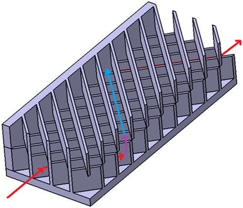
In order to understand the physical aspects of the heat transfer characteristics in a matrix cooling geometry, three-dimensional and steady-state numerical computations were carried out for a rectangular matrix channel in static and rotational states. shows a schematic of a matrix configuration with one flow direction.
Figure 1. Matrix geometry and one flow path.
The matrix configuration has two layered rectangular sub-channels and the rib angle is taken as 45°. The air inflow has Reynolds numbers between 6000 and 12000 and the rotation number varies between 0 and 0.25. A summary of the cases studied is given in .
Table 1. Summary of studied cases.
In this geometry, the fluid enters simultaneously from four sub-channels in the top and bottom of the matrix channel. The fluid in each sub-channel moves to the sub-channel on the other surface after crossing the lattice. Thus, each sub-channel has an impingement region in the inlet and a turning region in the outlet. In the rotation state, choosing this direction of rotation enables better heat transfer increase compared with a previous study [Citation6]. This is one of the important choices that was evaluated at the simulation testing stages. Hence, by the impingement, turning, mixing and increasing the turbulence of the flow through the sub-channels, the heat transfer will be increased.
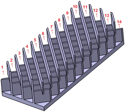
Each sub-channel in the two layered structure has specified distributions of the flow. So, showing changes in each sub-channel will be useful. The sub-channel numbering of the computational domain for the top layered channel are indicated in . For the bottom layered channel, this pattern is the same but with opposite angle.
Figure 2. Sub-channel numbering for the top-layered channel of the matrix geometry.
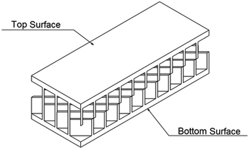
Two of the four side walls, in stationary and rotation case of the matrix cooling channel are denoted as top surface and bottom surface. For these two cases, top and bottom surfaces of two opposite layers are shown in .
Figure 3. Top and bottom surfaces in stationary and rotation cases.
The rotation axis origin is set 150 mm from the inlet and the rotation axis direction is horizontal. The rotation axis and direction of rotation are shown in .
Figure 4. Details of rotational case about (a) the rotation axis and direction of rotation and (b) leading and trailing surfaces.
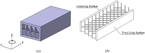
According to the tendency of the flow in this rotational state, the back and front surfaces of the rectangular case are considered as leading (suction side) and trailing (pressure side) surface, respectively, as shown in . This selection is done according to the direction of rotation that is selected in this study and the flow tendency when this case is rotating.
For eliminating the effects of reverse flow in the outlet, an extended region of 50 mm length has been used. The dimensions of the cross section are W = 52 mm and H = 30 mm. The length of the overall channel is L = 180 mm. The test model configuration under investigation has the following characteristics: the channel has 13 rows of ribs in each layer with square cross section. This case has 14 sub-channelled in each layer. = 0.63 and
= 0.03. The main geometric parameters for the case are summarized in and are depicted in .
Figure 5. Geometrical dimensions in different views of matrix geometry.
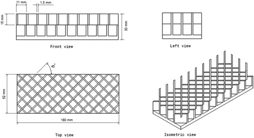
Table 2. Dimension of test geometry.
Leading and trailing surfaces of the channel are heated uniformly from the back sides of the test section, whereas the other side walls of the channel are insulated. The surfaces are treated as no-slip boundaries. A uniform velocity and temperature boundary conditions are set at the velocity inlet and a pressure outlet condition is selected at the outlet. The fluid is assumed to be incompressible with constant thermal physical properties [Citation17]. The flow is assumed to be three-dimensional, turbulent, steady and rotational. The working fluid is dry air.
For this computational study, the incompressible steady-state Reynolds-averaged Navier–Stokes equations) RANS (with a second order volume discretization scheme were solved. The employed turbulence model was the low Reynolds number k-ε RNG turbulence model combined with enhanced wall treatment [Citation18]. For the rotational case, the low Reynolds number k-ω SST turbulence model [Citation19] were used. A turbulence intensity of 4% and a hydraulic diameter of 38.05 mm are used to compute the turbulence quantities at the inlet.
For the RANS model, because a low Reynolds number formulation is used, it is important that the value of the closest grid points to the wall is of the order of unity. In this work, for all computations, the
values for the first layer height are 0.5–1 for all Reynolds numbers investigated. The SIMPLEC algorithm couples pressure and velocity [Citation18].
2.2. Validation
The numerical results are compared to experimental data and they are in reasonably good agreement with the experimental results. Verification of the heat transfer and friction factor of the stationary matrix cooling in a rectangular channel is performed by comparing with the previous values under similar boundary conditions in the Reynolds number range of 6000–12000 as shown in . The choice and validation of the turbulence model was carried out by matching the conditions considered by previous numerical studies [Citation12].
Figure 6. Nusselt number ratio comparison with Carcasci [Citation10] and Saha [Citation13] for different Reynolds number.
![Figure 6. Nusselt number ratio comparison with Carcasci [Citation10] and Saha [Citation13] for different Reynolds number.](/cms/asset/e2f94738-7514-49ba-a3dc-74278a53f06c/unht_a_1630236_f0006_b.jpg)
The present numerical simulation results for stationary state are found to be in excellent agreement with experimental values obtained from Carcasci et al. [Citation10] for the Nusselt number, with less than 5.1% maximum deviations. Validation for the normalized friction factor for stationary state was performed by comparing with the experimental data obtained by Carcasci et al. [Citation10] in the Reynolds number range of 5000–11000, as shown in .
Figure 7. Friction factor ratio for different Reynolds number.
These results provide a strong confidence in further investigation of the channel flow in the rotating matrix channel case.
3. Results and discussion
3.1. Procedure and data reduction
Because these investigations examined how the thermal development through this cooling passage is affected by several factors like rotation, this section has been divided into two sub sections. First, by considering the flow field computations in the stationary case, the results from the numerical simulations are concluded and compared. Then in the second part, by considering the rotational state, the effect of the rotational parameters has been concluded and also the difference between these two situations have been revealed.
In this study, to calculate the average Nusselt number for the channel and minimize the error, boundary conditions are entered individually between each ribs and the heat transfer coefficient is obtained for each of them. This method is used to enable usage of the pattern from the experimental case [Citation20]. In the experimental case, to obtain temperature distribution, a special method has been chosen for all walls. First, liquid crystal thermography (LCT) has been used for ribbed walls. Then a charge-coupled device (CCD) is used to take pictures from these walls and to observe the temperature distributions. With the data from this method the local Nusselt number is obtained for each cell. The local temperature in center of each cell has been extracted to calculate for each ribbed walls. The mass weighted average method has been used to calculate the bulk temperature (
) from the fluid volume above each walls. Then for each cell, the heat transfer coefficient and the Nusselt number were obtained. EquationEquation (5)
(5)
(5) below has been used to calculate the average Nusselt number in each area.
For the fluid volume, heat transfer analysis for steady state has been done for different Reynolds numbers. According to converged values of the intended geometry, the Nusselt number for each cell is defined by:
(1)
(1)
For the Reynolds number effect, concerning both experimental and computational results, the Nusselt number has been normalized with the Dittus–Boelter/McAdams correlation value at the same Reynolds and Prandtl numbers. For this range of Reynolds numbers, the correlation is given by [Citation21]:
(2)
(2)
The heat transfer coefficient (h) and then Nusselt number ratio are calculated as follows:
(3)
(3)
(4)
(4)
Where is the wall temperature,
is the bulk temperature at the x location. Finally, to compare numerical results with experimental results, the below formula is used to calculate the total Nusselt number for the walls of all cells:
(5)
(5)
N is the number of cells in the intended area. This formula is the same for static and rotational states.
To calculate the friction factor of the flow across the matrix cooling channel and to normalize it (Karmen–Nikuradse equation) the below formulas have been used [Citation22]:
(6)
(6)
(7)
(7)
In the above equations, ΔP is the pressure drop along the flow path, is the distance between two positions in calculation of pressure and ρ is the air density.
The thermal performance to describe the overall cooling efficiency is obtained from the heat transfer enhancement and friction loss increment as below [Citation23]:
(8)
(8)
3.2. Stationary channel
In general, the employed low Reynolds number k − ε turbulence model for the stationary case predicts reasonable agreement with the experimental data when one employs a suitable grid, heat flux and proper boundary conditions.
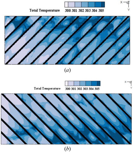
shows the temperature contours in the top and bottom surfaces at Re = 12000 for the stationary condition. In this figure also the sub-channels numbering and the impingement and turning regions of them have been specified. As is obvious, the heat transfer distributions on the two surfaces are almost similar.
Figure 8. Temperature distribution for (a) top surface and (b) bottom surface of matrix geometry in stationary state.
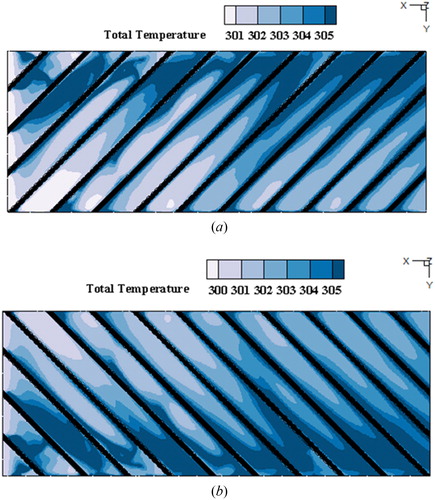
The impingement and turning regions in the two surfaces stay opposite to each other. As seen in this figure, on both surfaces 6–10 sub-channels have the most high heat transfer that leads to larger temperature drop according to increased turbulent mixing. In each sub-channel, the temperature increased gradually in the streamwise direction. Furthermore, in each sub-channel when the flow turns to another sub-channel, the boundary layer development is interrupted along each sub-channel and this leads to enhanced heat transfer coefficients. Also the impingement region in each surface has higher heat transfer and almost 50% higher than those in the turning region. The temperature after the impingement region slowly increases due to development of thermal boundary layer. The flow in each sub-channel produces a swirling flow and shear force in opposite sub-channel that lead to postponed increase of the thermal boundary layer. All in all, the contours showed that an almost uniform temperature distribution appears in the matrix structures for the stationary state [Citation11].
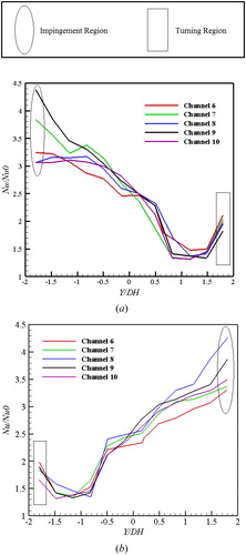
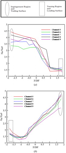
shows the stream-wise distributions in the middle region of the 6th to 10th sub-channels at Re = 12000 for stationary condition. A feature of the matrix geometry is that it maintains the overall and uniform heat transfer coefficient high in both axial directions of the geometry. As observed by Siddappa et al. [Citation9], the Nusselt number ratios along the 7th to 11th channels for the top surface are decreased and for the bottom surface are increased. Also in this study, the Nusselt number ratios in the top surface decreased as
increased and for the bottom surface the Nusselt number ratio increased as
increased. The Nusselt number ratio at the entrance of each channel for the top surface and the end of each channel in the bottom surface was very high due to the impinging effect of the turning flow from the opposite surface. Also at the end of each channel for the top surface and the entrance of each channel for the bottom surface, the Nusselt number ratio increased slightly due to the turning region where a counter-rotating vortex near the corner of the turning flow is formed. For Re = 12000,
values in the impingement region were in the range of 3–4.5, while
values in the turning region were in the range of 1.6–2.2. By comparing figures a and b, a little bit higher value of the heat transfer ratio is observed for the top surface for each sub channel. One can see then, that this distribution of the heat transfer is a particular feature of this structure.
Figure 9. Variation of Nu number ratio as function of dimensionless width in each sub-channel for (a) top surface and (b) bottom surface of matrix geometry in stationary state.
shows the Nu number ratio variation in the stream-wise direction at the mid-way point of the channel as a function of Reynolds number for the stationary state. The Nusselt number ratio value increased at the low Reynolds number to a maximum value at Re = 10000, but then it decreased for increasing Reynolds number. The higher values along the top and bottom sides are associated with the impinging flow into the sub-channels from the opposite walls at these locations. The same behavior was observed in the rotational states.
Figure 10. Nusselt number ratio for different Reynolds numbers in static case.
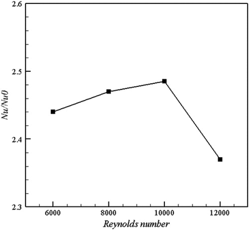
It can be seen that the enhancement level of the Nusselt number relative to the smooth channel is in the range of 2–2.5 and this is a significant advantage of the matrix configuration. Also, verification of the heat transfer for the static case of the matrix cooling is first performed by a comparison with the values from previous experimental results under a similar operating condition as shown in .
The present numerical static matrix channel results are found to be in good agreement with experimental results obtained from Saha et al. [Citation13] and Carcasci et al. [Citation10] for the Nusselt number within 4–11% maximum deviation.
Almost at all Reynolds numbers in Carcasci’s results, the values of the Nusselt number ratio are about 8% higher than the values of the Saha’s results. However, the numerical results slightly over-predict the heat transfer, which might be due to over-prediction of the turbulent Reynolds stresses. In general, the present simulations are in decent good agreement with the experiments. Therefore, the numerical solution procedure is employed in the study of rotation matrix cooling.
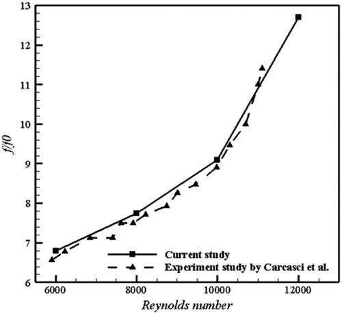
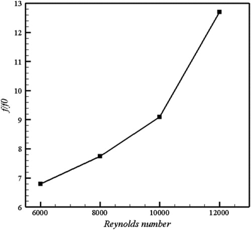
The variation of the friction factor ratio with Reynolds number in this numerical study is depicted in . The present numerical results for the friction factor are found to be in excellent agreement with experimental data by Carcasci et al. [Citation10] that provided in . This figure shows that the friction factor can be increased significantly by altering the inlet velocity profile. The normalized friction factor shows an increase at higher Reynolds number. The restrictions in the sub channels of this geometry influence the friction factor.
Figure 11. Friction factor ratio for different Reynolds numbers in static case.
shows the thermal performance factor for the present study at different Reynolds numbers. The thermal performance factor varies in the range of 1–1.3.
Figure 12. Thermal performance for different Reynolds numbers in static case.
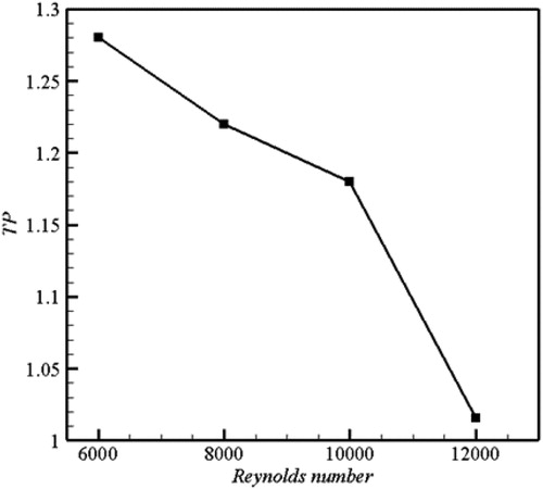
As the Reynold numbers is increased, the thermal performance factor for all cases is decreased. At the lower Reynolds numbers, the friction factor is low, so we have better thermal performance at lower Reynolds numbers.
3.3. Rotating channel
In the rotating state, the boundary conditions specified above are considering and according to direction of rotation, rotation effects are examined for this matrix geometry.
In rotational state cases, it is clear that in the smooth and ribbed passages, rotation-induced secondary flow (Buoyancy and Coriolis forces) enhances the heat transfer on the trailing surface (pressure-side), but reduces the heat transfer on the leading surface (suction-side).
shows the temperature contours on the top and bottom surfaces at Re = 12000 and Ro = 0.25. In this figure also the sub-channel numbering and the leading and trailing surfaces are specified.
Figure 13. Temperature distribution contours in the Rotary rectangular channel with matrix geometry for (a) top surface and (b) bottom surface.
Impingement and turning region strengthened heat transfer in these two surfaces too due to the matrix configuration. A comparison between and in particular, shows that in the rotational state opportunities for increasing heat transfer are present because according to the selected direction of rotation, the leading (Suction side) and trailing (Pressure side) surfaces interact with impingement and turning region on the side walls of the matrix geometry. This interaction leads to increased heat transfer and further reduction of temperature. Also, by comparing figures a and b below, it can be seen that for the trailing surface in top and bottom surfaces one has better heat transfer due to the accumulation of Buoyancy and Coriolis forces. The Coriolis force creates a swirl action on the spent flow and also deflects the jet direction when it is parallel to the rotation direction. According to the temperature difference between the coolant and the sub-channels in rotational conditions, the Buoyancy force makes the channels to reach high heat transfer, of course with regards to the direction of rotation close to the trailing side of the walls. The Buoyancy combines the effects of density ratio, rotation number, and a geometric configuration parameter (radius ratio) [Citation24].
It is worth mentioning that effect of Buoyancy and Coriolis force on the matrix cooling is greater than for the ribbed channels according to sub-channels segmentation.
shows the stream-wise distributions in the middle region of the 6th to 10th sub-channels at Re = 6000 and Ro = 0.25. The rotating flow comparisons show that the orthogonal rotation exerts a very strong influence on both the levels of the wall heat transfer and also on the local Nusselt number variation, generally leading to stronger local variations. Higher heat transfer augmentation levels occur on the trailing surface than on the leading surface, this is a result of energetic flow near the trailing surface and slower stabilized flow near the leading surface. In summary, as the channel rotates, one observes increased heat transfer levels near the trailing side and decreased levels near the leading side.
Figure 14. Variation of Nu number ratio as function of dimensionless width in each sub-channels for (a) top surface and (b) bottom surface of matrix geometry in rotary state.
In the trailing surface, the Nusselt number ratio at the entrance of each channel and for the leading surface at the end of each channel was strengthened due to the impingement and turning region but the effect of these two regions is not as large as the effects of the trailing and leading surfaces. All of these point to the fact that a rotational state for this geometry leads to uniform temperature and heat transfer distribution.
By comparing this figure with , it can be seen that the added phenomena of the matrix geometry and the rotational phenomena result in high level of heat transfer.
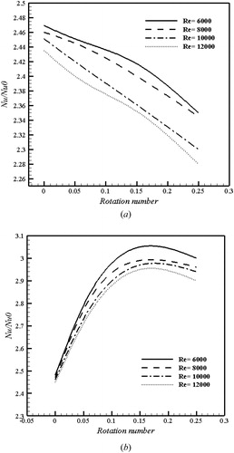
shows the Nu number ratio variation as function of Reynolds number and rotation number for the top and bottom surfaces. From , it can be seen that the Nusselt number ratios decrease with an increase in the rotation number. With increase of Reynolds number lower Nusselt number ratios in appear for all rotation numbers. This trend is slightly different in the bottom surface. shows that initially an increase in rotation number leads to high heat transfer but then the Nusselt number ratio reaches a maximum level close to a rotation number of 0.15 and then falls just before the highest rotation number. The effect of Reynolds number for this surface is similar to that reported in figure (a) but just at high rotation number. A comparison with the stationary state, the level of Nusselt number value relative to the smooth Nusselt number is somewhat higher than for the stationary state and the negative effect of rotation like damping of the secondary flows could not reduce the Nusselt number ratio for this case. At lower rotation numbers, the difference between various Reynolds numbers become less. At lower Reynolds numbers, it can be seen a greater dependence of Nusselt number on rotational number due to the effect of the entrance length of the coolant passage and induced secondary flow.
Figure 15. Variation of Nu number ratio as function of rotation number for various Reynolds number in (a) top surface and (b) bottom surface of matrix geometry in rotary state.
The variation of the friction factor ratio with Reynolds number for various rotation number is depicted in . The average friction coefficient ratio for all rotation numbers decreases with increasing Reynolds number. As expected, at higher rotation numbers, lower friction factor ratio occurs for each Reynolds number. It is noted that in a transient flow regime, the friction factor decreases sharply and has a constant value in the turbulent flow regime. Additionally, the friction factor ratios decreased by about 32 and 13% respectively, as the Reynolds number increased from 6000 to 10,000 and from 10,000 to 12,000, respectively.
Figure 16. Variation of friction factor ratio as function of Reynolds number for various rotation numbers in the middle region of two surfaces.
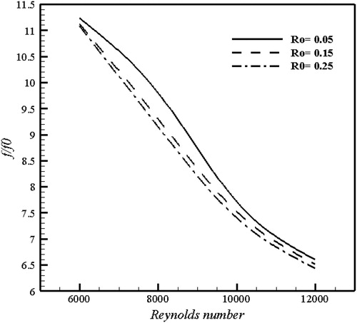
This particular insensitivity of the friction factor ratio to the rotation number at a given Reynolds number is evident in . Additionally, the friction factor ratios decreased by about 2–13% compared with for stationary state.
shows the thermal performance behavior as function of Reynolds and rotational number. For the range of rotational numbers considered in this study, it can be seen, that the heat transfer may be bad at higher rotation numbers. In this case, the rotation number 0.15 shows best thermal performance for all Reynolds numbers. The thermal performance factor at Re = 6000 increases from approximately 1.7–1.225 as the rotational numbers increased from 0.05 to 0.15 but after increasing the rotational number to 0.25, the thermal performance decreases to 1.2. As the Reynolds number increased, the thermal performance factor increased for all tested rotation numbers.
Figure 17. Variation of thermal performance as function of Reynolds number for various rotation number in the middle region of two surfaces.
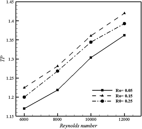
A comparison between and in particular, shows that the dependence of Reynolds number is decreasing in stationary state but in rotational state the thermal performance factor increases with increasing Reynolds number. Thermal performance appears to be in the range of 1.15–1.45 for all Reynolds and rotation numbers.
In summary, higher level of the thermal performance can be achieved for the rotational state about 5–12% compared with the stationary state for this geometry.
4. Conclusions
A numerical investigation has been carried out in order to analyze the stationary and rotational states and heat transfer phenomena in a matrix cooling geometry. Calculations were performed for one configuration with smooth walls and one with a matrix configuration which has two layered rectangular sub-channels and the rib angle is 45°. The results are summarized as below:
In the stationary state of Matrix cooling, the coolant passage provides very uniform streamwise temperature distribution in each layer of the matrix geometry. The heat transfer in top and bottom surfaces of the stationary case are almost equal.
At inlet and outlet of each sub-channel path in the stationary case, the impingement regions have more heat transfer and almost 50% higher than those in the turning region. Nusselt number ratio values in the impingement region were in the range of 3–4.5, while in the turning region corresponding values were in the range of 1.6–2.2.
It can be seen that the enhancement level of the Nusselt number relative to the smooth channel is about 2–2.5 and this is a significant advantage of the matrix configuration. These enhancement levels agree well with the stationary latticework passage results of Saha et al. [Citation13] and Carcasci et al. [Citation10].
In rotational state cases, it is clear that in the smooth and ribbed passages, rotation-induced secondary flow (Buoyancy and Coriolis forces) enhances the heat transfer on the trailing surface (Pressure-side), but reduces the heat transfer on the leading surface (Suction-side). For this case, an appropriate situation exists for increasing the heat transfer because according to the selected direction of rotation, the leading and trailing surfaces interact with the impingement and turning region on the side walls of the matrix geometry and accordingly higher heat transfer than for the stationary state is achieved.
Considering Nusselt number ratios in stationary and rotational states in the middle sub-channels, it is found that that rotation affects the trailing surface more and the heat transfer of this layer became more increased. At the leading edge a little increase in heat transfer due to rotational condition can be seen.
In rotational state at higher Reynolds number (Re ≥ 10,000) no significant rotation effects are observed on heat transfer; but at lower Reynolds number the situation is better. Also, the increase in heat transfer for the trailing surface at lower Reynolds number is about a factor of 3.
In the rotational state, the Nusselt number ratio at the leading surface decreases with increasing rotational number, but for trailing surface it is the vice versa and better heat transfer can be achieved at higher rotational number.
Changes in the friction factor ratio with Reynolds number in the rotational state are different from the stationary state. In the rotational state, it decreases with increasing Reynolds number but in the stationary case it increases with increasing Reynolds number. Also the range of the frictional factor ratios in the rotary case is less. Friction factors are relatively insensitive to an increase in the rotation.
The thermal performance factor appears to be in the range of 1.15–1.45 in the rotational case and in range of 1–1.3 for the stationary case at the same Reynolds number. But according to different trends of the friction factor ratio with Reynolds number, the changes in thermal performance factors are different for these two states. The best thermal performance in the stationary state is at lower Reynolds number but in the rotational state it is at Re = 12,000 and Ro = 0.15.
The conditions given above prove that one should choose the best geometry of the matrix cooling channel for each specified condition to achieve the highest thermal performance.
| Nomenclature | ||
| = | Specific heat ( | |
| DH | = | Hydraulic diameter based on the test channel, |
| f | = | Friction factor |
| f0 | = | Friction factor in a smooth rectangular channel |
| h | = | Heat transfer coefficient ( |
| H | = | Channel height (mm) |
| k | = | Thermal conductivity ( |
| L | = | Channel length (mm) |
| N | = | Number of cells in intended area |
| Nu | = | Nusselt number ( |
| Nu0 | = | Nusselt number in a smooth rectangular channel |
| = | Average Nusselt number | |
| = | Nusselt number at the x location | |
| ΔP | = | Pressure drop (Pa) |
| Pr | = | Prandtl number ( |
| q | = | Heat transfer rate (W) |
| = | Heat transfer per unit area (W) | |
| Re | = | Reynolds number ( |
| Ro | = | Rotation number ( |
| = | Bulk Temperature (K) | |
| Tw | = | Wall temperature (K) |
| = | Bulk temperature at the x location (K) | |
| U | = | Mean velocity ( |
| W | = | Channel width (mm) |
| = | Inlet total width of test model (mm) | |
| X | = | Coordinate and distance in the streamwise location |
| Y | = | Widthwise coordinate |
| Z | = | Span-wise coordinate |
| Greek symbols | ||
| = | Dynamic viscosity ( | |
| ρ | = | Density of air ( |
| = | Angular velocity (rad/ | |
| Subscripts | ||
| avg | = | Average |
| b | = | Bulk |
| t | = | Total |
| w | = | Wall |
| x | = | x location |
| Abbreviations | ||
| TP | = | Thermal performance |
References
- J. C. Han, Y. M. Zhang, and C. P. Lee, “Influence of surface heat flux ratio on heat transfer augmentation in square channels with parallel, crossed, and V-shaped angled ribs”, ASME J. Turbomach., vol. 114, no. 4, pp. 872–880, 1992. DOI:10.1115/1.2928042.
- G. Laschet, S. Rex, D. Bohn, and N. Moritz, “3-D conjugate analysis of cooled coated plates and homogenization of their thermal properties,” Numerical Heat Transfer: Part A: Appl., vol. 42, no. 1-2, pp. 91–106, 2002. DOI:10.1080/10407780290059440.
- P. R. Chandra, C. R. Alexander, and J. C. Han, “Heat transfer and friction behaviors in rectangular channels with varying number of ribbed walls,” Int. J. Heat Mass Transf., vol. 46, no. 3, pp. 481–495, 2003. DOI:10.1016/S0017-9310(02)00297-1.
- S. Y. Won, G. I. Mahmood, and P. M. Ligrani, “Flow structure and local Nusselt number variations in a channel with angled crossed-rib turbulators,” Int. J. Heat Mass Transf., vol. 46, no. 17, pp. 3153–3166, 2003. DOI:10.1016/S0017-9310(03)00103-0.
- R. S. Bunker, “Lattice work (vortex) cooling effectiveness part 1: Stationary channel experiments,” Power Land, Sea Air. ASME Turbo Expo GT2004-54157, Vienna, Austria, 2004.
- S. Acharya, F. Zhou, J. Lagrone, G. Mahmood, and R. Bunker, “Latticework (Vortex) cooling effectiveness part 2: rotating channel experiments,” ASME Turbo Expo, Vienna, Austria, June 14–17, ASME Paper No. GT2004-53983, 2004.
- S. Acharya, F. Zhou, J. Lagrone, G. Mahmood, and R. Bunker, “Latticework (vortex) cooling effectiveness: rotating channel experiments”, ASME J. Turbomach., vol. 127, no. 3, pp. 471–478, 2005. DOI:10.1115/1.1860381.
- K. Saha, S. H. Guo, S. Acharya, and C. Nakamata, “Heat transfer and pressure measurements in a lattice-cooled trailing edge of a turbine airfoil,” Power Land Sea Air, ASME Turbo Expo GT2008-51324, Berlin, Germany, 2008.
- P. G. Siddappa, R. S. S. Reddy, and U. Mallikarjun, “Matrix cooling configuration: a computational study,” Int. J. Mech. Prod. Eng., vol. 2, no. 9, pp. 1–5, 2014.
- C. Carcasci B. Facchini, M. Pievaroli, L. Tarchi, A. Ceccherini, and L. Innocenti, “Heat transfer and pressure loss measurements of matrix cooling geometries for gas turbine airfoils,” ASME J. Turbomachinery, vol. 136, no. 12, pp. 121005 (1–8), 2014.
- Y. Rao and S. Zang, “Flow and heat transfer characteristics in latticework cooling channels with dimple vortex generators,” ASME J. Turbomach., vol. 136, no. 2, pp. 021017 (1–10), 2014.
- I. Oh, K. Kim, D. Lee, J. Park, and H. Cho, “Local heat/mass transfer and friction loss measurement in a rotating matrix cooling channel,” ASME J. Heat Transfer, vol. 134, no. 1, pp. 011901 (1–9), 2011.
- K. Saha, S. Acharya, and C. Nakamata, “Heat transfer enhancement and thermal performance of lattice structures for internal cooling of airfoil trailing edges,” ASME J. Thermal Sci. Eng. Appl., vol. 5, no. 1, pp. 011001 (1–9), 2013.
- C. Carcasci, B. Facchini, M. Pievaroli, L. Tarchi, A. Ceccherini, and L. Innocenti, “Heat transfer and pressure drop measurements on rotating matrix cooling geometries for airfoil trailing edges,” ASME Turbo Expo. Montréal, Canada, June 15–19, ASME Paper No. GT2015-42594, 2015.
- E. Tian, H. Ya-Ling, and W. Tao, “Numerical simulation of finned tube bank across a staggered circular-pin-finned tube bundle,” Numer. Heat Transfer Part A Appl., vol. 68, no. 7, pp. 737–760, 2015. DOI:10.1080/10407782.2015.1012855.
- J. Zhou, X. Wang, J. Li, and H. Lu, “CFD analysis of mist/air film cooling on a flat plate with different hole types,” Numer. Heat Transf. A Appl., vol. 71, no. 11, pp. 1123–1140, 2017. DOI:10.1080/10407782.2017.1337994.
- Y. Zhang and A. Faghri, “Numerical simulation of condensation on a capillary grooved structure,” Numer. Heat Transfer A Appl., vol. 39, no. 3, pp. 227–243, 2001. DOI:10.1080/104077801300006562.
- A. Azzi, M. Abidat, B. A. Jubran, and G. S. Theodoridis, “Film cooling predictions of simple and compound angle injection from one and two staggered rows,” Numer. Heat Transfer A Appl., vol. 40, no. 3, pp. 273–294, 2001. DOI:10.1080/10407782.2001.10120637.
- M. R. Safaei, H. Togun, K. Vafai, S. N. Kazi, and A. Badarudin, “Investigation of heat transfer enhancement in a forward-facing contracting channel using FMWCNT nanofluids,” Numer. Heat Transfer A Appl., vol. 66, no. 12, pp. 1321–1340, 2014. DOI:10.1080/10407782.2014.916101.
- L. Wang and B. Sunden, “Experimental investigation of local heat transfer in a square duct with continues and truncated ribs,” Exp. Heat Transfer, vol. 18, no. 3, pp. 179–197, 2005. DOI:10.1080/08916150590953397.
- W. M. Rohsenow, J. P. Hartnett, and Y. I. Cho, Handbook of Heat Transfer. New York, NY: McGraw-Hill, 1998.
- J. Han, J. S. Park, and C. Lei, "Heat transfer and pressure drop in blade cooling channels with turbulence promoters.” Technical Report, NASA, Washington, DC, 1984.
- J. Han and J. S. Park, “Developing heat transfer in rectangular channels with rib turbulators,” Int. J. Heat Mass Transf., vol. 31, no. 1, pp. 183–195, 1988. DOI:10.1016/0017-9310(88)90235-9.
- G. Croce, H. Beaugendre, and W. Habashi, “Numerical simulation of heat transfer in mist flow,” Numer. Heat Transfer A Appl., vol. 42, no. 1–2, pp. 139–152, 2002. DOI:10.1080/10407780290059477.