
 ?Mathematical formulae have been encoded as MathML and are displayed in this HTML version using MathJax in order to improve their display. Uncheck the box to turn MathJax off. This feature requires Javascript. Click on a formula to zoom.
Abstract
In this study, effects of various geometrical parameters of a new winglet longitudinal vortex generator (LVG) on heat transfer and flow characteristics in a rectangular channel were investigated by a numerical method, and the influence of various parameters was analyzed. A comparative study of effects of elliptical pole parameters, the thickness, the length, the height, the attack angle, the transverse pitch and the longitudinal pitch of LVGs on heat transfer and pressure loss performance was conducted. The results showed that the intensity of heat transfer could be greatly increased by the increase of the length, the height, the attack angle and the transverse pitch of LVGs, accompanied with an increase of pressure drop. The Nusselt number decreased by increasing the longitudinal pitch of LVGs. The short axis and major axis of the elliptical poles and the thickness of LVGs had a small influence on the average heat transfer coefficient and average friction factor at the present condition. The design parameters of this configuration were optimized by the Taguchi method. Sixteen kinds of models were made by compounding levels on each factor, and heat transfer and flow characteristics of each model were analyzed. The results allowed us to quantitatively estimate the various parameters affecting heat transfer performance, and the main factors for optimal design of a rectangular channel with LVGs were selected. The optimal condition was also acquired by two analytical results.
1. Introduction
In a previous article [Citation1], the effects of six types of longitudinal vortex generator (LVG) configurations (Case A–F) on heat transfer and flow friction characteristics in a rectangular channel were investigated by a numerical method, and the heat transfer enhancement of LVGs was analyzed by the field synergy principle. Moreover, the comprehensive heat transfer performance of the mentioned channels was compared by the performance evaluation parameter, JF factor. The results showed that the common-flow-up delta winglet combined with elliptical pole configuration (Case F) was a suitable configuration to enhance the overall heat transfer performance for channels. From the preliminary study in [Citation1], the fundamental mechanism of heat transfer enhancement by these LVGs was the improvement of the synergy between the velocity and temperature gradients. The major purpose of this article is to present the influence of major parameters and optimization for Case F. There are some related reports for the parameter influence of LVGs [Citation2–26]. Sohankar and Davidson [Citation2] investigated heat transfer and unsteady flow characteristics in a channel with inclined block shape vortex generators (VGs) mounted on one side of the channel for different Reynolds numbers. The effects of the angle of incidence and the size of VGs were studied. Yakut et al. [Citation3] experimentally studied the tapes with double-sided delta-winglets under different geometrical and flow parameters in a test pipe. They pointed out that the winglet height was the most effective parameter for the friction factor, while the important parameter affecting the heat transfer was the Reynolds number. The optimum parameters of the turbulator were determined by the Taguchi experimental design method. Xie et al. [Citation4] numerically studied turbulent flow characteristics and heat transfer augmentation in a rectangular channel with elliptical cylinders and protrusions. The results showed that combinations of protrusion and elliptical cylinder geometries could give higher heat transfer rates than a case without protrusions. Additionally, Nusselt numbers increased with the increase of the height of protrusions and an optimum height-to-footprint diameter ratio was found. Khanjian et al. [Citation5] numerically studied the effect of the attack angle of the winglet on heat transfer and pressure drop in a channel. The results showed that the attack angle had a direct impact on heat transfer enhancement, and there was an optimum attack angle of the VG which led to the best enhancement. Jayavel and Tiwari [Citation6] numerically investigated heat transfer and flow characteristics in a channel with an inline arrangement of circular tubes in the presence of LVGs. The flow and temperature field results were analyzed to optimize the location of LVGs causing maximum enhancement in heat transfer with a minimum increase in pressure drop. Wu and Tao [Citation7] studied the average convective heat transfer on the top and bottom surfaces of a plain plate and four plates with a pair of delta winglet VGs punched directly from the plates at attack angles 15°, 30°, 45°, and 60°, respectively. Experimental results showed that the average Nusselt number on the plate surfaces increased with the increase of the attack angle of the delta winglet pair compared with that of a plain plate without a delta winglet pair in the test range. The average Nusselt number of the plate with attack angle 60° was slightly higher than that of the plate with attack angle 45° but brought a larger pressure drop. Caliskan [Citation8] experimentally investigated heat transfer and flow pressure drop performance of new punched triangular and rectangular LVGs with different attack angles. These arrangements significantly enhanced the heat transfer rate compared with the smooth plate surfaces. Pal et al. [Citation9] investigated heat transfer and flow characteristics for a fin-tube heat exchanger with different delta-winglet arrays in a common-flow-up configuration. The results showed that the decrease of the attack angle from 170° to 160° increased the heat transfer rate, but it also increased the pressure loss due to the extra drag induced by the winglet pairs. Salviano et al. [Citation10] numerically studied heat transfer and pressure drop of a two-row fin-and-tube heat exchanger with delta winglet LVGs in a staggered tube arrangement, and four LVG parameters were optimized by the genetic algorithm (GA) method. Skullong et al. [Citation11] experimentally investigated thermal performance improvement in a solar air heater channel with combined wavy-groove and delta winglet VGs placed on the absorber plate. The experimental results revealed that when the groove-wing distance to channel-height ratio was 0.5, the wing porosity area ratio 0.031 provided the highest Nusselt number and friction factor around 6 and 30 times higher than for the smooth channel, respectively. Zhang et al. [Citation12] developed several types of double delta winglets and double delta winglets with holes, and they examined the effects of the attack angle and the distance between delta winglets on heat transfer and flow characteristics in a rectangular channel. The results revealed that the larger angle and increasing distance could make an active role in the turbulent heat transfer enhancement. Ebrahimi et al. [Citation13] investigated the liquid flow and conjugated heat transfer performance of single-phase laminar flow in rectangular microchannels equipped with LVGs. Five different configurations of the microchannel with different attack angles of LVGs were considered. The results showed that for Reynolds number ranging from 100 to 1100, there was 2–25% increase in the Nusselt number for microchannels with LVGs, while the friction factor increased by 4–30%. The performance of all configurations of microchannels with LVGs was higher than that without LVGs. Khoshvaght-Aliabadi et al. [Citation14] experimentally and numerically studied the forced convective heat transfer for laminar and steady-state flow of copper-based deionized water nanofluid inside plate-fin channels with LVGs. Seven geometrical parameters (i.e., the winglet height, the winglet width, the channel length, the longitudinal winglet pitch, the transverse winglet pitch, and the winglet attack angle) were investigated on performance of a plate-fin heat exchanger with LVGs. Khoshvaght-Aliabadi et al. [Citation15] also experimentally and numerically studied heat transfer and flow characteristics of a channel with LVGs. The influences of seven effective geometrical parameters for three conventional coolants flowing in the laminar flow regime were evaluated. The results showed that the heat transfer coefficient and pressure drop increased as the winglet height, the longitudinal winglet pitch, and the transverse winglet pitch decreased and the winglet width, the channel length, and the winglet attack angle increased. The optimal location of winglets for maximum thermal compactness of a heat exchanger was studied by Arora et al. [Citation16]. The numerical results clearly showed that the optimally located common-flow-up delta winglets improved the average thermal performance of both the fins and the tubes at the same Reynolds number. Jin et al. [Citation17] numerically investigated the air-side heat transfer and pressure drop characteristics of an H-type finned tube bank in the turbulent periodically fully developed region. The effects of seven geometric parameters and Reynolds number were examined. Among the seven geometric parameters, the spanwise tube pitch had the most important effect. Liu et al. [Citation18] numerically and experimentally investigated the effects of the arrangement of winglets, the rotation angle of the combined winglets and the spacing between delta winglets on heat transfer and friction factors. The heat transfer characteristics were analyzed by the field synergy principle. Beigzadeh et al. [Citation19] developed a hybrid model, including the back-propagation network and the GA, for predicting heat transfer and flow characteristics in a rectangular channel with multiple twisted tape VGs. Dimensionless geometric parameters and Reynolds number were considered as network inputs, and Nusselt number and friction factor were output variables. Beigzadeh et al. [Citation20] also experimentally studied the effects of four interrupted plate fins with different geometric parameters on heat transfer and flow characteristics, and the computational fluid dynamics (CFD) modeling was undertaken and the simulation results were verified using the experimental data. The numerically validated data were used for developing two artificial neural networks (ANNs). Reynolds number and geometric parameters were determined as ANN inputs, and Nusselt number and friction factor were outputs. Gallegos and Sharma [Citation21] experimentally investigated heat transfer characteristics of rectangular channels equipped with a flapping flag as a VG. At uniform heat flux conditions, the effects of flow conditions, the channel size, the flag streamwise position and flag properties were discussed. Thermal and flow characteristics of plane and curved LVGs in a rectangular channel were numerically investigated by Lu and Zhou [Citation23], and the corresponding mechanism was analyzed by the field synergy principle. Wu et al. [Citation22] numerically investigated heat transfer and flow characteristics of turbulent forced convection of air flow through perforated circular pin fin heat sinks with constant heat flux. Circular perforated pin fins were shown to have 8% larger averaged Nusselt numbers than the corresponding solid pin cases. In addition, after the validation of the numerical results, the numerical optimization of this problem was also presented by using the response surface methodology coupled with GA. Dezan et al. [Citation24] performed a parametric study of heat transfer enhancement and the accompanied pressure loss applied to louvered fins with rectangular winglet VGs in a rectangular channel. The characteristics of heat transfer and flow resistance for five types of LVGs were studied numerically at the Reynolds number range of Re = 8,900–29,900 by Xu et al. [Citation25]. Luo et al. [Citation26] numerically studied the effects of convergence angles and dimple shapes on flow structure and heat transfer characteristics in a rotating dimple-pin fin wedge duct. The results indicated that the spanwise-elliptical dimple shape offered the best heat transfer augmentation as it generated the strongest vortex structure and turbulent kinetic energy in the dimples, and larger convergence angles exhibited larger Nusselt numbers and better heat transfer enhancement. From the above review, it is concluded that heat transfer and flow characteristics are affected significantly by the geometrical parameters of LVGs.
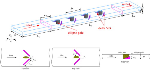
In the previous study [Citation27, Citation28], the effects of the attack angle, the length and height of LVGs on fin performance of a fin-and-tube heat exchanger with LVGs were studied. Based on the correlations of numerical simulation data, GA optimization was carried out, and the optimization results indicated that the increase of the attack angle and length of LVGs, and decrease of the height of LVGs could enhance the performance of the heat exchanger. Zeng et al. [Citation29] investigated the effects of eight parameters (i.e., the attack angle, the length, and the height of LVGs, the fin material, the fin thickness, the fin pitch, the longitudinal tube pitch and transverse tube pitch) on fin performance of a fin-and-tube heat exchanger with LVGs, and the parameters were optimized by the Taguchi method. The results showed that the six factors (i.e., the fin pitch, the longitudinal tube pitch, the transverse tube pitch, the length, height and attack angle of LVGs) had great influences on the JF factor. The fin material and fin thickness had trifling effects on the JF factor. Tang et al. [Citation30] also investigated the effects of geometrical parameters on heat transfer and flow characteristics of a fin-and-tube heat exchanger with common-flow-up LVG configurations by the numerical method. From the previous article [Citation1], we knew that Case F had the best overall heat transfer performance for channels. Are the geometrical parameters of Case F optimal? We don’t know. It encourages us to do more work to optimize the locations, orientation, and size of LVGs on the heat transfer surfaces to economically use LVGs in practical rectangular channels. Unfortunately, there is no detailed information about the optimal design parameters for rectangular channels with Case F in the literature. It is thus essential to investigate the effects of geometrical parameters on heat transfer and flow characteristics for Case F. The considered channel is shown in . In this study, the influence of various design parameters on heat transfer and flow characteristics for Case F is analyzed by the numerical method. The Taguchi method [Citation31, Citation32] is introduced into the present study for optimization and the database is also obtained by the numerical method. The results can provide us with quantitative estimation of the various parameters affecting performance, and the main factors for optimal design are selected. The optimal design value of each parameter is presented, and the reproducibility of the results is discussed.
Figure 1. Schematic diagram of the considered channel.
2. Numerical method
2.1. Governing equations and boundary conditions
The dimensionless governing equations for continuity, momentum, and energy may be expressed in vectorial notation as follows [Citation33].
(1)
(1)
In the above equation, the dependent variable, ϕ, stands for the velocity components, temperature, and turbulence properties. The terms Γϕ and Sϕ represent the appropriate diffusion coefficients and the source terms, respectively.
Because the governing equations are elliptic in spatial coordinates, boundary conditions are required for all boundaries of the computational domain. The required boundary conditions are described as follows:
Inlet boundary conditions: u = uin, v = w = 0, T=Tin.
Outlet boundary conditions:
Upper and side boundary conditions: u = v=w = 0, q = 0.
Lower boundary conditions: on the surface of the LVG, u = v=w = 0, q=constant; in the remaining part (L1 – length and L3 – length), u = v=w = 0, q = 0.
Meanwhile, no-slip boundary conditions are adopted on the surface of the LVG.
2.2. Numerical method
The foregoing governing equations and the boundary conditions are solved by the commercial CFD software ANSYS FLUENT 14.0. A preprocessor Gambit 2.4.6 is used to mesh the computational domain for the solver. The computational domain is discretized with uniform grids, with fine grids in LVG region to resolve the swirling flow and coarser grids in the other regions to save the computational resources. All variables, including velocity components, pressure, and temperature, are averaged for a control volume. The water-flow is assumed to be turbulent, quasi-steady, 3D and exhibiting no viscous dissipation. The coupling between pressure and velocity is implemented by the SIMPLEC algorithm. The QUICK method is used to discretize the convection terms. The shear stress transport (SST) k-ω turbulence model with low-Re corrections is adopted. The residuals are set to be less than 10−5 and 10−10 for continuity and energy equations, respectively, to ensure convergence of the computations. In order to validate the solution independence of the grid number, four different grid systems were investigated in details in the previous article [Citation1], and for simplicity there are not reported in this article.
2.3. Parameter definition
The Reynolds number (Re) is defined as
(2)
(2)
where uin is the bulk velocity of water, ρ is the water density, Dh is the hydraulic diameter, and μ is the dynamic viscosity of water.
The mean Nusselt number (Nu) is defined as
(3)
(3)
where λ is the thermal conductivity of water and the heat transfer coefficient, ho, is defined as
(4)
(4)
where qw is the heat flux, Tw is the local wall temperature of the channel bottom, and Tf is the mean temperature of the bulk fluid.
The Colburn j-factor is calculated by
(5)
(5)
The average Darcy friction factor (f-factor) is defined as
(6)
(6)
where Δp is the pressure loss along the channel domain, and L2 is the length of the channel.
3. The effects of various geometrical parameters
3.1. The effect of the elliptical pole parameter
From the previous article [Citation1], we know that Case F represents the configuration of common-flow-up delta winglet combined with elliptical pole in a rectangular channel. The effects of elliptical pole parameters are firstly investigated on heat transfer and pressure loss performance for Case F. The minimum lengths of short axis and major axis of the elliptical pole are chosen as 2 mm and 4 mm, respectively, for convenient fabrication. The major axis length varies from 4 to 8 mm and the other parameters are listed in .
Table 1. Geometric dimension of the LVG for Case F.
The effect of the major axis of the elliptical pole on the average Nusselt number and f-factor is shown in .
Figure 2. Nu and f-factor comparisons for various major axis lengths of the elliptical pole.
From , it can be seen the Nusselt number increases with increasing Reynolds number, while the f-factor decreases. There is no detectable variation of the Nusselt number and f-factor for various major axis lengths.
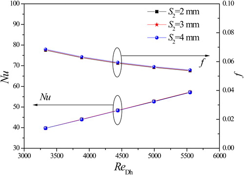
The effect of the short axis of the elliptical pole on the average Nusselt number and f-factor is shown in . The short axis length varies from 2 to 4 mm and the other parameters are kept the same as in . From , there is no detectable variation of the Nusselt number and only a slight variation of the f-factor for various short axis lengths. However, the numerical results show that the Nusselt number for S2 = 4 mm is the smallest and the f-factor is the largest, and the Nusselt number for S2 = 2 mm is the largest and the f-factor is the smallest. The reason can be explained as follows. The short axis of the elliptical pole is larger, and the value of the short axis is closer to that of major axis, so the elliptical pole is more similar to a circular pole. From the consideration of thermal hydraulics, the elliptical tube geometry offers significant advantages over the circular tube in the following aspects as depicted by Webb and Jung [Citation34]: 1. The fluid flow is normal to all of the narrow strips and the wake dissipation length is smaller; 2. A low wake region occurs behind the tubes; 3. The low projected area of the elliptical tube will result in lower profile drag.
Figure 3. Nu and f-factor comparisons for various short axis lengths of the elliptical pole.
The present results tell us that the parameters of the elliptical pole in the chosen range have trifling effects on heat transfer and pressure loss performance for Case F. The elliptical pole serves to create nozzle-like flow passages with the delta winglet pairs, where the water is accelerated to bring about a separation delay and form drag reduction of elliptical poles, and increase of the heat transfer enhancement.
3.2. The effect of the LVG thickness
The effect of the LVG thickness on heat transfer and pressure loss performance for Case F is shown in . The LVG thickness varies from 1.8 to 2.2 mm and the other parameters are kept the same as in .
Figure 4. Nu and f-factor comparisons for various LVG thicknesses.
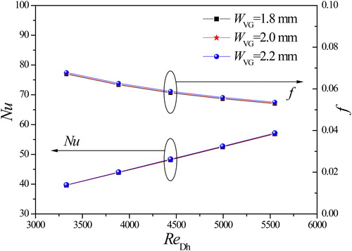
It shows that there is a little variation of the Nusselt number and f-factor for various LVG thicknesses. The numerical results show that the Nusselt number and f-factor of WVG = 1.8 mm are the lowest, the next is WVG = 2.0 mm, and the last one is WVG = 2.2 mm. The average Nusselt number and f-factor of WVG = 2.2 mm increase only 0.4% and 1.2%, respectively, compared to those of WVG = 1.8 mm in the range of the studied Reynolds number. Similar results were also described by Wu and Tao [Citation35]. The numerical results indicate that the LVG thickness has small influence on the average heat transfer performance and the average fictional factor of the channel.
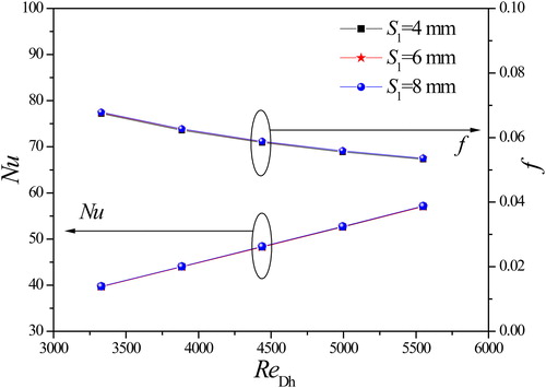
3.3. The effect of the LVG length
As can be seen in , we know that the size of LVG will decide the shielded part of the flow cross section in the spanwise direction. The effects of the LVG length on the average Nusselt number and f-factor are shown in . The length LVG varies from 10 to 18 mm and the other parameters remain the same as in .
Figure 5. Nu and f-factor comparisons for various LVG lengths.
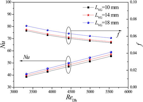
From , with the increase of Reynolds number, the Nusselt number increases and the f-factor decreases. The Nusselt number and f-factor increase with increasing LVG at the same Reynolds number. The reason can be explained as follows. The longitudinal vortices (LVs) are generated when the fluid flows over the side-edge of LVGs because of inertia and boundary layer separation. The number of generated LVs will increase with increasing LVG. presents the velocity distributions at different cross sections in the y-z plane of various LVG lengths at uin = 0.8 m/s.
Figure 6. Velocity distributions at different cross sections at uin = 0.8 m/s.
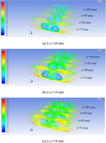
From , it can be observed that the LVs are generated at the leading edges and consist in the longitudinal direction, and with increasing LVG this can lead to two positive effects. One is that the distortion of the mean flow in the channel becomes stronger, and the total strength of the LVs increases. The other is that the transverse influence range of LVs becomes wider. Therefore, heat transfer enhancement is improved with increasing LVG. Meanwhile, with increasing LVG, the area of the LVGs also increases. This leads to an increase of the form drag of the LVGs and increased pressure drop in the channel.
3.4. The effect of the LVG height
Similar to LVG, the size of HVG will decide the shielded part of the flow cross section in the height direction. The effect of the LVG height HVG on the average Nusselt number and f-factor is shown in . The LVG height varies from 1.5 to 2.1 mm and the other parameters remain the same as in .
Figure 7. Nu and f-factor comparisons for various LVG heights.
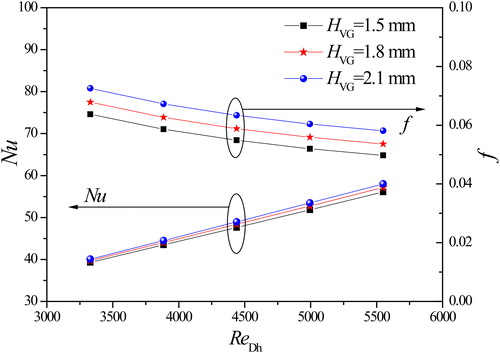
From , with the increase of Reynolds number, the Nusselt number increases and the f-factor decreases. The Nusselt number and f-factor increase with increasing HVG at the same Reynolds number. As is known, the cross-sectional flow area of the channel decreases as HVG is increased, and the fluid velocity at the side edge of the LVGs increases at the same volume flow rate. Therefore, the strength of the generated LVs increases, thus improving the heat transfer performance. The corresponding pressure drop is also increased. In this sense, these results are expected, because the heat transfer enhancement is usually penalized by the increase in pressure drop.
3.5. The effect of the LVG attack angle
The effect of the LVG attack angle β on the average Nusselt number and f-factor is shown in . The attack angle β varies from 15 to 44°.
Figure 8. Nu and f-factor comparisons for various LVG attack angles.
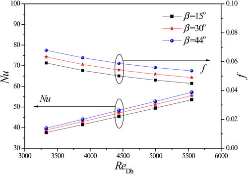
shows the Nusselt number and f-factor with Reynolds number for various attack angles. It can be seen that the Nusselt number increases with the increase of Reynolds number, while f-factor decreases. The Nusselt number of 44° is the highest among these attack angles at the same Reynolds number, that of 30° takes the second place, and that of 15° is the lowest. On the other hand, the f-factor of 44° is the highest, that of 30° also takes the second place, and that of 15° is the lowest. presents the velocity distributions at different cross sections in the y-z plane for various LVG attack angles at uin = 0.8 m/s.
Figure 9. Velocity distributions at different cross sections at uin = 0.8 m/s.
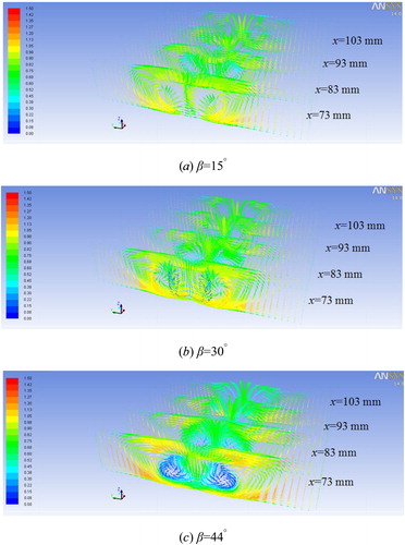
From , it can be observed that the distortion of the mean flow in the channel becomes stronger with increasing β in the studied range of attack angles. The larger attack angle makes LVG able to destroy the boundary layer more effectively and provide better airflow mixing. Therefore, the performance of heat transfer is enhanced, and the corresponding pressure drop is also increased.
3.6. The effect of the LVG transverse pitch
For examining the effect of the transverse pitch on the heat transfer and flow characteristics of Case F, the transverse pitch Pt varies from 4 to 6 mm. illustrates the variations of the Nusselt number and f-factor with the transverse pitch.
Figure 10. Nu and f-factor comparisons for various transverse pitches.
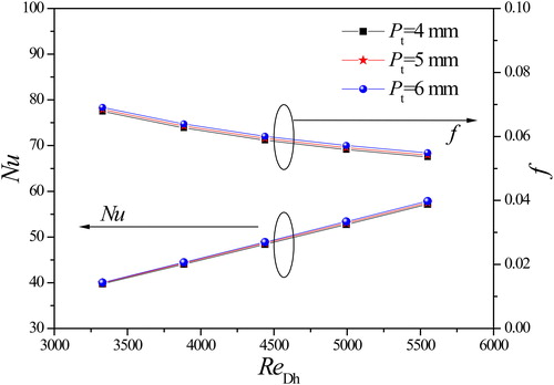
As shown in , the Nusselt number and f-factor increase with increase of the transverse pitch Pt. The average Nusselt number and f-factor of Pt = 6 mm increase 1.1% and 2.1%, respectively, compared to those of Pt = 4 mm in the range of the studied Reynolds number. The reason is that the LV pair generated by the LVG pair in the channel rotates in the opposite directions. With decreasing the transverse pitch, the interaction between the LV pair in their inner side becomes stronger. As a result, each vortex will be weakened by the others, hence, heat transfer is deteriorated and the heat transfer performance becomes worse. Therefore, for a given width of the channel, the transverse pitch between the LVG pair should not be too small, so that the two LVs generated will not interact with each other, and the spanwise LVnwiser. As a result, each vortex will be
3.7. The effect of the LVG longitudinal pitch
The effect of the longitudinal pitch on the heat transfer and flow characteristics of Case F is shown in . The longitudinal pitch Pl varies from 80 to 100 mm.
Figure 11. Nu and f-factor comparisons for various longitudinal pitches.
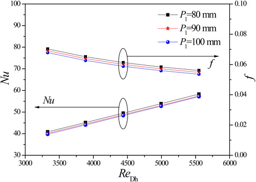
illustrates the variations of the Nusselt number and f-factor with various longitudinal pitches. As can be seen, the Nusselt number and f-factor decrease with increase of the longitudinal pitch. From in the previous article [Citation1], the influence intensity of vortices generated by LVGs is becoming weaker in the streamwise direction. Thus, the longitudinal pitch Pl is smaller, the average influence intensity of LV becomes stronger in the streamwise direction. As a consequence, the heat transfer performance is enhanced, and the f-factor of heat exchanger increases correspondingly.
4. The Taguchi method theory
4.1. Selection of characteristics
In general, the heat transfer and pressure drop characteristics are used to describe the performance of a heat exchanger. The research results show that the pressure drop will increase as the heat transfer is increased. So for the heat exchanger design, it is difficult to simultaneously increase the heat transfer and reduce the pressure drop. However, the design goal of a new heat exchanger is efficient heat transfer and low pressure drop. Therefore, a new parameter is defined to evaluate the heat transfer and pressure drop with the Taguchi method. The heat transfer and flow friction characteristics of heat exchangers are presented by j and f factors, respectively. In the present study, the JF factor, related to the j and f factors, is evaluated as the thermal-hydraulic performance for these cases. The JF factor is a dimensionless number of the larger-the-better characteristics, and is defined as follows [Citation36]
(7)
(7)
where jref and fref are the j and f factors of the smooth channel.
4.2. Factors and levels
As mentioned above, the parameters of the ellipse hole and the LVG thickness have trifling effects on heat transfer and pressure loss performance for Case F. Accordingly, the control factors used in this study are made up of the other five factors related to the heat transfer surface area and the turbulence on the water-side. The levels of each factor in this study are shown in . These factors are selected based on the numerical database. In this study, ReDh is taken as the signal factor but the noise factor is not considered.
Table 2. Levels of each factor in this study.
4.3. Orthogonal array
An orthogonal array of L16 (54) is established based on the numerical database in this study as shown in . The signal factor is applied to five simulation points.
Table 3. The orthogonal array of L16 (54).
4.4. SN analysis
The signal-to-noise (SN) ratio is used in quality engineering and experimental design and was invented by Taguchi. SN ratio (η) can help engineers to find out which levels of the control factors are more efficient. In the present study, the SN ratio of the dynamic characteristics is defined by the following equation
(8)
(8)
4.5. Analysis
The calculated SN ratios based on the 16 numerical simulation data are shown in . Factorial effect and contribution ratio of each factor are presented in and , respectively.
Figure 12. Contribution ratio of each factor.
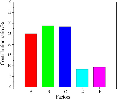
Table 4. SN ratio for each case.
Table 5. Factorial effect and contribution ratio.
The SN ratio of each factor in is derived from the arithmetic average of SN ratios corresponding to each level in . The R is the difference between maximum and minimum values of the SN ratio for every factor. The contribution ratio is equal to the value of the R number of each factor divided by the total R of all factors. The contribution ratio stands for the influence of every factor on the JF factor, which is the symbol of the thermal-hydraulic characteristics of a heat exchanger. Through the calculation, the contribution ratio of every factor can be evaluated as follows: 25.1% for the LVG length LVG, 28.8% for the LVG height HVG, 28.4% for the LVG attack angle β, 8.4% for the LVG transverse pitch Pt, and 9.3% for the LVG longitudinal pitch Pl. It shows that these three factors (LVG, HVG, and β) have a larger influence on the JF factor. Hence, they can be considered as the main factors for optimal design of a new heat exchanger due to the fact they are the main parameters related to the heat transfer and flow friction characteristics. It should be pointed out that the three parameters are normal parameters taken into account in the usual design process. However, note that the present results on the contribution ratio are limited to the effects of the five factors used in this study. Hence, to investigate the effects of factors other than those above, one can repeat a similar procedure.
shows the SN ratio of each factor to be considered in selecting the optimal condition. This means that the largest SN ratio level of all the levels on each factor has the best performance as mentioned above.
Figure 13. SN ratio of each factor.
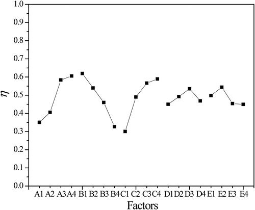
As shown in , for the LVG length LVG (factor A), level 4 (18 mm) is better. Level 1 (1.5 mm) is the best for the LVG height HVG. As far as the LVG attack angle β is concerned, 44° is the best. The advantage of the length, the height, and the attack angle is to disturb the boundary layer, which enhances heat transfer of the water-side, but the increasing pressure drop must be considered. The LVG transverse pitch Pt at the center indicates the optimal condition at the 6 mm level. Therefore, it is not good to recklessly decrease the LVG transverse pitch for the purpose of maximizing the velocity effect. The LVG longitudinal pitch has the optimal condition at the 80 mm level.
As shown above, it is confirmed that the factors related to the turbulence of water flow are very important parameters in the design of Case F.
4.6. Determination of the optimal condition
The optimal condition is obtained by a combination of levels showing the largest SN ratio in each control factor as presented in . As a result, two optimal conditions are especially selected in this work as shown in . Actually, only one optimal condition can be obtained using the present method, but a second-best optimal condition is considered in this study. Thus, one original optimal condition (optimal condition 2) is determined based on the Taguchi analysis method, and a second-best optimal condition (optimal condition 1) is selected to eliminate the error of the analysis. These two optimal conditions are A3B1C3D4E2 and A4B1C4D3E2, respectively.
Table 6. Optimal conditions from factorial effect analysis.
4.7. Reproducibility by confirmation test
The two test samples are designed by combining the five factors which are selected to be the optimal conditions as described above, and we have performed the confirmation test using these two samples. This is to confirm the reproducibility of the obtained results. These are divided into two methods.
The first method judges the degree of agreement between the presumed SN ratio for the optimal condition and the SN ratio of confirmation test results for the optimal samples. The presumed SN ratio, ηpre, is calculated using the factors with a contribution ratio among all factors as follows
(9)
(9)
Here, the numerical values of these five factors are taken from . The SN ratio of the optimal condition 2 is obtained directly from the confirmation test and is 0.8367. Thus, it is confirmed that there is reproducibility in this condition.
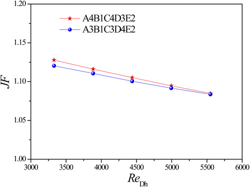
The second method is to confirm the reproducibility by direct comparison of the JF factor. shows the JF factor of the optimal configuration with Reynolds number. The JF factor of the optimal condition 1 is considerably higher than that of the optimal condition 2. It is thus demonstrated that the optimal condition 1 performs better than the optimal condition 2.
Figure 14. JF factor comparison of two optimal conditions.
5. Conclusions
In this study, the effects of various geometrical parameters of the LVG for Case F on heat transfer and flow characteristics were investigated by a numerical method, and the influence of various parameters was analyzed. The design parameters of Case F were optimized by the Taguchi method. The main conclusions were drawn as follows:
A comparative study of effects of the elliptical pole parameters, the thickness, the length, the height, the attack angle, the transverse pitch and the longitudinal pitch of LVGs on heat transfer and pressure loss performance was conducted. The results showed that the intensity of heat transfer could be greatly increased with the increase of the length, the height, the attack angle and the transverse pitch of LVGs, accompanying with the increase of pressure drop. The Nusselt number decreased with increasing longitudinal pitch of the LVG. The short axis and major axis of the elliptical pole and the thickness of the LVG had minor influence on the average Nusselt number and f-factor of Case F at the present condition.
It shows that the three factors of the LVG (the length, the height, and the attack angle) had great influences on the JF factor. There could be considered as the main factors for optimal design of a new heat exchanger due to the fact they were the main parameters related to the heat transfer and flow characteristics.
The optimal conditions of each factor were determined, and the two optimal conditions were A3B1C3D4E2 and A4B1C4D3E2, respectively. The reproducibility of these conditions was verified by two analytical results.
| Nomenclature | ||
| CFD | = | computational fluid dynamics |
| Dh | = | hydraulic diameter, mm |
| f | = | friction factor |
| GA | = | genetic algorithm |
| ho | = | heat transfer coefficient of fluid side, W/(m2·K) |
| H | = | height of the channel, mm |
| HVG | = | height of vortex generator, mm |
| j | = | Colburn factor |
| JF | = | JF factor |
| L1, L2, L3, L4 | = | channel length, mm |
| LVG | = | length of vortex generator, mm |
| LVG | = | longitudinal vortex generator |
| LVs | = | longitudinal vortices |
| N | = | number of vortex generator rows; number of tests |
| Nu | = | Nusselt number |
| Pl | = | longitudinal pitch, mm |
| Pt | = | transverse pitch, mm |
| Pr | = | Prandtl number |
| q | = | heat flux, W/m2 |
| R | = | difference between maximum and minimum values of SN ratio |
| Re | = | Reynolds number |
| S1 | = | major axis of elliptical pole, mm |
| S2 | = | short axis of elliptical pole, mm |
| Sϕ | = | source term, W/m3 |
| SN | = | signal-to-noise |
| T | = | temperature, K |
| = | velocity vector, m/s | |
| u, v, w | = | x, y, z velocity components, m/s |
| VG | = | vortex generator |
| W | = | width of the channel, mm |
| WVG | = | thickness of vortex generator, mm |
| x, y, z | = | Cartesian co-ordinates |
| Greek symbols | ||
| β | = | attack angle of vortex generator, ° |
| Γϕ | = | diffusion coefficient, m2/s |
| Δp | = | pressure drop, Pa |
| η | = | SN ratio |
| λ | = | thermal conductivity, W/(m·K) |
| μ | = | dynamic viscosity of fluid, kg/(m·s) |
| ρ | = | density, kg/m3 |
| ϕ | = | dependent variable |
| Subscripts | ||
| f | = | fluid |
| in | = | inlet |
| pre | = | presumed |
| ref | = | reference channel |
| w | = | channel wall |
Additional information
Funding
References
- L. H. Tang, W. X. Chu, N. Ahmed, and M. Zeng, “A new configuration of winglet longitudinal vortex generator to enhance heat transfer in a rectangular channel,” Appl. Therm. Eng., vol. 104, pp. 74–84, 2016. DOI: 10.1016/j.applthermaleng.2016.05.056.
- A. Sohankar and A. S. L. Davidson, “Effect of inclined vortex generators on heat transfer enhancement in a three-dimensional channel,” Numer. Heat Transfer, Part A, vol. 39, no. 5, pp. 433–448, 2001. DOI: 10.1080/10407780121572.
- K. Yakut, B. Sahin, C. Celik, N. Alemdaroglu, and A. Kurnuc, “Effects of tapes with double-sided delta-winglets on heat and vortex characteristics,” Appl. Energy, vol. 80, no. 1, pp. 77–95, 2005. DOI: 10.1016/j.apenergy.2004.03.003.
- G. N. Xie, Y. D. Song, and T. W. Simon, “Turbulent flow characteristics and heat transfer enhancement in a rectangular channel with elliptical cylinders and protrusions of various heights,” Numer. Heat Transfer, Part A, vol. 72, no. 6, pp. 417–432, 2017. DOI: 10.1080/10407782.2017.1386507.
- A. Khanjian, C. Habchi, S. Russeil, D. Bougeard, and T. Lemenand, “Effect of the angle of attack of a rectangular wing on the heat transfer enhancement in channel flow at low Reynolds number,” Heat Mass Transfer, vol. 54, no. 5, pp. 1441–1452, 2018. DOI: 10.1007/s00231-017-2244-8.
- S. Jayavel and S. Tiwari, “Numerical study of flow and heat transfer for flow past inline circular tubes built in a rectangular channel in the presence of vortex generators,” Numer. Heat Transfer, Part A, vol. 54, no. 8, pp. 777–797, 2008. DOI: 10.1080/10407780802359120.
- J. M. Wu and W. Q. Tao, “Effect of longitudinal vortex generator on heat transfer in rectangular channels,” Appl. Therm. Eng., vol. 37, pp. 67–72, 2012. DOI: 10.1016/j.applthermaleng.2012.01.002.
- S. Caliskan, “Experimental investigation of heat transfer in a channel with new winglet-type vortex generators,” Int. J. Heat Mass Transfer, vol. 78, pp. 604–614, 2014. DOI: 10.1016/j.ijheatmasstransfer.2014.07.043.
- A. Pal, D. Bandyopadhyay, G. Biswas, and V. Eswaran, “Enhancement of heat transfer using delta-winglet type vortex generators with a common-flow-up arrangement,” Numer. Heat Transfer, Part A, vol. 61, no. 12, pp. 912–928, 2012. DOI: 10.1080/10407782.2012.677322.
- L. O. Salviano, D. J. Dezan, and J. I. Yanagihara, “Optimization of winglet-type vortex generator positions and angles in plate-fin compact heat exchanger: response surface methodology and direct optimization,” Int. J. Heat Mass Transfer, vol. 82, pp. 373–387, 2015. DOI: 10.1016/j.ijheatmasstransfer.2014.10.072.
- S. Skullong, P. Promvonge, C. Thianpong, and M. Pimsarn, “Thermal performance in solar air heater channel with combined wavy-groove and perforated-delta wing vortex generators,” Appl. Therm. Eng., vol. 100, pp. 611–620, 2016. DOI: 10.1016/j.applthermaleng.2016.01.107.
- T. Zhang, Z. Q. Huang, X. B. Zhang, and C. J. Liu, “Numerical investigation of heat transfer using a novel punched vortex generator,” Numer. Heat Transfer, Part A, vol. 69, no. 10, pp. 1150–1168, 2016. DOI: 10.1080/10407782.2015.1125724.
- A. Ebrahimi, E. Roohi, and S. Kheradmand, “Numerical study of liquid flow and heat transfer in rectangular microchannel with longitudinal vortex generators,” Appl. Therm. Eng., vol. 78, pp. 576–583, 2015. DOI: 10.1016/j.applthermaleng.2014.12.006.
- M. Khoshvaght-Aliabadi, F. Hormozi, and A. Zamzamian, “Effects of geometrical parameters on performance of plate-fin heat exchanger: vortex-generator as core surface and nanofluid as working media,” Appl. Therm. Eng., vol. 70, no. 1, pp. 565–579, 2014. DOI: 10.1016/j.applthermaleng.2014.04.026.
- M. Khoshvaght-Aliabadi, S. Zangouel, and F. Hormozi, “Performance of a plate-fin heat exchanger with vortex-generator channels: 3D-CFD simulation and experimental validation,” Int. J. Heat Mass Transfer, vol. 88, pp. 180–192, 2015. DOI: 10.1016/j.ijthermalsci.2014.10.001.
- A. Arora, P. M. V. Subbarao, and R. S. Agarwal, “Numerical optimization of location of ‘common flow up’ delta winglets for inline aligned finned tube heat exchanger,” Appl. Therm. Eng., vol. 82, pp. 329–340, 2015. DOI: 10.1016/j.applthermaleng.2015.02.071.
- Y. Jin, Z. Q. Yu, G. H. Tang, Y. L. He, and W. Q. Tao, “Parametric study and multiple correlations of an H-type finned tube bank in a fully developed region,” Numer. Heat Transfer, Part A, vol. 70, no. 1, pp. 64–78, 2016. DOI: 10.1080/10407782.2016.1173433.
- H. L. Liu, C. C. Fan, Y. L. He, and D. S. Nobes, “Heat transfer and flow characteristics in a rectangular channel with combined delta winglet inserts,” Int. J. Heat Mass Transfer, vol. 134, pp. 149–165, 2019. 004. DOI: 10.1016/j.ijheatmasstransfer.2019.01.
- R. Beigzadeh, M. Rahimi, M. Parvizi, and S. Eiamsa-Ard, “Application of ANN and GA for the prediction and optimization of thermal and flow characteristics in a rectangular channel fitted with twisted tape vortex generators,” Numer. Heat Transfer, Part A, vol. 65, no. 2, pp. 186–199, 2014. DOI: 10.1080/10407782.2013.826010.
- R. Beigzadeh, M. Rahimi, O. Jafari, and A. A. Alsairafi, “Computational fluid dynamics assists the artificial neural network and genetic algorithm approaches for thermal and flow modeling of air-forced convection on interrupted plate fins,” Numer. Heat Transfer, Part A, vol. 70, no. 5, pp. 546–565, 2016. DOI: 10.1080/10407782.2016.1177329.
- R. K. B. Gallegos, and R. N. Sharma, “Heat transfer performance of flag vortex generators in rectangular channels,” Int. J. Therm. Sci., vol. 137, pp. 26–44, 2019. DOI: 10.1016/j.ijthermalsci.2018.11.001.
- C. H. Wu, H. W. Tang, and Y. T. Yang, “Numerical simulation and optimization of turbulent flows through perforated circular pin fin heat sinks,” Numer. Heat Transfer, Part A, vol. 71, no. 2, pp. 172–188, 2017. DOI: 10.1080/10407782.2016.1264727.
- G. Lu, and G. Zhou, “Numerical simulation on performances of plane and curved winglet–Pair vortex generators in a rectangular channel and field synergy analysis,” Int. J. Therm. Sci., vol. 109, pp. 323–333, 2016. DOI: 10.1016/j.ijthermalsci.2016.06.024.
- D. J. Dezan, J. I. Yanagihara, G. Jenovencio, and L. O. Salviano, “Parametric investigation of heat transfer enhancement and pressure loss in louvered fins with longitudinal vortex generators,” Int. J. Therm. Sci., vol. 135, pp. 533–545, 2019. DOI: 10.1016/j.ijthermalsci.2018.09.039.
- Z. M. Xu, Z. M. Han, J. T. Wang, and Y. F. Li, “The characteristics of heat transfer and flow resistance in a rectangular channel with vortex generators,” Int. J. Heat Mass Transfer, vol. 116, pp. 61–72, 2018. DOI: 10.1016/j.ijheatmasstransfer.2017.08.083,.
- L. Luo et al., “Convergence angle and dimple shape effects on the heat transfer characteristics in a rotating dimple-pin fin wedge duct,” Numer. Heat Transfer, Part A, vol. 74, no. 10, pp. 1611–1635, 2018. DOI: 10.1080/10407782.2018.1543920.
- L. H. Tang, M. Zeng, and Q. W. Wang, “Experimental and numerical investigation on air-side performance of fin-and-tube heat exchangers with various fin patterns,” Exp. Therm. Fluid Sci., vol. 33, no. 5, pp. 818–827, 2009. DOI: 10.1016/j.expthermflusci.2009.02.008.
- L. H. Tang, G. N. Xie, M. Zeng, M. Lin, and Q. W. Wang, “A comparative study of fin-and-tube heat exchangers with various fin patterns,” presented at the Proceedings of ASME Turbo Expo 2008: Power for Land, Sea, and Air, Aug. 2008, Berlin, Germany, pp. 1239–1246. DOI: 10.1115/GT2008-51504.
- M. Zeng, L. H. Tang, M. Lin, and Q. W. Wang, “Optimization of heat exchangers with vortex-generator fin by Taguchi method,” Appl. Therm. Eng., vol. 30, no. 13, pp. 1775–1783, 2010. DOI: 10.1016/j.applthermaleng.2010.04.009.
- L. H. Tang, S. C. Tan, P. Z. Gao, and M. Zeng, “Parameters optimization of fin-and-tube heat exchanger with a novel vortex generator fin by Taguchi method,” Heat Transfer Eng., vol. 37, no. 3–4, pp. 369–381, 2016. DOI: 10.1080/01457632.2015.1052715.
- G. Taguchi, E. A. Elsayed, and T. C. Hsiang, Quality Engineering in Production Systems. New York, USA: McGraw-Hill, 1989.
- R. K. Roy, A Primer on the Taguchi Method. 2nd ed. New York, USA: Society of Manufacturing Engineers, 2010.
- H. K. Versteeg and W. Malalasekera, An Introduction to Computational Fluid Dynamics: The Finite Volume Method. Essex, UK: Pearson Education, 2007.
- R. L. Webb and S. H. Jung, “Air-side performance of enhanced brazed aluminum heat exchangers,” ASHARE Trans., vol. 98, no. 2, pp. 391–401, 1992.
- J. M. Wu, and W. Q. Tao, “Numerical study on laminar convection heat transfer in a rectangular channel with longitudinal vortex generator. Part A: verification of field synergy principle,” Int. J. Heat Mass Transfer, vol. 51, no. 5–6, pp. 1179–1191, 2008. DOI: 10.1016/j.ijheatmasstransfer.2007.03.032.
- J. Y. Yun, and K. S. Lee, “Influence of design parameters on the heat transfer and flow friction characteristics of the heat exchanger with slit fins,” Int. J. Heat Mass Transfer, vol. 43, no. 14, pp. 2529–2539, 2000. DOI: 10.1016/S0017-9310(99)00342-7.