
 ?Mathematical formulae have been encoded as MathML and are displayed in this HTML version using MathJax in order to improve their display. Uncheck the box to turn MathJax off. This feature requires Javascript. Click on a formula to zoom.
Abstract
Endwall film cooling upstream of the leading edge (LE) of a vane presents a relatively complex flow phenomenon due to the horseshoe vortices (HVs) generated at the LE region. Upstream of the LE region, the coolant flow has difficulties to eject out. This research work focuses on controlling the jet holes coolant coverage upstream of the LE region. Compound angle holes in staggered arrangement are introduced and applied in the LE region to increase the coolant coverage. Six different arrangements of cooling holes are designed, with variations from one row or two rows arrangements, parallel or staggered arrangements, normal cylindrical holes or compound angle holes. Besides cooling holes with different shapes and arrangements, effect of the blowing ratio (BR) and turbulence intensity (TI) are also considered. The BR ranges from 1 to 3 and TI ranges from 1.3% to 15%. The calculated results show that the film cooling holes upstream of the LE of a vane have significant cooling effects on both the vane surfaces and the endwall. At small BRs, the film cooling effectiveness (η) on the endwall is considerable. When the BR is increased, the η on the vane surfaces is increased more quickly and becomes dominant. The coolant coverage in the vane-endwall junction region are not affected by the mainstream turbulence intensity and almost keep the same with the varied turbulence intensities. A single row of cylindrical holes (Case 1) and two rows of compound angle holes with staggered arrangement (Case 5) have relatively high overall averaged cooling effectiveness compared with other cases at different BRs. In addition, the high averaged cooling effectiveness on the endwall and vane surfaces by Case 5 is not affected by a change of the BRs.
1. Introduction
The design of advanced turbine blade cooling system is important to protect the blade from high turbine inlet temperature [Citation1, Citation2]. Film cooling provides high efficiency to protect a target surface from a high temperature mainstream by injecting coolant flows [Citation3]. This kind of cooling method is widely used in the cooling of a turbine blade, such as endwalls, blade surfaces, blade body and tip regions [Citation4, Citation5]. Due to the complex structures of a turbine blade and inherent complex flow field, it is difficult to have a good prediction of film cooling in the applications of gas turbines [Citation6]. The research on film cooling have involved several main aspects, such as pressure ratio, temperature ratio, the location, configuration and arrangements of film cooling holes in a specified blade [Citation7–10]. The effect of the mainstream turbulence intensity (TI), unsteady wake effect and the wall boundary effect are also considered in some research works [Citation11–13].
Endwall film cooling is relatively complex because of the complex flow fields caused by the horseshoe vortices [Citation14, Citation15]. A horseshoe vortex has strong transporting and rotating effect which will affect the coolant coverage on the protected surface. Not only the mainstream horseshoe vortex, the generated secondary vortices, such as passage vortex and generated corner vortices, strongly affect the flow field on the endwall.
1.1. Full-scale endwall film cooling
Full-scale endwall film cooling design has been investigated by many researchers [Citation16–22]. Granser and Schulenberg [Citation16] firstly measured the film cooling effectiveness (η) for a turbine vane shroud using thermocouples in a linear vane cascade. From their research work, the η near the suction side (SS) was higher than that near the pressure side (PS). Burd and Simon [Citation17] investigated the slot cooling upstream a nozzle guide vane (NGV) over a contoured endwall. They found the upstream bleed cooling had no effects on the aerodynamic penalty and had benefits in reducing secondary flow effects between vane passages. Oke et al. [Citation18, Citation19] measured the η on a contoured endwall using bleed holes upstream of a NGV. The coolant injection rates were controlled in the experiments. BR is an important parameter which affects the coolant coverage between the passages. Zhang and Jaiswal [Citation20] investigated the endwall fim cooling of a NGV using pressure sensitive paint (PSP), which use mass transfer method instead of traditional heat transfer method. They found that the averaged η had a nonlinear relation with the increased BRs which indicated the interference between coolant injections and endwall secondary flows. Knost and Thole [Citation21] measured full scale endwall η for NGV using IR camera. Two film cooling hole patterns with an upstream slot were tested. They found two regions, i.e., the LE region and pressure side with endwall junction region, were difficult to cool. Shiau et al. [Citation22] presented another full-scale endwall η distribution using the PSP methodology in a annular cascade. The work provides high resolution full-scale endwall η contours using a relative advanced measurement which provides good references for other researchers.
Not only full-scale film cooling design, but also one row or two rows of film cooling hole arrangements on a flat plate are investigated to give fundamental heat transfer and fluid flow characteristics for film cooling. These can also serve as the local design of arranging film cooling holes on a blade surface.
1.2. One row of film cooling holes
Sinha et al. [Citation23] measured a single row of holes with various density ratios using thermocouples. It is concluded that the variations in density ratio change the momentum flux ratio which affected the coverage and spreading of the coolant. Haas et al. [Citation24] investigated the influence of density ratio of coolant to mainstream by both predictions and experiments. In their research work, the η was increased with increased density ratio. Ligrani et al. [Citation25] used a single row of compound angle holes on a flat surface. They found that the coolant ejection from compound angle holes provided good film cooling protection with greatly increased coolant coverage. Goldstein and Jin [Citation26] measured the η of one row of compound angle holes using the naphthalene sublimation method. Similarly, when the compound angle holes are applied, the laterally-averaged η is enlarged compared with normal inclined holes at the same blowing ratio (BR). Effects of the hole length-to-diameter ratio [Citation27] and pitch-to-diameter ratio [Citation28] have been considered in some previous research works. In the recent years, more research works [Citation29] are concentrated on shaped holes to increase the cooling effectiveness, such as fan-shaped holes, which have exhibited higher effectiveness compared with normal cylindrical holes at higher BRs.
1.3. Two rows of film cooling holes
Jubran and Brown [Citation30] investigated the η with two rows of holes which are inclined in both the streamwise direction and spanwise direction. From their work, two rows of holes also showed improved film cooling compared to one row. Sinha et al. [Citation31] tested the flow field of two rows of holes related to gas turbine film cooling. Effect of boundary layer thickness was also considered. They found that the injection would penetrate strongly with a thick upstream boundary layer. Ligrani et al [Citation32] focused on two rows of compound film cooling holes with staggered arrangement to improve the η. They found that compound angle cooling holes had better cooling protection than simple inclined holes. Similarly, two rows of compound angle holes arrangements are found in some other research works [Citation33]. They all agreed that two rows of compound angle holes with staggered arrangement can significantly improve the cooling effectiveness. More recently, Dittmar et al. [Citation34] measured the η of compound angle holes arrangement using shaped holes. When the BRs are moderate or high, the fan-shaped holes show very good performance with increased coolant coverage in the spanwise direction.
From the above, endwall film cooling plays an important role in protecting the endwall and vane-endwall junction region. However, two regions on the endwall are difficult for application of film cooling due to the complex flow field, i.e., leading edge (LE) region [Citation35, Citation36] and endwall-PS junction region. Sundaram and Thole [Citation37, Citation38] investigated the film cooling at the LE of a NGV with trenched holes or bump modifications aiming at controlling the film cooling flow field. The LE region encountered strong flow impingement and high heat transfer. Previous works have found some useful conclusions from fundamental film cooling study. For example, the good coolant coverage by the compound angle holes and staggered arrangement are, respectively, better than normal cylindrical holes and parallel arrangements. However, related research works have not applied these findings in the design of film cooling at the LE region where the flow field is complex. In this research work, we want to apply the findings of one row or two rows of film cooling holes on a simple flat surface in designing the film cooling arrangement at the LE region of a turbine vane. Six different arrangements of cooling holes are designed, including one row or two rows, parallel or staggered arrangement, single inclination or compound angle holes. The cooling effectiveness and flow field details are analyzed and compared with numerical calculations.
2. Description of the computational domain
The computational domain is displayed in . The turbine vane adopted in this study is taken from the previous research works [Citation39] are shown in the left side of . The fluid domain is built based on the mid-line of the vane with upstream and downstream extended channels. The supply of the coolant at the LE is from a rectangular plenum for the cooling holes. The plenum is designed large enough to provide relatively uniform injection flows from each cooling hole. The mainstream Reynolds number (Re) is defined as
(1)
(1)
where C is the length of blade chord and u is the mainstream velocity. In this study, the mainstream Reynolds number is set as 220,000 and the corresponding blowing ratio ranges from 1 to 3.
Figure 1. Computational domain and various arrangements of film cooling holes.
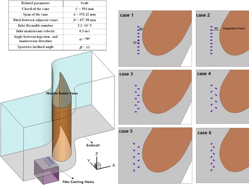
Six different arrangements of the film cooling holes are designed. Case 1 has one row of nine cylindrical holes placed at a distance of 4D from the stagnation point. The interval between two adjacent holes (p/D) is 3. Case 2 has the same arrangement as Case 1 but is placed more far away from the stagnation point (d = 8D). Case 3 has two rows of normal film cooling holes with staggered arrangement. The total number of the film cooling holes is unchanged with an interval of 6D. For Cases 4–6, compound angle holes are applied with the aim to combine the benefit of staggered arrangement and compound angle holes. Because of the specified region, upstream of the LE region, orientations of the compound angle holes have great effects. Case 4 has two staggered rows of film cooling holes with compound angle holes. The spanwise inclination angle of the row close to the vane (β) is 45° and that for the other row is −45°. Case 5 also use two rows of staggered arrangement but there have opposite spanwise inclination angle compared with Case 4. Case 6 has the same arrangement as Case 4 but relatively smaller interval between two rows. The injection angle in the streamwise direction is 30° for all the cases. The designed cases are shown below.
Case 1: one row, cylindrical holes, d = 4D;
Case 2: one row, cylindrical holes, d = 8D;
Case 3: two rows, cylindrical holes, d1= 6D, d2 = 8D;
Case 4: two rows, compound angle holes, d1= 4D, d2 = 8D, β1 = +45°, β2 = −45°;
Case 5: two rows, compound angle holes, d1= 4D, d2 = 8D, β1 = −45°, β2 = +45°;
Case 6: two rows, compound angle holes, d1= 6D, d2 = 8D, β1 = +45°, β2 = −45°;
3. Computational method and procedure
3.1. Mesh details
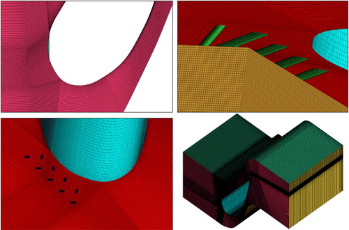
To enable high calculation accuracy, structured meshes are used and generated by ANSYS ICEM 17.1. The typical meshes used in this study are shown . The meshes are dense to meet requirement of the turbulence model in the near wall region, i.e. the wall y+ is around unity. The k-ω SST model is used based on the model validation which is provided in the next section.
Figure 2. Typical structured meshes in the leading edge region.
A mesh impendence study is performed for Case 2 at the BR = 1 and BR = 3. Three mesh systems are compared in , respectively, having 6.1 million, 8.7 million and 12.2 million cells. The averaged η of the endwall, SS and all surfaces are compared. The η is defined as
(2)
(2)
Table 1. Mesh indepence study.
The differences of the averaged cooling effectiveness predicted by different mesh systems are very small. The cooling effectiveness on the endwall region has a relatively high value with relatively small difference between different mesh systems at higher blowing ratio, BR = 3. The moderate mesh system, which has a mesh quantity of 8.7 million, has already provided a relatively accurate prediction. Considering the calculation resources and accuracy, the mesh system with a quantity of 8.7 million cells is used.
3.2. Boundary condition and solver
The inlet flow condition settings are based on the previous experimental studies [Citation39], which provide some conveniences for the later comparisons. The temperature difference of the mainstream and the coolant is set as 20 K and the properties of the air are assumed to be constant. Based on the previous experiments, the mainstream is specified at 6.3 m/s corresponding to Re of 2.2 × 10⁵. The mainstream is considered as fully developed turbulent flow when it approaches the leading edge. The mainstream is considered as incompressible because of the relatively low mainstream velocity. The effect of turbulence intensity is considered in this work with ranging from 1.3% to 15%. The inlet temperature of the mainstream is 320 K. The two sidewalls are periodic walls and built based on the middle line of the vane profile. There is a rectangular plenum to supply the coolant to the film cooling holes at the LE. The inlet of the plenum is set as mass-flow-inlet and the inlet mass flow temperature is set as 300 K. The flow flux of the plenum inlet is changed to obtain different BRs. Other walls are set as adiabatic walls with no-slip velocity. The outlet is set as pressure-outlet. If it is not specified, the figures in this work is created based on the turbulence intensities of 1.3% to easily compare the experimental work [Citation39, Citation40]. For all the considered cases, the turbulence intensity of film cooling holes is set as 5%.
The SIMPLEC method is applied for the coupling of pressure-velocity fields. Second order scheme is used for the discretization of the pressure, momentum, TKE, and specific dissipation rate and energy equations. The absolute criterion of 10−5 is set for the continuity equations and other flow field equations and 10−9 is chosen for the energy equation. Also, the average temperature of the endwall with as criterion of 10−5 is monitored to judge the convergence of the calculation.
3.3. Turbulence model
The k-ω SST model has advantages in dealing with the boundary layer region with high accuracy compared with other RANS models when applied in the turbomachinery. A comprehensive turbulence model validation is provided in and . Four different turbulent models, respectively, k-ω SST model, k-ε model, transition SST model and k-ε realizable model, are calculated and compared. The experimental data is obtained from [Citation40] by Kang et al. From the , all the turbulence models have pretty good predictions of the pressure coefficients compared with the experimental data. However, relatively large prediction errors exist after the transition part of the suction side. For different turbulence models, the predicted results are acceptable. The comparison of averaged Stanton numbers is shown in . The averaged Stanton number is increased in the streamwise direction. A little large error is also found at the transition region. The largest error between different turbulence models is still within 20% compared the experimental data. For other regions, the predicted heat transfer data is quite close to the experimental data. The k-ω SST model provides very good predictions for the pressure coefficients and Stanton numbers.
Figure 3. Turbulence model validations: comparisons of pressure coefficients and averaged Stanton number along the streamwise direction.
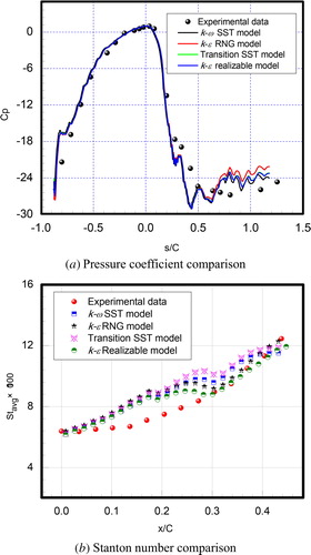
Figure 4. Turbulence model validations: comparisons of endwall film cooling effectiveness.
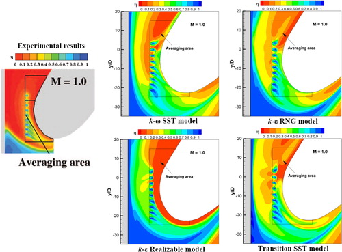
presents the comparison of the endwall η contours predicted by the different turbulence models with the experimental data. The pressure side has a relatively weak protection by the coolant from the film cooling holes at the LE. For different turbulence models, the predicted film cooling effectiveness distributions have similar forms. For the k-ε Realizable model, the errors of the film cooling effectiveness upstream of the vane are large. The film cooling holes at the stagnation region are uneasy to release. The cooling holes close to the suction side are easy to eject out. Considering all the comparisons, including the pressure coefficients, heat transfer and cooling effectiveness distributions, the k-ω SST model is selected.
4. Results and discussions
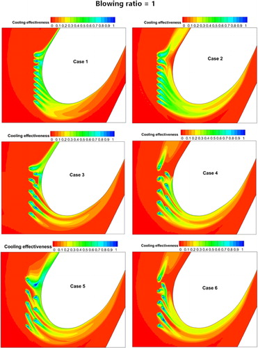
presents the endwall η contours for different cases at the BR = 1. The η contour at the LE is greatly affected by the impingement flows in the stagnation region. For Case 1, the LE region is well protected by one row of cooling holes when they are placed close to the stagnation point. When the cooling holes are placed a little far away, such as in Case 2, the coolant coverage near the stagnation region is insufficient. The ejected coolant flows are separated with by horseshoe vortices and develops with the mainstream flow. This kind of arrangement seems to eject the coolant in a large area along the SS and PS. However, for the two important regions, i.e., the stagnation region and junction region of the endwall and pressure side, this arrangement has no obvious improvements. Case 3 has two rows of normal cylindrical holes with staggered arrangement. This arrangement has good cooling protection for both the PS and SS. However, the cooling coverage is not as large as those in Case 1 and Case 2. Case 4 has two rows of compound angle cooling holes with staggered arrangement. The compound angle holes have reversed spanwise angles for each row. However, this arrangement almost has no good protection for the PS though the cooling coverage is relatively large on the endwall. In Case 6, the arrangement is similar to that in Case 4, but with a smaller interval between two rows. However, no obvious improvement can be found in Case 6. Case 5 also uses two rows of compound angle holes with staggered arrangement. The spanwise angles of two rows are totally reversed compared to those in Case 4. With reversed compound angles, the coolant coverage in Case 5 is greatly enlarged. The SS and PS of the vane are also protected well.
Figure 5. Endwall film cooling effectiveness for different cases at blowing ratio = 1.
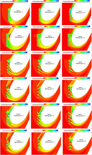
provides comparisons of η contours for all the cases at different BRs. With increased BR, the coolant strongly impinges on the LE and the generated horseshoe vortices develop deeply along the vane body. The strong impingement flows change the coherent flow path of the ejected coolant flows. Due to the high pressure at the stagnation region, the coolant sometimes has difficulties to eject out. The coolant coverage on the endwall is decreased when the BR is increased. It seems that coolant coverage at the LE of the vane is not so greatly affected in Case 2 and Case 5 even when the BR is increased. It is concluded that the film cooling holes at the LE of the vane also have good protection for the vane surfaces at the large BRs.
Figure 6. Endwall film cooling effectiveness for different cases at different blowing ratios.
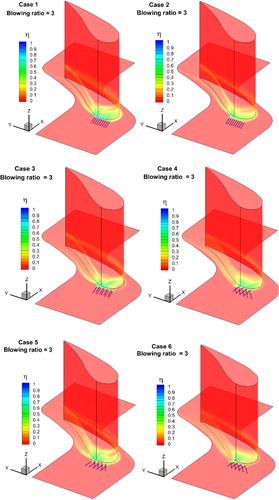
Three dimensional η contours for all the cases at BR = 3 are displayed in . It is clearly shown that the film cooling holes at the LE of the vane have effects both on the endwall region and the vane surfaces. Comparing Case 1 with Case 2, the coolant coverage on the vane surfaces is more dominant when the cooling holes are placed close to the LE. Case 3 also provides a good protection for both the SS and PS when the cylindrical holes have staggered arrangement. For the arrangements in Case 4 and Case 6, staggered arrangement with compound angle holes, have better coolant protection on the suction side than on the pressure side. In Case 5, staggered arrangement with reversed compound angle holes is utilized and this arrangement provides good protection for both the PS and SS. The figure provides more evidence that the junction region of the PS and endwall is difficult for the coolant to approach.
Figure 7. 3-D plot of film cooling effectiveness for different cases at blowing ratio = 3.
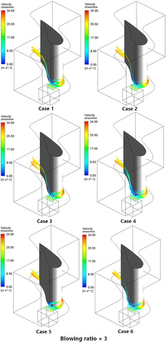
Three dimensional streamlines from the cooling holes for all the cases at a BR = 3 are displayed in . The coolant ejected from the cooling holes impinges on the vane surfaces and forms a HV originating from the LE. Most of the coolant flow is driven to the SS and little coolant is ejected to the PS, where high pressure exists. By controlling the arrangements of cooling holes, the coolant coverage at the pressure side can be increased. When the film cooling holes are placed close to the vane, the coolant combined with the mainstream strongly impinges on the vane surfaces. For Case 4 and Case 6, the coolant on the pressure side is lifted up, and hardly covers the junction region of the PS and the endwall. In addition, the velocity is gradually increased along the vane passages.
Figure 8. 3-D streamlines from the leading film cooling holes for different cases at blowing ratio = 3.
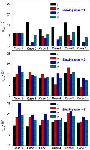
Comparisons of averaged η in different regions at different BRs are shown in . The averaged η in different regions are marked as η1, η2, η3 and η4, which, respectively, represent the averaged η on the whole endwall, the vane surface of pressure side, the vane surface of suction side and all the considered surfaces. From the table, Case 1 has relatively similar averaged cooling effectiveness for all the regions. When the cooling holes are placed a little far away from the vane LE (Case 2), the averaged η on the endwall is greatly enhanced while the averaged η on the vane surfaces is greatly reduced. Using staggered arrangement of the cooling holes (Case 3), the averaged η is improved on the vane surfaces at BR = 1. For the staggered arrangement with compound angle cooling holes, there are hardly no cooling effects at all on the vane surfaces of pressure side in Case 4 and Case 6. By reversing the compound angle of the cooling holes (Case 5), the η on the vane surfaces are greatly improved. In addition, the overall η of Case 5 is also the highest at the BR = 1. With the increased BR, the η on the vane surfaces and the overall averaged η are greatly increased. The cooling effects on the endwall are dominating when the BR is small and the cooling effects on the vane surfaces are dominant when the BR is large. Only in Case 5, the endwall η always has high levels at different BRs.
Table 2. Averaged film cooling effectiveness.
presents comparisons of averaged η in different regions. When the BR is 1, the averaged η in the region of suction side (η2) is relatively low in some cases, such as Case 2, Case 4 and Case 6. Other cases have larger averaged film cooling effectiveness than Case 1 when the BR is small. When the BR is increased, the film cooling effectiveness in all the regions is increased and the η is improved more significantly on the vane surfaces. Case 1 and Case 5 have good cooling performance in all the regions at different BRs. Case 5 also obtains high averaged overall cooling effectiveness.
Figure 9. Comparisons of averaged film cooling effectiveness in different regions.
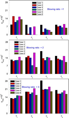
Comparisons of averaged η for different cases are shown in . Case 2 and Case 5 have better cooling effects on the endwall at low BR. When the BR is high, the cooling effectiveness on the endwall is decreased for Case 2. Cooling effectiveness on the SS is usually very low except for Case 5 which has better coolant coverage. The arrangement of Case 1 has provided the best η on the PS at different BRs. Case 1 and Case 5 have the best overall averaged cooling effectiveness. In general, Case 5 has relatively large cooling effectiveness in all the considered regions.
Figure 10. Comparisons of averaged film cooling effectiveness for different cases.
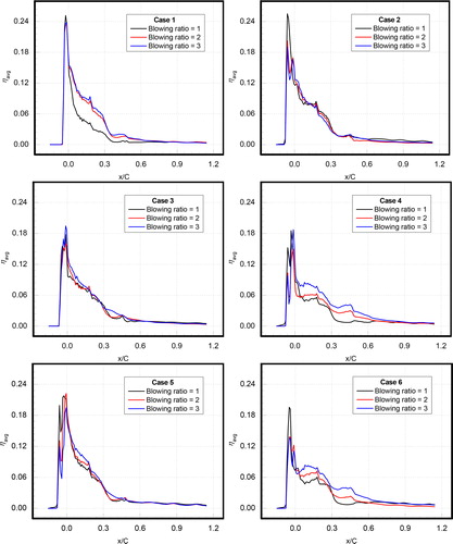
displays the averaged η along the streamwise direction on the endwall at different BRs. Each data point of the averaged cooling effectiveness is obtained by averaging a cluster of data in the lateral direction. The averaged cooling effectiveness is decreased along the streamwise direction. The highest cooling effectiveness is usually found at the region just before the LE region. However, the distribution trend is slightly different for different cases. Case 1 and Case 2 have the largest η in the LE region. For Case 1, the endwall film cooling effectiveness is not affected by the BR. For Case 1, Case 4 and Case 6, the η on the endwall in the passage region is affected by the BR. The cooling effectiveness is increased with increased BRs. Case 3 and Case 5 have similar distribution trends along the streamwise direction. In these cases, the coolant coverage expands deeply along the streamwise direction due to the staggered arrangement.
Figure 11. Laterally averaged cooling effectiveness on the endwall at different blowing ratios.
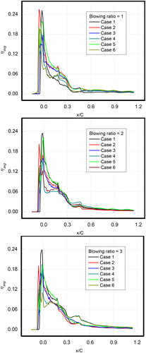
The averaged η on the endwall along the streamwise direction for different cases are presented in . In the LE region (x/C), the highest cooling effectiveness is obtained by Case 1 and Case 2. But the cooling effectiveness is decreased rapidly in the vane passage when x/C is larger than 0.3. In the region of x/C between 0.3 and 0.6, Case 4 and Case 6 obtain the largest η at the large BR. In the region when x/C is larger than 0.6, almost no cooling effect can be found on the endwall region. In general, the η on the endwall is increased slightly along the streamwise direction. Using the arrangements of Case 4 and Case 6, staggered arrangement using compound angle film holes, have not obtained high cooling effectiveness as that of Case 5.
Figure 12. Laterally averaged cooling effectiveness on the endwall for different cases.
presents the averaged η distributions along the spanwise direction at different BRs. The left part of the figure is the distribution on the pressure side and the right part is the distribution on the SS. Each data point in the spanwise direction is obtained by averaging all the data points on the x-y section. The averaged η is decreased along the vane spanwise direction and almost no cooling effects when z/Sp is larger than 0.2. With the increased BRs, the high cooling effectiveness region is expanded along the spanwise direction. Sometimes, the highest cooling effectiveness regions are not the junction part of pressure side and the endwall, such as Case 2 at the BR = 2 and Case 5 at the BR = 2. For the suction side surfaces, the highest cooling effectiveness regions are lifted to the vane surfaces at high BR. With increased BR, it is obvious that the high cooling effectiveness regions are moved along the spanwise direction. It is also clear that there is almost no cooling coverage on the PS at the low BR in Case 4 and Case 6.
Figure 13. Averaged film cooling effectiveness distributions on the vane surfaces along the spanwise direction at different blowing ratios.
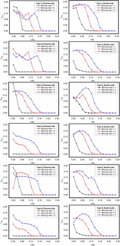
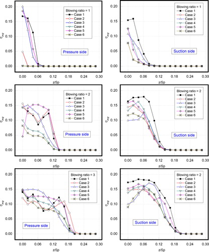
provides comparisons of averaged η along the spanwise direction for different cases. The distributions on the pressure side and SS are separated, respectively, located in the left and right sides of the figure. For the pressure side region, Case 1, Case 3 and Case 5 have relatively large cooling effectiveness at the low BR. When the BR is increased, the η of Case 2 and Case 5 are greatly increased and become the largest. Overall, all the cooling effectiveness is increased with increased BR on the PS. There is almost no cooling effects when z/Sp > 0.06 at BR =1, z/Sp > 0.15 at the BR = 2 and z/Sp > 0.2 at BR = 3. However, Case 5 always exhibits high performance at all the considered BRs. For the suction side region, the main difference is that the high η region is lifted up along the spanwise direction, not the junction region as it exists in the PS. Case 1 has the largest η on the SS at all considered BRs. The cooling coverage seems to expand deeper along the PS surface. In general, the film cooling holes upstream of the LE also have obvious cooling effects on the vane surfaces.
Figure 14. Averaged film cooling effectiveness distributions on the vane surfaces along the spanwise direction for different cases.
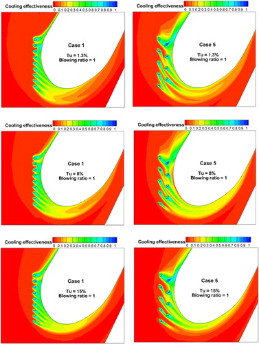
Contours of the endwall η for different inlet turbulence intensities are presented in . In general, the turbulence intensity has no obvious effect on the η distributions. However, a small influence is found on the coolant track of the SS. With increased turbulence intensities, the coolant coverage spreading on the endwall is suppressed and the coolant develops deeper along the vane surfaces for both Case 1 and Case 5. This means that the junction region of the vane and endwall is well protected at large turbulence intensity and the increased film cooling effectiveness are mainly found at the suction region.
Figure 15. Contours of endwall film cooling effectiveness at different inlet turbulence intensities for Case 1 and Case 5.
5. Summary and conclusions
This work concentrated on the arrangement of cooling holes upstream the LE of a turbine vane where the flow structure is complex. Six different arrangements of film cooling holes were designed in this specific region and the staggered arrangement and compound angle holes are included. The total number of the film cooling holes is constant with variations of one row or two rows, parallel or staggered arrangements, normal cylindrical holes or compound angle holes. The results were obtained numerical calculations with a well-established turbulence model, the k-ω SST model. Effects of BR and mainstream turbulence intensity are also considered. Some conclusions are given as follows.
The film cooling holes, upstream the LE of a vane, have cooling effects on both the vane surfaces and the endwall. At small BRs, the η on the endwall is dominating. When the BR is increased, the η on the vane surfaces is increased more quickly and become dominant. The ejected coolant flows from the film cooling holes combine with generated horseshoe vortex and develop along the vane passages. The overall averaged film cooling effectiveness is increased with increased BR. The vane–endwall junction region is better protected at the larger mainstream turbulence intensity.
Case 1 and Case 5 have relatively high overall averaged cooling effectiveness compared with other cases. Case 2 and Case 4 almost have no coolant coverage on the PS when the BR is low though they also have two rows of compound angle holes with staggered arrangement. Case 5, with reversed arrangement compared to Case 2 and Case 4, have relatively high averaged η on the endwall independent of the BR. The staggered two-rows arrangements with compound angle holes, Case 5, is recommended for the design of arranging film cooling holes upstream of the LE region.
| Nomenclature | ||
| Latin characters | = |
|
| C | = | chord of the vane (m) |
| d | = | interval between adjacent rows of cooling holes (m) |
| D | = | diameter of cooling holes (m) |
| L | = | length of cooling holes (m) |
| Pc | = | pitch between two cooling holes (m) |
| P | = | pitch between adjacent vanes (m) |
| Re | = | Reynolds number |
| Sp | = | span of the vane (m) |
| Tc | = | coolant temperature (K) |
| Tg | = | mainstream temperature (K) |
| Tu | = | turbulence intensity |
| u | = | mainstream velocity (m/s) |
| x | = | streamwise direction (m) |
| y | = | spanwise direction (m) |
| z | = | normal direction (m) |
| Greek symbols | ||
| α | = | angle bewteen injection and mainstream direction |
| β | = | spanwise inclined angle of film cooling holes |
| λ | = | thermal conductivity (W/m·K) |
| μ | = | fluid dynamic viscosity (Pa·s) |
| ρ | = | fluid density (kg/m3) |
| η | = | film cooling effectiveness |
| Subscripts | ||
| 1 | = | the row close to the vane |
| 2 | = | the row a little far from the vane |
| m | = | average/overall |
| w | = | wall |
| c | = | coolant |
| Abbreviations | ||
| BR | = | blowing ratio |
| HV | = | horseshoe vortice |
| LE | = | leading edge |
| PS | = | pressure side |
| SS | = | suction side |
| TKE | = | turbulence kinetic energy |
| TI | = | turbulence intensity |
Additional information
Funding
References
- W. Du, L. Luo, S. Wang and X. Zhang, “Flow structure and heat transfer characteristics in a 90-deg turned pin fined duct with different dimple/protrusion depths,” Appl. Therm. Eng., vol. 146, pp. 826–842, 2019. DOI: 10.1016/j.applthermaleng.2018.10.052.
- J. Liu, et al., “Application of fractal theory in the arrangement of truncated ribs in a rectangular cooling channel (4: 1) of a turbine blade,” Appl. Therm. Eng., vol. 139, pp. 488–505, 2018. DOI: 10.1016/j.applthermaleng.2018.04.133.
- R. J. Goldstein, “Film cooling,” in Advances in Heat Transfer, vol. 7. Amsterdam: Elsevier, 1971, pp. 321–379.
- D. G. Bogard and K. A. Thole, “Gas turbine film cooling,” J. Propulsion Power, vol. 22, no. 2, pp. 249–270, 2006. DOI: 10.2514/1.18034.
- J. F. Zhou, X. J. Wang, J. Li and H. K. Lu, “CFD analysis of mist/air film cooling on a flat plate with different hole types,” Numer. Heat Transfer Part A-Appl., vol. 71, no. 11, pp. 1123–1140, 2017. DOI: 10.1080/10407782.2017.1337994.
- S. Ito, R. Goldstein and E. Eckert, “Film cooling of a gas turbine blade,” J. Eng. Power, vol. 100, no. 3, pp. 476–481, 1978. DOI: 10.1115/1.3446382.
- R. S. Bunker, “A review of shaped hole turbine film-cooling technology,” ASME J. Heat Transfer, vol. 127, no. 4, pp. 441–453, 2005. DOI: 10.1115/1.1860562.
- S. Ekkad and J. C. Han, “A review of hole geometry and coolant density effect on film cooling,” ASME 2013 Heat Transfer Summer Conference Collocated with the ASME 2013 7th International Conference on Energy Sustainability and the ASME 2013 11th International Conference on Fuel Cell Science, Engineering and Technology, American Society of Mechanical Engineers, 2013, pp. V003T020A003.
- C. Wang, F. Fan, J. Zhang, Y. Huang and H. Feng, “Large eddy simulation of film cooling flow from converging slot-holes,” Int. J. Therm. Sci., vol. 126, pp. 238–251, 2018. DOI: 10.1016/j.ijthermalsci.2018.01.007.
- S. Lee, W. Hwang and K. Yee, “Robust design optimization of a turbine blade film cooling hole affected by roughness and blockage,” Int. J. Therm. Sci., vol. 133, pp. 216–229, 2018. DOI: 10.1016/j.ijthermalsci.2018.07.012.
- J. C. Han and S. Ekkad, “Recent development in turbine blade film cooling,” Int. J. Rotating Mach., vol. 7, no. 1, pp. 21–40, 2001. DOI: 10.1155/S1023621X01000033.
- N. J. Greiner, M. D. Polanka and J. L. Rutledge, “Impact of wall boundary condition on scaling film cooling performance from near ambient to engine temperatures,” Int. J. Therm. Sci., vol. 132, pp. 378–386, 2018. DOI: 10.1016/j.ijthermalsci.2018.06.004.
- K. Singh, B. Premachandran and M. R. Ravi, “Numerical investigation of film cooling on a 2D corrugated surface,” Numer. Heat Transfer Part A-Appl., vol. 70, no. 11, pp. 1253–1270, 2016. DOI: 10.1080/10407782.2016.1230431.
- K. Ghosh and R. J. Goldstein, “Effect of inlet skew on heat/mass transfer from a simulated turbine blade,” ASME 2011 Turbo Expo: Turbine Technical Conference and Exposition, American Society of Mechanical Engineers, 2011, pp. 1677–1687. DOI: 10.1115/GT2011-46543.
- C. C. Shiau, et al., “Turbine vane endwall film cooling comparison from five film-hole design patterns and three upstream leakage injection angles,” ASME Turbo Expo 2018: Turbomachinery Technical Conference and Exposition, American Society of Mechanical Engineers, 2018, pp. V05CT19A005.
- D. Granser and T. Schulenberg, “Prediction and measurement of film cooling effectiveness for a first-stage turbine vane shroud,” ASME 1990 International Gas Turbine and Aeroengine Congress and Exposition, American Society of Mechanical Engineers, 1990, pp. V004T009A020.
- S. W. Burd and T. W. Simon, “Effects of slot bleed injection over a contoured endwall on nozzle guide vane cooling performance: part I—Flow field measurements,” ASME Turbo Expo 2000: Power for Land, Sea, and Air, American Society of Mechanical Engineers, 2000, pp. V003T001A007.
- R. A. Oke, T. W. Simon, S. W. Burd and R. Vahlberg, “Measurements in a turbine cascade over a contoured endwall: Discrete hole injection of bleed flow,” ASME Turbo Expo 2000: Power for Land, Sea, and Air, American Society of Mechanical Engineers, 2000, pp. V003T001A022.
- R. Oke, et al., “Measurements over a film-cooled, contoured endwall with various coolant injection rates,” ASME Turbo Expo 2001: Power for Land, Sea, and Air, American Society of Mechanical Engineers, 2001, pp. V003T001A025.
- L. J. Zhang and R. S. Jaiswal, “Turbine nozzle endwall film cooling study using pressure sensitive paint,” ASME Turbo Expo 2001: Power for Land, Sea, and Air, American Society of Mechanical Engineers, 2001, pp. V003T001A030.
- D. Knost and K. Thole, “Adiabatic effectiveness measurements of endwall film-cooling for a first stage vane,” ASME Turbo Expo 2004: Power for Land, Sea, and Air, American Society of Mechanical Engineers, 2004, pp. 353–362. DOI: 10.1115/GT2004-53326.
- C. C. Shiau, A. F. Chen, J. C. Han, S. Azad and C. P. Lee, “Full-scale turbine vane endwall film-cooling effectiveness distribution using pressure-sensitive paint technique,” J. Turbomach., vol. 138, no. 5, pp. 51002, 2016. DOI: 10.1115/1.4032166.
- A. Sinha, D. Bogard and M. Crawford, “Film-cooling effectiveness downstream of a single row of holes with variable density ratio,” J. Turbomach., vol. 113, no. 3, pp. 442–449, 1991. DOI: 10.1115/1.2927894.
- W. Haas, W. Rodi and B. Schonung, “The influence of density difference between hot and coolant gas on film cooling by a row of holes: Predictions and experiments,” J. Turbomach., vol. 114, no. 4, pp. 747–755, 1992. DOI: 10.1115/1.2928028.
- P. Ligrani, J. Wigle and S. Jackson, “Film-cooling from holes with compound angle orientations: part 2—Results downstream of a single row of holes with 6D spanwise spacing,” ASME J. Heat Transfer, vol. 116, no. 2, pp. 353–362, 1994. DOI: 10.1115/1.2911407.
- R. Goldstein and P. Jin, “Film cooling downstream of a row of discrete holes with compound angle,” ASME Turbo Expo 2000: Power for Land, Sea, and Air, American Society of Mechanical Engineers, 2000, pp. V003T001A054.
- W. Li, X. Li, J. Ren and H. Jiang, “Large eddy simulation of compound angle hole film cooling with hole length-to-diameter ratio and internal crossflow orientation effects,” Int. J. Therm. Sci., vol. 121, pp. 410–423, 2017. DOI: 10.1016/j.ijthermalsci.2017.08.001.
- H. A. Zuniga and J. S. Kapat, “Effect of increasing pitch-to-diameter ratio on the film cooling effectiveness of shaped and cylindrical holes embedded in trenches,” ASME Turbo Expo 2009: Power for Land, Sea, and Air, American Society of Mechanical Engineers, 2009, pp. 863–872. DOI: 10.1115/GT2009-60080.
- A. F. Chen, S. J. Li and J. C. Han, “Film cooling for cylindrical and fan-shaped holes using pressure-sensitive paint measurement technique,” J. Thermophys. Heat Transfer, vol. 29, no. 4, pp. 775–784, 2015. DOI: 10.2514/1.T4518.
- B. Jubran and A. Brown, “Film cooling from two rows of holes inclined in the streamwise and spanwise directions,” J. Eng. Gas Turbines Power, vol. 107, no. 1, pp. 84–91, 1985. DOI: 10.1115/1.3239701.
- A. Sinha, D. Bogard and M. Crawford, “Gas turbine film cooling: Flowfield due to a second row of holes,” ASME 1990 International Gas Turbine and Aeroengine Congress and Exposition, American Society of Mechanical Engineers, 1990, pp. V004T009A011.
- P. Ligrani, J. Wigle, S. Ciriello and S. Jackson, “Film-cooling from holes with compound angle orientations: part 1—Results downstream of two staggered rows of holes with 3D spanwise spacing,” ASME J. Heat Transfer, vol. 116, no. 2, pp. 341–352, 1994. DOI: 10.1115/1.2911406.
- B. Jubran and B. Maiteh, “Film cooling and heat transfer from a combination of two rows of simple and/or compound angle holes in inline and/or staggered configuration,” Heat Mass Transfer, vol. 34, no. 6, pp. 495–502, 1999. DOI: 10.1007/s002310050287.
- J. Dittmar, A. Schulz and S. Wittig, “Assessment of various film cooling configurations including shaped and compound angle holes based on large scale experiments,” ASME Turbo Expo 2002: Power for Land, Sea, and Air, American Society of Mechanical Engineers, 2002, pp. 109–118. DOI: 10.1115/GT2002-30176.
- R. Hou, F. B. Wen, X. L. Tang, T. Cui and S. T. Wang, “Improvement of film cooling performance by trenched holes on turbine leading-edge models,” Numer. Heat Transfer Part A-Appl., vol. 76, no. 3, pp. 160–177, 2019. DOI: 10.1080/10407782.2019.1627832.
- K. N. Huang, J. Z. Zhang, C. H. Wang and Y. Shan, “Numerical evaluation on single-row trenched-hole film cooling performances on turbine guide vane under engine-representative conditions,” Numer. Heat Transfer Part A-Appl., vol. 76, no. 4, pp. 198–219, 2019. DOI: 10.1080/10407782.2019.1627830.
- N. Sundaram and K. Thole, “Bump and trench modifications to film-cooling holes at the vane-endwall junction,” J. Turbomach., vol. 130, no. 4, pp. 41013, 2008. DOI: 10.1115/1.2812933.
- N. Sundaram and K. Thole, “Film-cooling flowfields with trenched holes on an endwall,” J. Turbomach., vol. 131, no. 4, pp. 41007, 2009. DOI: 10.1115/1.3068316.
- S. Lynch and K. Thole, “The effect of combustor-turbine interface gap leakage on the endwall heat transfer for a nozzle guide vane,” J. Turbomach., vol. 130, no. 4, pp. 41019, 2008. DOI: 10.1115/1.2812950.
- M. B. Kang, A. Kohli and K. Thole, “Heat transfer and flowfield measurements in the leading edge region of a stator vane endwall,” J. Turbomach., vol. 121, no. 3, pp. 558–568, 1999. DOI: 10.1115/1.2841351.