
 ?Mathematical formulae have been encoded as MathML and are displayed in this HTML version using MathJax in order to improve their display. Uncheck the box to turn MathJax off. This feature requires Javascript. Click on a formula to zoom.
Abstract
In high performance gas turbine engines, the over tip leakage flow driven by the lateral pressure gradient is inevitably induced inside the blade tip gap in the high-pressure stage turbine due to the freestanding airfoil design methodology. To obtain an increasing level of thermal efficiency, the turbine inlet temperature is gradually increased in terms of the Brayton cycle. Hence, the blade tip and the over tip casing are subjected to high thermal load. In real turbine blade, cavity tips are widely used to decrease the over tip leakage flow and the thermal load on the blade tip and over tip casing. In the present study, the numerical simulations were conducted to investigate the effects of the multicavity coolant injection on the blade tip and the over tip casing aerothermal performance. Three-dimensional (3-D) Reynolds-averaged Navier–Stokes (RANS) equations and standard turbulence model were solved together in the simulations. The results indicate the ribs inside the tip cavity alter the distribution of film cooling efficiency by changing flow structure within the tip gap. Most of the coolant is limited in each little cavity owing to the blockage of ribs. Here, the swirling action of each cavity vortex results in the coolant providing a wider film cooling coverage. Therefore, the increase in film cooling effectiveness on the blade tip surface is more efficient than that of over-tip casing. The blade with four tip cavities film cooling (4CFC) obtains the largest area-averaged film cooling effectiveness, which is augmented by 14.3% in comparison with the case with a single tip cavity film cooling (1CFC).
1. Introduction
The unshrouded blade is widely utilized in the high-pressure turbine for reducing the mechanical loads and preventing turbine blade and the casing wall from rubbing. Therefore, the leakage flow over the blade tip clearance is inevitable and has great influence on the blade tip aerothermal performance. The mitigation and control of the over-tip leakage flow is a key-objective during the turbine design. Although a large number of studies have been conducted for pursuing a better design of blade tip, many severe problems also can be found within the blade tip region [Citation1]. The blade with high load always generates large aerodynamic loss due to the blade tip clearance. Leakage of the working fluid occurs over the blade tip, driven by the over-tip pressure gradient from pressure side to the suction side of the blade. This accounts for up to 30% of the total aerodynamic loss in a modern high pressure turbine stage on basis of the conclusion released by Denton [Citation2]. The gas turbine designers all over the world have to confront the fierce increase in the energy consumption and make improvements to decrease the over-tip leakage flow. Generally, increasing the turbine inlet temperature directly enhances the turbine thermal efficiency and reduces the energy consumption [Citation3, Citation4]. Currently, the turbine inlet temperature approaching 2000 °C, which is much higher than the thermal limit of the superalloy [Citation5]. Moreover, the blade tip is even subjected to the overripe leakage with high level of temperature and turbulence, leading to the increase of the thermal load on the blade tip and over-tip casing. Consequently, thermal failures are always observed in the blade tip and over-tip casing, this becomes one of the biggest threats to the gas turbine engine operation [Citation6]. The present study aims to reveal the effects of a multicavity tip coolant injection on the blade tip and the over tip casing aerothermal characteristic.
The flat tip was implemented in turbine blade at first. Nevertheless, thermal failures occur with the increase of turbine inlet temperature. To resolve this problem, cavity tip was proposed and utilized in turbine blade. A significant decrease of the tip leakage loss for the case with cavity tip was observed by Key and Arts [Citation7] compared with the flat tip. The investigation by Kwak et al. [Citation8, Citation9] stated that the suction side squealer tip obtained lower heat transfer coefficients than other squealer geometry tips, moreover, reduced the tip and shroud heat transfer coefficient was reduced remarkably by increasing the rim height. Obviously, the height of the squealer tip is the key parameter influencing the blade tip aerothermal performance. The similar conclusions were also provided by Yang and Feng [Citation10]. Thickness of the squealer rim are studied by Zhou and Hodson [Citation11] and Li et al. [Citation12] using experimental and numerical methods. The results presented that the average heat transfer coefficient and the thermal load of the whole blade tip is decreased by reducing the thickness of the squealer rim. Furthermore, many kinds of new design such as partial squealer tip, partial squealer tip with a cut back at the pressure side and at the suction side have been investigated in the gas turbine blade [Citation13]. The aerodynamic performance of the partial squealer with the rim cut back at the suction side is superior to other cases. On basis of the mechanism of the squealer tip reducing leakage loss and thermal load, some novel blade tips were proposed by installing rib inside a squealer tip [Citation14]. Du et al. [Citation15] found that the multicavity tip archives great mitigation of blade tip thermal load. Meanwhile, aerodynamic performance and work extraction were nearly not affected. In addition, carved profiles, contoured blade tip geometries and blade tip with winglet were also studied [Citation16–19] for increasing blade tip loads and minimizing the tip heat transfer. The research revealed that the winglet attained the exceptional performance in terms of the aerodynamic loss and thermal load. Zou et al. [Citation20, Citation21] presented detailed research concerning the flow structure inside the tip clearance and the impact on the blade tip heat transfer. The analyses illustrated that the flow structure inside the tip cavity varied along the chordwise direction. Specifically, the research pointed out that the scraping vortex inside the tip cavity formed an aero labyrinth with sealing effect inside the cavity. Moreover, scraping vortex reduced the equivalent flow area at the gap outlet because of the sealing effect [Citation20]. The leading-edge vortex and the cavity vortex near the front part enhanced the energy dissipation of leakage flow. In addition, the scraping vortex generating the “U” type flow inside the tip cavity, therefore, resulting in the oblique impinging on the cavity bottom surface [Citation21]. Overall, the leakage loss and average thermal load can be significantly decreased by introducing the cavity tip. Nevertheless, some hot regions still exist such as the regions along the impingement line. Hence, the cavity tip must be well cooled from overheating by means of film cooling.
Film cooling, as one of the most effective cooling techniques Since 1960s, has been widely implemented to the hot components cooling in gas turbines, such as blade tip, endwall, and combustor liner [Citation22]. In general, improvements in cooling performance that lead to a decrease of airfoil temperatures by just 25 °C will achieve the hot components life extension by a factor of two. Consequently, a large number of studies have been conducted to reveal the mechanism of the film cooling and improve the cooling effectiveness. As a pioneer, Goldstein [Citation23] have performed a bulk of investigations concerning the film cooling and heat transfer in a gas turbine system. The slot configuration was introduced to the cooling system rather than the discrete film holes. A slot generates coolant in a uniform sheet with less mixture with the overflowing mainstream. Bogard and Thole [Citation24] listed the six significant factors affecting film-cooling performance. He has stated that factor is not necessarily independent of each other, therefore, any combinations of these factors will influence the film-cooling performance. As a result, large scale of operating conditions induced the inherent difficulty in predicting the film-cooling performance. Bunker [Citation25] released a catalog of the film cooling literature data and found that the shaped film hole provided the superior cooling performance. The benefits of shaped hole film cooling are real and substantial. The research about the shaped film hole design will achieve more improvements with the great progress in manufacturing methods. Turbine blade tip and near-tip regions are typically difficult to cool. To the end, Han et al. [Citation26, Citation27] pointed out that introducing the film cooling on the blade tip to protect the tip by generating an insulating film and to weaken the hot-gas tip leakage flow over the blade tip for decreasing the blade tip heat transfer coefficients. Kwak and Han [Citation28] showed the local heat transfer coefficient and film cooling effectiveness on the blade tip by using transient liquid crystal thermography technique. They found that the squealer tip contributed to increasing the overall film-cooling effectiveness and reducing the heat transfer coefficients relative to the plane tip at the same geometry and flow conditions. According to the disadvantage of the full perimeter squealer rim design, Mhetras et al. [Citation29] proposed a design for a blade with a cut-back squealer tip for accumulating the coolant injection along the pressure side squealer rim to cool the trailing edge the tip surface.
Above all, the primary issue of interest in the present study concerns the effects of the multicavity tip coolant injection on the blade tip and the over tip casing aerothermal performance in a high-pressure turbine cascade.
2. Numerical setup
2.1. Blade geometry
GE-E3, a representative gas turbine engine, was selected in this research to analyze the aerothermal performance of the first high pressure turbine stage. shows the first stage vane and blade. The first turbine stage is composed of 46 stator vanes and 76 rotor blades. The blade tip clearance and the squealer rim width are defined as and
respectively. In the present study,
is the span of the rotor blade. Additionally, periodic boundary conditions at the circumferential interface surface are implemented with the simulated domain consisting of one vane and one rotor blade. The absolute total pressure and absolute total temperature are defined at the inlet plane. The average static pressure is defined at the outlet plane. lists the boundary conditions.
Figure 1. Overview of the first stage in GE-E3 turbine.
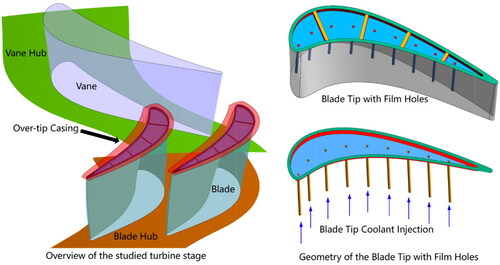
Table 1. Geometric and flow conditions.
2.2. Meshing and solver description
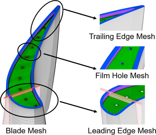
The commercial software ANSYS ICEMCFD is applied to produce the structured hexahedral mesh for the simulation including one stator vane and one rotor blade with 1.2 × 10⁶ nodes for the stator vane domain and 5.6 × 10⁶ nodes for the rotor blade domain. Moreover, more than130 layers of grids are defined along the span-wise direction involving 50 nodes inserted within the tip clearance. The present research aims to clarify the mechanism inside the tip clearance with small space. To the end, the first cell thickness adjacent to the blade wall surface is refined to ensure y+ < 1.0 to meet the requirement of the turbulence model. illustrates the blade mesh in the present study.
Figure 2. Overview of the structured mesh for the cavity tip.
ANSYS-CFX is used and the Three-dimensional (3-D) Reynolds-Averaged Navier–Stokes (RANS) equations were solved. The governing equations of continuity, energy, and momentum are discretized in time for steady calculations. The element-based finite volume method is adopted in ANSYS CFX for the spatial discretization of the governing equations. The second order advection scheme is implemented. The details of the computational approaches in the current research are presented in .
Table 2. Numerical method.
2.3. Turbulence model and experimental validation
The current section is for the purpose of choosing the optimal turbulence model for the numerical simulations. Tturbulence model is selected for closure of the Three-dimensional (3-D) Reynolds-Averaged Navier–Stokes (RANS) equations. Hence, it is of great significance in a numerical simulation by using the RANS method. The CFD method is firstly validated in this study. The simulated blade tip heat transfer distributions with four different typical turbulence models were compared with experimental results [Citation10]. gives the comparisons in detail. The heat transfer coefficient is defined as.
(1)
(1)
where
is the heat flux of the blade tip wall surface. T∞ and
are the mainstream temperature and wall surface temperature, respectively.
Figure 3. Validation of the numerical method.
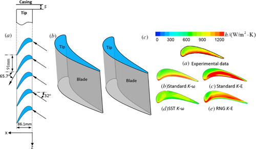
states that the k − ω turbulence model attains the best accuracy among four investigated turbulence models in terms of the blade tip heat transfer coefficient. The comparison indicates that the k − ω turbulence model can obtain more details of the flow and temperature distribution adjacent to the blade tip. Consequently, the k − ω turbulence model as closure equations is chosen for the numerical simulations.
2.4. Mesh convergence study
An appropriate number of nodes is selected for the numerical simulations according to the time consuming and computing resource. The factor along three dimensions was changed to compare the numerical results with the experimental data. The mesh convergence study reveals that the 1.2 × 10⁶ mesh nodes for the stator vane domain and 5.6 × 10⁶ for the blade domain are sufficient in the simulations.
3. Multicavity tip coolant injection design
3.1. Multicavity tip design
The focus of the current investigation is the film cooling of the cavity blade tip. Therefore, the blade tip design is illustrated. The blade tip with single cavity is presented in . d and s are the cavity tip depth and the tip clearance, respectively. The cavity depth is set as a constant for all numerical simulations.
is the height of the blade. Five cavity tips are listed in . Ribs are inserted inside the cavity, forming the labyrinth seal along the chamber line. Furthermore, each of the ribs is perpendicular to the blade tip cavity chamber line. The rib width and height are equal to the width of the squealer rim and cavity depth, respectively. That means the introduction of rib will not change the height of the blade in radius direction.
Figure 4. Cavity tip definition.
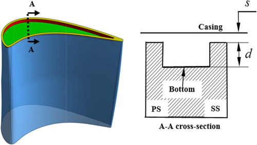
Figure 5. Definition of the multicavity tip.
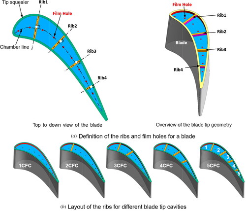
3.2. Tip coolant injection layout
This research investigates the film cooling performance of the cavity tip. The film holes are equally spaced at the chamber line of the blade tip. Therefore, the ribs divide the film holes coolant injection into different cavities. The nomenclature of the cases is defined based on the number of cavities. The blade with a single tip cavity film cooling is named as 1CFC, and the case with five tip cavities is defined as 5CFC. Overall, this study aims to reveal the influence of the spilt ribs on the blade tip film cooling performance.
4. Results and discussion
4.1. Tip film-cooling results
For film cooling, the film cooling effectiveness is mainly dominated and driven by aerodynamics. A variation in film cooling effectiveness should be an indicator related to the change in aerodynamics. Therefore, in the present study, the aerodynamic characteristics is characterized by the film cooling effectiveness which calculated via EquationEq. (2)(2)
(2) :
(2)
(2)
where
is the adiabatic temperature for the blade tip.
and
refer the inlet mainstream temperature and the coolant temperature, respectively.
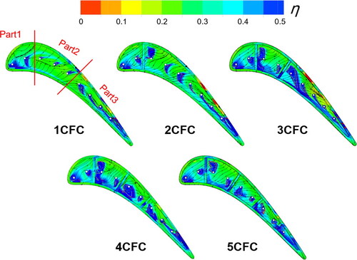
The details concerning the film cooling effectiveness and streamline are shown in . The dissimilarity between the film cooling effectiveness and streamline distribution on the different blade tip configurations is apparent. For 1CFC, the tip is dominated by large regions of low film cooling effectiveness. This result is due to coolant flowing vertically into the tip cavity is lifted off from the surface, especially Part 2. However, the salient features observed inside the cavity are twofold in the 1CFC, resulted in different film cooling coverage surrounding the film holes. At tip leading edge, the majority of incoming flow enters the Part 1 from the squealer rim along pressure side, which is conducive to increasing the area of high film cooling effectiveness. Near the rear part (Part 3), the leakage direction is obviously deviated to the mainstream. Here, the coolant is pushed toward the trailing edge inducing the presence of maximal film cooling coverage. Of other blade tip configurations studied, the introduction of ribs greatly changes the distribution of film cooling effectiveness. As to 2CFC, the most remarkable variation is the regions of high film cooling effectiveness downstream of rib1 are increased when compared to that of the 1CFC. Along with the increase in the number of ribs, the blade tip is divided into many smaller cavities. The coolant is limited in each small cavity owing to the blockage of ribs, corresponding to more coolant further reattaching to the tip surface. Conversely, each small cavity suppresses the coolant slipping off from the cavity surface to some extent. Thus the tip film cooling coverage augments with the increase of ribs. In addition, on the squealer rim along the suction side is there the removal of low film cooling coverage in the 3CFC and 4CFC.
Figure 6. Film cooling effectiveness and streamlines on blade tip.
Following discussion will be based on further quantitative analysis of the tip area-averaged film cooling effectiveness, EquationEq. (3)(3)
(3) , becomes:
(3)
(3)
where
is the total amount of the separate surface in the blade tip.
and
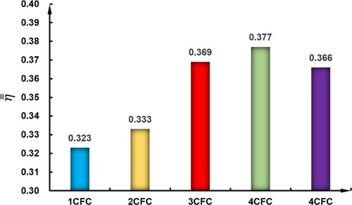
are area-averaged film cooling effectiveness and area for each separation surface. displays area-averaged film cooling effectiveness on the blade tip. Area-averaged film cooling effectiveness among the multicavity tip shows an increasing trend. The most marked observation is that the highest area-averaged film cooling effectiveness exists on the 4CFC, which is 14.3% higher than that for the 1CFC.
Figure 7. Area-averaged film cooling effectiveness on blade tip.
illustrates the overall flow pattern and total temperature near the blade tip gap. The coolant and incoming flow are denoted by the blue streamlines and black streamlines, respectively. Nine cut planes are colored by total temperature, which are arranged at equally spaced and perpendicular to the camber line. As for the 1CFC, the trajectory of leading-edge streamlines indicates that the incoming flow through the squealer rim impacts and rolls around inside the tip cavity, resulting in the generation of the cavity vortex (CV). This vortex is curled downstream toward the tailing edge, where the flow from the pressure side, the coolant of Part 1 and Part 3 (see 1CFC in ) are involved. The adverse consequence is that the coolant located at Part 2 cannot remain attached, and its film cooling coverage is far lower relative to Part 1 and Part 3. These agree well with the result as shown in . Conversely, the regions with cavity vortex have low value of total temperature, depending on the addition of coolant. And similarly, the coolant passing over the tip gap is mixed with the tip leakage vortex (TPL), which help cool the suction side surface. Hence, the total temperature here is relatively small (see cut planes in ).
Figure 8. Flow structure and total temperature near the blade tip clearance.
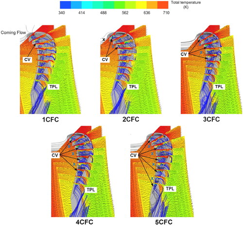
In terms of other blade tip configurations, adopting the ribs has enhanced the tip flow complexity. The fluid (black cross mark) at the frontal part of 2CFC, , rolls up into the cavity vortex. Subsequently, the vortex is truncated by the rib1, which is prevented from entraining the incoming flow (blue cross mark) entering the rear part. Therefore, the new cavity vortex is generated and fully developed in the rear cavity. The vortex and rib have a significant effect on the attachment of coolant. The partial coolant is trapped inside the frontal cavity and tend to cover a wider area of the blade tip. Besides, another partial cooland passes over rib1 and meets with the vortex of rear cavity, further enlarging its core. Here the film cooling effectiveness is increased (see ).
With more ribs being implemented inside the tip cavity, the blade tip consists of several small tip cavities. There is a portion of incoming flow (see the blue cross mark in ) in each cavity, which cannot be sucked by the vortex upstreams of the frontal cavity under the truncation of ribs and interacts with the coolant to form a new cavity vortex. Theses vortices can be effective in promoting the coolant to cool the tip surface better (see ). In addition, the flow choking does exist in the coolant caused by the ribs. As a result, for other blade tip configurations, total temperature near the suction side is higher in comparison with 1CFC.
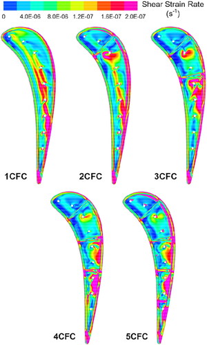
To further reveal the interaction between the incoming flow and coolant, displays the distribution of shear strain rate on the blade tip. Generally, areas of high shear strain rate or shear stress are typically areas where the highest mixing occurs. It can be observed that the high shear strain rate in 1CFC is near the film holes, corresponding to the vortex shown in . However, the shear strain rate shows a relatively low level at the tip leading edge. This is because the vortex first generated here is less mixed with the coolant, and its intensity is low. With the development of vortex, there is a strong shear between incoming flow and coolant, leading to a region of high shear strain rate in the direction of trailing edge. Furthermore, when the fluid flows out of the tip gap, the high level of shear strain rate is located where the flow accelerates past the squealer rim along the suction side in 1CFC. In multicavity tip, the flow pattern inside the rear cavity is affected by the fluid of frontal cavity. The resulting shear strain rate is higher than that of the frontal cavity. Additionally, the ribs may be beneficial in blocking the tip leakage flow, causing the reduction of high shear strain rate region in the 4CFC and 5CFC.
Figure 9. Distribution of shear strain rate on the blade tip.
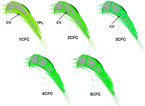
The 3-D core regions of the vortices are presented in . The Q-criterion is selected as the method to visualize these flows. The difference in these tips is the influence of ribs on vortex core. When the rear cavity is big enough (2CFC and 3CFC), the vortex core is apparently existed and is drawn downstream toward the trailing edge for a shorter distance when compared to the 1CFC. There is no shaped vortex core in the 4CFC and 5CFC with the increase in quantity of tip cavities. As previously stated, the coolant is hardly attached to the blade tip surface due to the full development of vortex from the tip leading edge to trailing edge. The trend is the reverse of that for the scattered vortex core. Therefore, the multicavity tip with three cavities or more produces wider film cooling coverage ().
Figure 10. Vortex structure inside the tip cavity visualized by the Q-criterion.
4.2. Over-tip casing film cooling results
As illustrated above, in the multicavity tip, the application of ribs causes remarkable alternation in the distribution of the tip film cooling effectiveness and the flow structure inside the cavity. Consequently, the relevant aerothermal performance of the over-tip casing is also varied greatly. In this section, the film cooling effectiveness regarding the over-tip casing is investigated in . The salient flow features in 1CFC are no coolant acts on the frontal part of over-tip casing and the regions corresponding to the tip squealer rim. These are caused by the axial pressure difference (from the tip leading edge to trailing edge direction) and the lateral pressure difference (between the pressure side and suction side). Both subsequently make it difficult for the coolant to attach the over-tip casing surface. And similarly, the regions of the over-tip casing corresponding to the tip squealer rim indicate the minimal tip gap height, inducing no film cooling efficiency here. In terms of a region with high film cooling efficiency, which owing to the impingement of leakage flow with coolant.
Figure 11. Film cooling effectiveness and streamlines on over-tip casing.
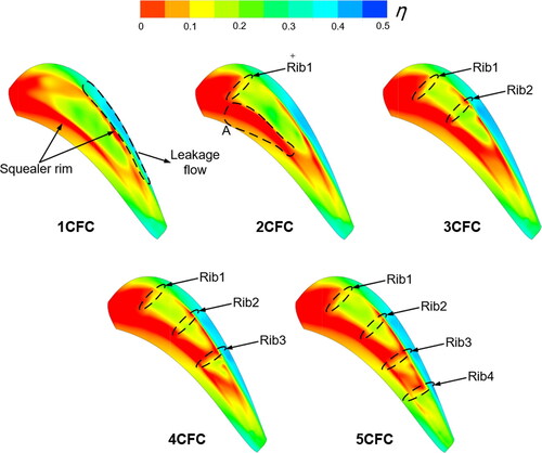
As with the case for Rib1 inside the tip cavity (see 2CFC in ), the area without film cooling efficiency on the frontal part of over-tip casing decreased, whereas the trend is almost opposite for the rear part of casing. Besides, the region (marked A) without film cooling coverage shows an increasing trend in comparison with 1CFC. This can be explained by that a large part of the coolant is confined in the cavity by vortices and rib1, indicating that it is not conducive to cooling the over-tip casing. Of other blade tip configurations considered, the distribution of film cooling efficiency basically shows agreement with the 2CFC. However, the increase in regions with no film cooling efficiency is occurred surrounding the Rib3 and Rib4 (see 4CFC or 5CFC in ), proving that the smaller cavity at tip trailing edge cannot be beneficial in cooling the casing compared with 1CFC.
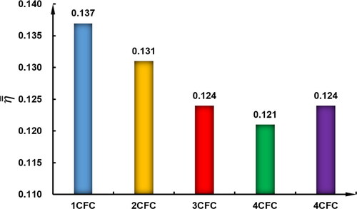
presents area-averaged film cooling effectiveness of the over-tip casing for different cases. The 1CFC obtains the largest area-averaged film cooling effectiveness on the over-tip casing. The over-tip casing in multicavity tip has a lower level of the film cooling effectiveness relative to the 1CFC. indicates that the minimal area-averaged film cooling effectiveness of 3CFC is 11.7% lower than that of the 1CFC. The data agree well with the results as depicted in .
Figure 12. Area-averaged film cooling effectiveness on over-tip casing.
5. Conclusions
A numerical study is employed to investigate the effects of the multicavity tip coolant injection on the blade tip and the over tip casing aerothermal performance in a high-pressure turbine cascade. The distributions of film cooling effectiveness on the tip surface and over-tip casing are quantitatively analyzed. The related aerothermal flow mechanism between the coming flow and coolant is further examined, analyzed, and discussed in the current study.
In the multicavity tip, the influence of the ribs inside the tip cavity is twofold: there is an increase in coolant trapped within each cavity and also a reduction in coolant shifted from the tip cavity. Hence, the ribs inside the multicavity tip have a higher improvement in film cooling coverage. The largest area-averaged film cooling effectiveness is obtained on the case with four tip cavities film cooling (4CFC), which is 14.3% higher than that of the 1CFC.
The augmentation in film cooling coverage can be explained by the vortex caused by the strong shear effect between the incoming flow and coolant. The coolant is involved into the vortex inside each little cavity and drawn toward surrounding the film holes, resulting in a wider film cooling coverage. Therefore, the vortex shows a superiority in promoting the coolant to cool the tip surface better.
Of all simulations studied, the trend of film cooling coverage on the over-tip casing is the reverse of that for the blade tip surface. This is because that the coolant is hardly attached to the over-tip casing surface corresponding to the tip squealer rim under the pressure difference. Furthermore, the regions between ribs and the over-tip casing meaning the minimal tip gap height, leading to acceleration of the flow here. As a result, the multicavity tip is not conducive to cooling the over-tip casing with coolant when compared to that of the blade with a single tip cavity film cooling (1CFC).
| Nomenclature | ||
| = | area | |
| = | heat flux | |
| T | = | temperature |
| = | mainstream temperature | |
| = | wall temperature | |
| = | wall adiabatic temperature | |
| = | coolant temperature | |
| y+ | = | dimensionless wall-normal height of first cell at a wall |
| Greek | = | |
| = | film cooling effectiveness | |
| = | area-averaged film cooling effectiveness | |
| Subscripts | = | |
| = | wall condition | |
| = | wall adiabatic condition | |
| = | mainstream condition | |
| = | coolant condition | |
Additional information
Funding
References
- R. S. Bunker, “A review of turbine blade tip heat transfer,” Ann. N. Y. Acad. Sci., vol. 934, pp. 64–79, 2001. DOI: 10.1111/j.1749-6632.2001.tb05843.x.
- J. D. Denton, “Loss mechanisms in turbomachines,” ASME J. Turbomach., vol. 115, no. 4, pp. 621–656, 1993. DOI: 10.1115/1.2929299.
- K. Du, L. Song, J. Li, and B. Sunden, “Effects of the layout of film holes near the vane leading edge on the endwall cooling and phantom cooling of the vane suction side surface,” Numer. Heat Transf. A: Appl., vol. 71, no. 9, pp. 910–927, 2017. DOI: 10.1080/10407782.2017.1326788.
- K. Du, Z. Li, J. Li, and B. Sunden, “Influence of the pressure side injection slot on the cooling performance of endwall surface,” Numer. Heat Transf. A: Appl., vol. 73, no. 8, pp. 517–534, 2018. DOI: 10.1080/10407782.2018.1459140.
- R. S. Bunker, “Axial turbine blade tips: Function, design, and durability,” AIAA J. Propuls. Power, vol. 22, no. 2, pp. 271–285, 2006. DOI: 10.2514/1.11818.
- B. Sunden and G. Xie, “Gas turbine blade tip heat transfer and cooling: A literature survey,” Heat Transf. Eng., vol. 31, no. 7, pp. 527–554, 2010. DOI: 10.1080/01457630903425320.
- N. L. Key and T. Arts, “Comparison of turbine tip leakage flow for flat tip and squealer tip geometries at high-speed conditions,” J. Turbomach., vol. 128, no. 2, pp. 213–249, 2006. DOI: 10.1115/1.2162183.
- J. S. Kwak et al., “Heat transfer coefficients on the squealer tip and near tip regions a gas turbine blade with single or double squealer,” J. Turbomach., vol. 125, no. 4, pp. 778–787, 2003. DOI: 10.1115/1.1626684.
- J. S. Kwak, J. Ahn, and J. C. Han, “Effects of rim location, rim height, and tip clearance on the tip and near tip region heat transfer of a gas turbine blade,” Int. J. Heat Mass Transf., vol. 47, no. 26, pp. 5651–5663, 2004. DOI: 10.1016/j.ijheatmasstransfer.2004.07.029.
- D. Yang and Z. Feng, “Tip leakage flow and heat transfer predictions for turbine blades,” ASME Turbo Expo 2007: Power for Land, Sea, and Air. Montreal, Canada: American Society of Mechanical Engineers, 2007, pp. 589–596. DOI: 10.1115/GT2007-27728.
- C. Zhou and H. Hodson, “Squealer geometry effects on aerothermal performance of tip-leakage flow of cavity tips,” J. Propuls. Power, vol. 28, no. 3, pp. 556–567, 2012. DOI: 10.2514/1.B34254.
- J. Li, K. Du, and L. Song, “Effects of tip cavity geometries on the aerothermal performance of the transonic turbine blade with cavity tip,” Proceedings of the Institution of Mechanical Engineers Part a Journal of Power & Energy, London, UK, 2016.
- N. Lamkin, A. Granovskiy, V. Belkanov, and J. Szwedowicz, “Effect of common blade tip squealer designs in terms of tip clearance loss control,” Proceedings of ASME 2013 Turbine Blade Tip Symposium & Course Week, TBTS2013-2040, Hamburg, Germany, 2013. DOI: 10.1115/TBTS2013-2040.
- J. S. Park, S. H. Lee, J. S. Kwak, W. S. Lee, and J. T. Chung, “Measurement of blade tip heat transfer and leakage flow in a turbine cascade with a multi-cavity squealer tip,” ASME Turbine Blade Tip Symposium, Hamburg, Germany, 2013. DOI: 10.1115/TBTS2013-2072.
- K. Du, Z. Li, J. Li, and B. Sunden, “Influences of a multi-cavity tip on the blade tip and the over tip casing aerothermal performance in a high-pressure turbine cascade,” Appl. Therm. Eng., vol. 147, pp. 347–360, 2019. DOI: 10.1016/j.applthermaleng.2018.10.093.
- V. Shyam and A. Ameri, “Comparison of various supersonic turbine tip designs to minimize aerodynamic loss and tip heating,” Vancouver, British Columbia, Canada, ASME, 2011. Paper No. GT2011-46390. DOI: 10.1115/GT2011-46390.
- Q. Zhang and L. He, “Tip-shaping for HP turbine blade aerothermal performance management,” J. Turbomach., vol. 135, no. 5, pp. 051025, 2013.
- C. Zhou, H. Hodson, I. Tibbott, and M. Stokes, “Effects of endwall motion on the aero-thermal performance of a winglet tip in a HP turbine,” J. Turbomach., vol. 134, no. 6, pp. 061036, 2012. DOI: 10.1115/1.4006302.
- A. K. Saha, S. Acharya, R. Bunker, and C. Prakash, “Blade tip leakage flow and heat transfer with pressure-side winglet,” Int. J. Rotating Mach., vol. 2006, pp. 1–15, 2006. DOI: 10.1155/IJRM/2006/17079.
- Z. Zou, F. Shao, Y. Li, W. Zhang, and A. Berglund, “Dominant flow structure in the squealer tip gap and its impact on turbine aerodynamic performance,” Energy, vol. 138, pp. 167–184, 2017. DOI: 10.1016/j.energy.2017.07.047.
- Z. Zou, L. Xuan, Y. Chen, and F. Shao, “Effects of flow structure on heat transfer of squealer tip in a turbine rotor blade,” Int. Commun. Heat Mass Transf., vol. 114, pp. 104588, 2020. DOI: 10.1016/j.icheatmasstransfer.2020.104588.
- K. Huang, J. Zhang, C. Wang, and S. Liu, “Large-eddy simulation of single-row serrated trenched-hole film cooling on turbine guide vane,” Int. Commun. Heat Mass Transf., pp. 1–23, 2022.
- R. J. Goldstein, “Film cooling,” Adv. Heat Transf., vol. 7, pp. 321–380, 1971.
- D. G. Bogard and K. A. Thole, “Gas turbine film cooling,” J. Propuls. Power, vol. 22, no. 2, pp. 249–270, 2006. DOI: 10.2514/1.18034.
- R. S. Bunker, “A review of shaped hole turbine film-cooling technology,” J. Heat Transfer Trans. ASME, vol. 127, no. 4, pp. 441–453, 2005. DOI: 10.1115/1.1860562.
- J. C. Han, S. Dutta, and S. V. Ekkad, Gas Turbine Heat Transfer and Cooling Technology, New York: Taylor & Francis, 2000.
- J. C. Han, “Advanced cooling in gas turbines - 2016 Max Jakob memorial award paper,” J. Heat Transf., vol. 140, no. 11, pp. 113001, 2018.
- J. S. Kwak and J. C. Han, “Heat transfer coefficient and film cooling effectiveness on the squealer tip of a gas turbine blade,” ASME J. Turbomach., vol. 125, no. 4, pp. 648–657, 2003. DOI: 10.1115/1.1622712.
- S. P. Mhetras, D. Narzary, Z. Gao, and J. C. Han, “Effect of a cutback squealer and cavity depth on film-cooling effectiveness on a gas turbine blade tip,” ASME J. Turbomach., vol. 130, no. 2, pp. 021002, 2008.