
 ?Mathematical formulae have been encoded as MathML and are displayed in this HTML version using MathJax in order to improve their display. Uncheck the box to turn MathJax off. This feature requires Javascript. Click on a formula to zoom.
ABSTRACT
Modern aircraft can be equipped with a flight envelope protection system: automation which modifies pilot control inputs to ensure that the aircraft remains within the allowable limits. Overruling the pilot inputs may lead to mode confusion, even when visual or auditory feedback is provided to alert pilots. We advocate using active control devices to make the flight envelope protection system tangible to the pilot. This paper presents the main findings of an evaluation of three haptic feedback designs for flight envelope protection. The first concept used both force feedback and vibro-tactile alerts, producing promising, yet inconclusive, results. The second concept used asymmetric vibrations to give directional alerting cues, which did not result in improved performance on initial use, but which did yield improved learning rate for the task. The third system employed force feedback to physically guide the pilot away from flight envelope limits, which yielded safety improvements from the first use, but created dependence: pilot performance degraded immediately after the force feedback was removed. From this, we advise to use asymmetric vibrations during training for flight envelope excursions, to leverage active control interfaces for providing force feedback during operation, and reevaluate a combination of both to combine their advantages for single-pilot operations.
1. Introduction
Both international aviation safety boards, such as the European Union Aviation Safety Agency EASA, and airline associations, for example, the International Air Transport Association IATA, identify loss of control in flight as one of the key risk areas resulting in most fatalities within aviation. (EASA, Citation2019; IATA, Citation2018) A safety issue contributing to such a loss of control is identified as the inadequate monitoring of the main flight parameters and automation modes. To ensure and improve current safety levels, these loss of control events should be prevented.
Lack of automation mode awareness was a contributing factor for the Air France 447 accident in which the aircraft reverted to a less stringent protection system due to a sensor failure. Surprised by the high altitude dynamics of the Airbus A330 aircraft and confused about the active flight envelope protection modes, the pilots incorrectly assessed that they were in a high speed situation and pulled back on the side stick, not realizing that this placed them into a stall which was only communicated to the pilots with an aural warning, initially masked by a master caution warning. The accident report indicates that this aural warning should be complemented which would provide the crew with additional information to enable them to escape from an erroneous understanding of the situation (Bureau d’Enquêtes et d’Analyses pour la sécurité de l’aviation Civile, Citation2012). In another case, Air Asia 8501, the Airbus A320 rudder limiter malfunction and subsequent actions of the pilots resulted in a degraded protection mode which disengaged the autopilot. It took the pilots nine seconds before a correcting action was inputted, in which time the aircraft had reached a bank of 54. Their lack of actions resulted in extreme bank angles and a prolonged stall. Unfortunately, this flight also crashed, causing loss of all crew and passengers (Komite Nasional Keselamatan Transportasi, Citation2015). If the pilots are informed about the approach to the limits during the initial moments, similar accidents can be avoided. Both aircraft, the A330 and A320, have a computerized system providing flight envelope protection, and a passive control device.
These examples show that loss of control occurrences can be expected to reduce by improving the information presented to pilots. This can be achieved by augmenting the visual displays in the cockpit with information on the limits of the aircraft, i.e., the flight envelope. Research showed that this can improve safety by reducing the risk of violations of those limits (Ackerman et al., Citation2017). Once the limits are exceeded, for example, in a stall, the information on the pfd can be augmented with recovery guidance which delivers recovery performance improvements, as shown in three simulator evaluations (Schuet et al., Citation2019).
Apart from the visual channel, pilots can also perceive information through the sense of touch. In conventional aircraft, often flight controls with a mechanical link are present, i.e., there is a hard link from the control surfaces to the control device by, for example, a combination of cables and pulleys. Any limit imposed by the flight envelope protection can be observed by the pilot by feeling what the controls are doing, i.e., by the haptic feedback present in the control device. A typical example with extreme effect is a stick-pusher as present in some high-tail configuration aircraft such as the Lockheed F-104 Starfighter, which provides a strong stick-forward force for high pitch rates and angles of attack, resulting in a nose-down input and protecting the aircraft from stalling, with actions that are eminently noticeable for the pilot (Cook, Citation1965).
With the advent of fly-by-wire systems, the physical link between the control device and control surfaces is lost. Sensors register the control device state, and using electrical wires the pilot intent is communicated to the computer, creating a unidirectional flow of information. Therefore, the information on the flight envelope protection system is not transferred to the pilot using the sense of touch. Literature on the physical/haptical connection between both pilots (Field & Harris, Citation1998; Uehara & Niedermeier, Citation2013; Wolfert et al., Citation2019), and the crashes of Air France 447 and Air Asia 8501, show that not having this direct way of feedback might contribute to a reduced awareness of the pilot on the state of the aircraft, especially when sensor failures occur and the system reverts to less protected regimes.
A reason this haptic information was not fully integrated after the introduction of fly-by-wire systems, is the complexity of the devices required to implement the forces. This used to be an issue because of size, power, and stability requirements. Nowadays, low-weight reliable force feedback for control devices offers the possibility to re-introduce haptic feedback in the fly-by-wire control systems (Warwick, Citation2015). Such an active control device can be used to reduce the occurrences of pilot-induced oscillations by changing the control device gain (Klyde et al., Citation2011). Both a passive spring or an active counter-force were investigated to communicate the distance to the flight envelope limits. The latter gave best tracking performance increase compared to the baseline condition (Schmidt-Skipiol & Hecker, Citation2015). Another example uses the active control device to show a set of predicted controllability limits, which was shown to be used by pilots in an experiment (Stepanyan et al., Citation2017). The relative distance of the aircraft state to the limits can also be presented using vibrations on the pedals and a sliding element on the stick and the evaluation showed promising, positive results (Zikmund et al., Citation2020).
Since current control devices have the possibility to re-introduce haptic feedback on the modern flight deck, and it has been shown to be an effective way to provide pilots with direct information, we investigated whether this type of feedback can be used to improve pilot awareness of the flight envelope protection system. This paper presents the design and evaluation of three concepts for haptic feedback on the flight envelope protection system which can be applied to any fly-by-wire control system. To this end, we explored the effects of introducing various types of haptic support on the interaction of an aircraft, in our case on a (simulated) A320 aircraft.
First, Section 2 introduces the flight envelope protection system which is communicated to the pilot. Next, three different designs and their evaluations are discussed in consecutive sections. Recommendations and our view on the next steps in haptic feedback for flight envelope protection are discussed in Section 6. Finally, conclusions are shown in Section 7.
2. Flight envelope protection
One aircraft model was available for the evaluations of the haptic feedback designs: an aircraft model with Airbus A320-like dynamics and control laws (Lombaerts et al., Citation2016). As such, this section summarizes the main working principles of such an aircraft.
Modern-day Airbus aircraft, like the A320 and the A330, employ a fly-by-wire system. This means that there is no physical connection between the control surfaces and the control device. The latter acts as an interface for the pilot to provide inputs to the flight control computers which then command the control surfaces with hydraulic actuators. This allows a flight envelope protection system to be used, which can check and, if necessary, limit the pilot inputs, this to ensure that no limits are violated.
Longitudinal control in a fly-by-wire Airbus, with all sensors functional (the “normal law” control law), is provided using -control, which is a combination of both pitch rate (q) and load factor (n) (Airbus, Citation2003; Chatrenet, Citation1995; Favre, Citation1994; Niedermeier & Lambregts, Citation2012). On top of this control law, a hard envelope limit is employed, which prevents the pilot from exceeding limits on angle of attack (
), load factor (
), and maximum velocity (
). This protection is depicted in , where the nominal flight envelope is the extreme limit which can not be exceeded, the safe flight envelope is the point where protections start acting. The envelope is constructed by the maximum (
) and minimum (
) load factor, their protection limits (
and
, respectively), the maximum operation velocity (
, and protection
), and minimum velocity (
, and protection
).
Figure 1. Flight envelope, velocity (V) versus load factor (n)
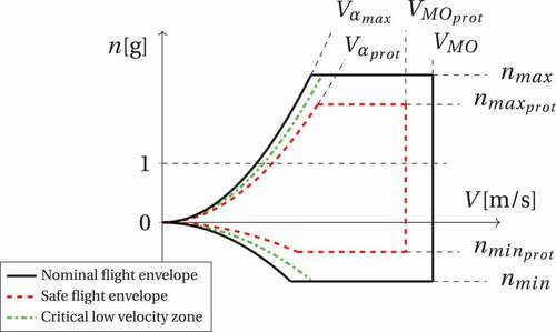
When a flight control computer fails, or when a sensor failure occurs, the control law is reverted to a degraded mode. In this research, we will consider the Airbus “alternate law without reduced protections”, where the same protections apply as before, only the angle of attack protection is lost. Hence, in alternate law the aircraft can be stalled, and it allows pilots more extreme control actions.
This approach of flight envelope protection results in mixed-input shared control, sometimes called blended shared control or parallel autonomy: the pilot and the automation are sharing control of the aircraft and their intentions are mixed when they are inputted to the flight control computers. However, this mixing happens ‘under the hood’ and the control interventions of the automation are not fed back to the pilot. Therefore, the pilot’s internal mapping between control inputs and aircraft state may be distorted, which might result in issues with situation awareness and mode awareness (Abbink et al., Citation2012). This might have contributed to accidents where pilots were not aware of what control law was active, and what protections were still active. As such, a clear and intuitive way of presenting this information can be found in haptic feedback, and three designs with corresponding evaluations are presented in the following.
3. Guidance and discrete feedback
Exploratory research first investigated a system which provided a change in force gradient near the flight envelope limits, and pilots indicated that it lacked discrete information, a ‘tick-on-the-stick’, indicating when the protections become active (Lombaerts et al., Citation2017). Therefore, the first design iteration involved both guidance and discrete haptic feedback (Van Baelen et al., Citation2020). Although one should ideally feel haptic feedback, the working principles are visualized in this paper using the haptic profile, i.e., the amount of force required on the side stick, to move that side stick to a certain deflection. In most applications, as in an Airbus A320, this is a constant, piece-wise linear relationship as can be seen in .
Figure 2. Haptic profile: force required on the side stick versus deflection
The goal of the haptic feedback is to communicate the flight envelope protection limits in an intuitive way using the following five cues:
When the aircraft leaves the safe flight envelope (anywhere outside the red dashed line in ), a discrete, unit pulse forcing function is added to the stick force, which is perceived as a ‘tick on the stick’. This is illustrated on the haptic profile with the inset graph in .
For aircraft velocities close to the lower velocity limit
, a stick shaker (in the form of a sinusoidal forcing function) activates, to communicate the increasing risk of stalling the aircraft.
To communicate the relative distance to the limit, the spring coefficient increases when moving from the safe flight envelope to the actual limit (the black line on ). The increased spring coefficient results in a situation where pilots must apply a larger force to move the stick in a particular direction, illustrated for positive (push) deflections in .
When the aircraft has a critically low velocity, and bringing the stick back to its neutral position is not sufficient to return to the safe flight envelope, the required stick deflection is communicated to the pilot by a change in neutral point of the stick, as illustrated in .
During an overspeed situation, the automatic ‘pitch up’ command is communicated to the pilot by a change in neutral point of the stick, similar to , but now using a negative neutral point position. This command is defined by one tuning parameter (
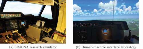
To evaluate this design, an experiment involving eleven Airbus pilots was conducted in the SIMONA research simulator, see (Van Baelen et al., Citation2020). It is a simulator with a full-fledged flight deck shell, over 180 degrees outside visual, a side stick on the right, rudder pedals in front, and throttle lever and flap levers to the left. Pilots were asked to manually fly two different approaches: a visual approach with elevated workload due to the procedure, and an instrument approach without outside visibility. During the visual approach, they encountered a windshear which required them to operate the aircraft move close to its limits during the recovery. In the instrument approach, ice was building on the aircraft wings, deteriorating the aerodynamic properties and resulting in the aircraft limits nearing the current state. The windshear scenario was flown in both the normal and alternate control law discussed above, the icing scenario was only flown using the alternate control due to limitations of the simulation. All pilots flew the three resulting scenarios with and without the haptic feedback system in a randomized Latin-square order.
Figure 3. Simulators used in the evaluations
We expected the haptic feedback to have an influence on performance, safety, workload, and pilot situation awareness. Performance was defined as the altitude lost during the windshear recovery, where less is better, or the deviation from the indented flight path during the instrument approach. Pilots were considered to be safe when margin was kept from the flight envelope limits, this was measured by the absolute distance from the aircraft state to the limit, the time pilots flew close to the limit, and the integral of the state above the flight envelope protection limit. The latter is a combination of both time and distance over the limit. Workload was measured using a Rating Scale Mental Effort (RSME) (Zijlstra, Citation1993), whereas subjective situation awareness was measured by asking the pilot whether (s)he was in control, and whether (s)he was missing information, ideally, a pilot is in full control and misses no information. For the experiment, it was hypothesized that the haptic feedback system supports pilots in their manual flying task, and therefore improve performance, increase safety, reduce workload, and improve situation awareness. Furthermore, we provided pilots with a debriefing questionnaire of 20 questions to query their experience with the haptic feedback and simulation environment. Statistical analysis was performed using a Wilcoxon test for questionnaires, ANOVA for ratio data, with a significance level of .
Results showed no significant changes in performance, safety margins, nor workload for any of the conditions or control laws used. Nevertheless, the haptic feedback did not hinder pilots in performing their tasks either. The debriefing illustrated that pilots experienced an increased situation awareness and see a clear potential benefit of implementing the haptic feedback system on a modern fly-by-wire flight deck. In conclusion, although most trends were positive, the experiment did not provide conclusive evidence of improved pilot situation awareness.
This conclusion corroborates with the systems evaluated in literature: multiple haptic concepts show great potential, yet lack clear conclusive evidence. This was found for the evaluation of system which changes the reference point of the control input, and limits the deflection based on the remaining control space (Stepanyan et al., Citation2017), as well as the starting point of this research (Lombaerts et al., Citation2017). The evaluation of an increased resistance near the flight envelope edges did show more conclusive results, although it used several non-pilots in the evaluation which renders the results less convincing (Schmidt-Skipiol & Hecker, Citation2015).
A probable reason for the lack of conclusive evidence for the results, and possibly for the evaluation in literature, is the low number of experiment participants due to the limited availability of professional pilots, the natural tendency of pilots to stay away from the limits, and the difference in behavior of multiple pilots.
4. Asymmetric vibrations
The debriefing of the first design iteration showed that the vibro-tactile cue, the ‘tick-on-the-stick’, was particularly well received by the participating pilots. Additionally, implementing a system with only a discrete cue was considered as less intrusive and more feasible for a retro-fit on current aircraft with passive side sticks. Therefore, the second design for haptic feedback employed only vibro-tactile cues. Despite pilot preference, the direction of the vibro-tactile cue was not always clear and warranted an improvement.
First, an experiment was performed in the perceivability of direction and activation of such vibrations (Van Baelen et al., Citation2020a). Results showed that a sawtooth-shaped vibration had a lower threshold compared to a triangular shape. At the threshold, participants are just able to tell that a cue was provided and indicate the correct direction of the cue. Therefore, the sawtooth-shaped vibration was recommended for implementation as a cue to alert pilots.
This sawtooth-shaped vibration was included in the haptic feedback system to inform pilots on an approaching flight envelope protection as well as on the direction of the corrective action (Van Baelen et al., Citation2019):
When the aircraft state leaves the safe flight envelope, i.e., crosses the red line on : a sawtooth-shaped forcing function is activated.
As long at the aircraft state remains outside the safe flight envelope: one sawtooth-shaped ‘tick’ is provided every second, where the intensity of the tick is linearly increasing with the magnitude of the safe flight envelope excursion, up to a maximum of twice the default magnitude.
When the velocity drops below
The resulting system remained a mixed-input shared control since the automation were not fed through the control device, the pilot was only informed on the state.
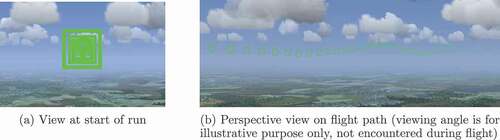
This system was evaluated by 24 pilots who held a current Private Pilot License (PPL) or Light Aeroplane License (LAPL) in the Human-Machine Interface laboratory, a fixed base simulator. shows this simulator which has an almost 180 degrees outside view, presents the instruments on a screen in front of the pilot, has a throttle quadrant at the left, and a custom hydraulically operated side stick at the right. In this simulator, the pilots flew a challenging vertical profile shown in , which was presented on the outside visual as illustrated by . To reduce variability in the results, each run was started with the automation controlling the engine at a fixed velocity. At one of the critical points in the run, a windshear was triggered and pilots had to manually recover from this situation by flying close to the flight envelope limits. Each pilot flew two blocks of four runs each, where the haptic feedback was enabled in one block, disabled in the other. Pilots were divided in two groups (each 12 pilots) with different order of enabling the haptic feedback to counterbalance the experiment. Obtained metrics contain those described with the previous design, as well as a validated acceptance scale (Van Der Laan-questionnaire). (Van Der Laan et al., Citation1997)
Figure 4. Flight path side-view, solid black vertical lines indicate “fly-through gates” shown on the outside visual; the thick red line indicates the trigger point of the windshear (not shown on the outside visual); the dotted blue lines indicate the windshear section used in our evaluation
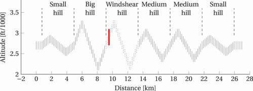
Figure 5. Example of the outside visual flight path visualization
From the obtained data, performance and safety metrics were calculated, and the averaged values over one block of four runs were compared. Statistical analysis was performed using a Wilcoxon with a significance level of . It was hypothesized that enabling haptic feedback would result in improved performance and safety. However, results did not show this expected change: performance (without haptics
,
; with haptics
,
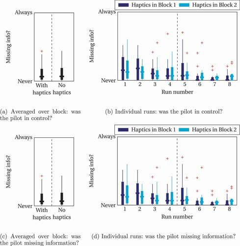
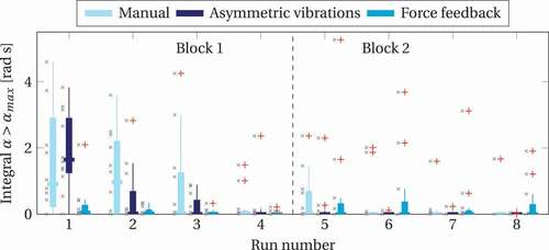
) and safety () metrics were unchanged when switching the haptic feedback. To exemplify this, a measure of safety during the windshear recovery is examined: the integral of the angle of attack above the limit value, i.e., a combination of the duration and magnitude of the limit excursion, for which the averaged values over one block of four runs is shown on and values closer to zero indicate improved safety. The figure shows that there is no change between both conditions: the medians are within the quartile distance, and no statistical difference is obtained. Similar observations are made for other safety and performance metrics. Workload and situation awareness are shown in, respectively, and , which show no significant differences when switching haptics, nor between runs. The lack of differences in metrics could be contributed to an order effect: the first four runs caused such a strong learning effect that this order effect rendered the comparison invalid.
Figure 6. Integral of angle of attack above maximum value during windshear recovery for the concept with asymmetric vibrations, x’s indicate individual data points, summarized data is presented using box-plots where outliers are represented by red pluses, retrieved from Van Baelen et al. (Citation2020b)
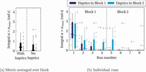
Figure 7. RSME for the concept with asymmetric vibrations, x’s indicate individual data points, summarized data is presented using box-plots where outliers are represented by red pluses, retrieved from Van Baelen et al. (Citation2020b)
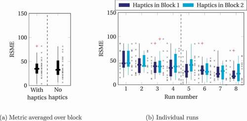
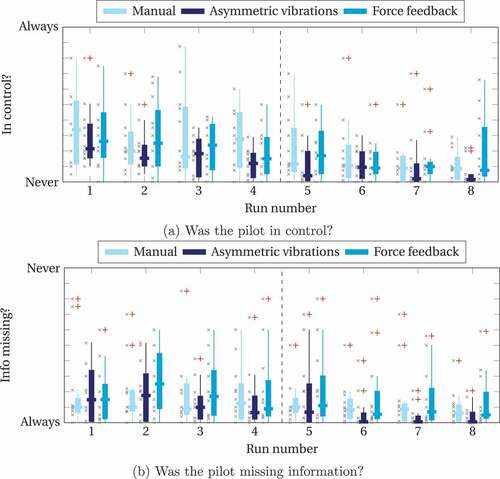
Figure 8. Situation awareness questions for the concept evaluation with asymmetric vibrations, x’s indicate individual data points, summarized data is presented using box-plots where outliers are represented by red pluses, retrieved from Van Baelen et al. (Citation2020b)
The results also indicated, however, that enabling the haptic feedback appeared to improve the learning rate after the first run, and that no after-effects were present when the feedback is removed. This is exemplified by the safety metric per run shown in , where the two groups are separated. Although both groups seem to start at a similar safety level, the group which received haptic feedback in the first block of four runs, and none in the second block, seems to improve its safety level more quickly compared to the group who did not receive haptic feedback in the first block. When this second group is provided with haptic feedback in Run 5, the safety level seems to improve greatly to Run 6. Although this trend is visible on the graph, it was not confirmed by statistical analysis. As such, besides the fact that most pilots were positive about the system and indicated that they expect it to improve safety, the results suggest a potential training benefit. Such an effect could only be possible if some useful information is provided by the haptic feedback system, and therefore it does improve situation awareness. The training benefit makes the cueing design a possible addition to a flight simulator training device in order to enhance learning. Vibro-tactile cues in the form of asymmetric vibrations are used in domains other then aerospace, for example, in automotive to indicate an imminent lane departure (Huang et al., Citation2015; Navarro et al., Citation2010; Wan & Wu, Citation2018). The sawtooth-shaped asymmetric vibration used in our application proved to be more powerful in communicating the direction of the cue. It is therefore recommended to use this cue in other applications, like automotive, to improve haptic communication.
5. Force feedback based on haptic shared control
Pilots undergo a rigorous training in order to obtain their license, including emergency scenario training. Nevertheless, training is never an exact replica of an emergency encountered in a real operation. A haptic feedback system should therefore, ideally, support pilots from their very first encounter with a flight envelope protection. Since the design using asymmetric vibrations was not able to do so, a design update is made based on haptic feedback design principles found in literature (Klyde et al., Citation2011; Kuiper et al., Citation2016; van Paassen et al., Citation2017).
The third iteration of our haptic feedback design used two cues to provide pilots with information on the flight envelope protection system: (i) changing the stiffness for an unwanted deflection as on , and (ii) actively moving the side stick to the required input to deactivate the flight envelope protection illustrated by (Van Baelen et al., Citation2021). Therefore, it is haptically guiding the pilot near the limits, i.e., haptic shared control, which is considered more effective in vehicle automation. (Abbink et al., Citation2018; Biondi et al., Citation2019)
It was evaluated in a similar setup as the previous design using runs where pilots followed a trajectory shown on the outside visual during which a windshear was encountered. In the first set of four runs, one group (of twelve pilots) received the guidance haptic feedback, one manual group did not receive any haptic feedback at all. Next, a second set of four runs was flown where all groups performed the task without haptic feedback.
As for the previous experiments, performance and safety metrics were calculated from the obtained data, and pilots were presented with questionnaires to query their experience. Statistical analysis was again performed using a Wilcoxon with a significance level of . It was hypothesized that the manual group would not improve performance to the level obtained with the asymmetric vibrations provide in the previous experiment, and that the force feedback is able to provide the pilots with support from the first use, without having large effects on workload or subjective situation awareness.
Figure 9. RSME for the concept evaluation with force feedback, x’s indicate individual data points, summarized data is presented using box-plots where outliers are represented by red pluses, retrieved from Van Baelen et al. (Citation2021)
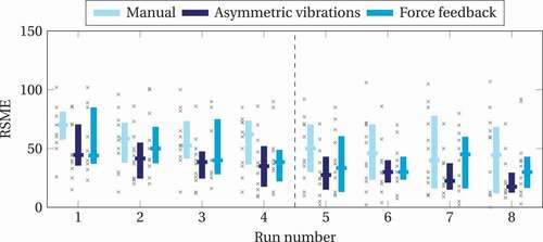
Figure 10. Situation awareness questions for the concept evaluation with force feedback, x’s indicate individual data points, summarized data is presented using box-plots where outliers are represented by red pluses, retrieved from Van Baelen et al. (Citation2021)
Results showed no significant changed in workload and situation awareness, respectively, and . At the first run, performance (manual ,
; asymmetric vibrations
,
; force feedback
,
), and safety metrics seem to follow the hypotheses. To exemplify the latter, the integral of angle of attack above the limit is shown in and shows significant differences between groups at the first run (
,
): post-hoc tests indicate near significance between the group receiving no feedback and the group receiving force feedback (
), and the group receiving force feedback has considerably safer, i.e., lower values from the start, compared to the group receiving cueing feedback (
). Additionally, it shows that the manual group eventually did obtain a safety level similar to the other groups. Since the haptic system supports from the very first use, it has to transfer information to the pilot and therefore, implicitly, improve pilot situation awareness. The concept is, however, sensitive to an after-effect: it creates a reliance of the pilot on the system as indicated by the spread of both the objective metrics shown in , and pilots commenting that information is missing when the haptic feedback is no longer supplied. This indicates that this last design can be useful to be implemented on the control device of an aircraft, as long as the support is always provided.
Figure 11. Integral above angle of attack limit during windshear (Manual Participant 7, , not shown) for the concept evaluation with force feedback, x’s indicate individual data points, summarized data is presented using box-plots where outliers are represented by red pluses, retrieved from Van Baelen et al. (Citation2021)
This conclusion is corroborated by literature on concepts which use force feedback to provide support from the first use, and is typically denoted as the “guidance hypothesis” (Schmidt et al., Citation1989). It was found in, for example, an abstract control task (Kuiper et al., Citation2016), and automotive examples (Petermeijer et al., Citation2015). Therefore, any application using force feedback should always provide the feedback, and should consider the implications when such feedback can no longer be supplied.
6. Recommendations
Based on the findings of the concept evaluations a number of general design recommendations can be given. In addition, some avenues for future research in haptic feedback support for envelope protection systems based on the limitations of the past research are stated as well.
6.1. Design guidelines
The designs presented in this paper used the two main types of haptic feedback: vibro-tactile and force feedback. The first concept, presented in Section 3, mixes both type of feedback: it uses both a ‘tick-on-the-stick’ to warn the pilot of the approaching limit, i.e., vibro-tactile feedback, and adjusted the stiffness to indicate the proximity, i.e., force feedback. The second design, presented in Section 4, involved only vibro-tactile cues in the form of asymmetric vibrations, and the last design, in Section 5, used pure force feedback by changing the stiffness and changing the neutral point.
Based on our results, we conclude with two main design guidelines:
Vibro-tactile cues can be used during training to inform the pilot of the flight envelope protection system.
It might improve learning rate, and it appears that such systems do not shown after-effects when support is removed.
Force feedback can be provided throughout the operation of the aircraft to inform the pilot of the flight envelope protection system.
It might support the pilot in staying within the flight envelope limits, yet is susceptible to performance degradation when removed.
6.2. Limitations and future research
Although our experiment was limited in several ways and the number of possible future research directions is very large, we will concentrate on the six main avenues in the following.
6.2.1. Flight envelope protection system
All haptic feedback concepts described in this paper used one flight envelope definition – limits on angle of attack, load factor, velocity, and bank limits – and protected these limits with one protection system based on the Airbus control laws. We expect that the haptic cues used in this paper can be extrapolated to other flight envelope definitions, yet this needs to be further investigated (Koolstra et al., Citation2012).
6.2.2. Startle by haptic feedback
In the evaluations performed in this thesis, the haptic feedback system was explained in detail to each participant and the participants were aware of possible emergency scenarios, reducing the risk of startle by the haptic feedback (Landman et al., Citation2017). Since warnings are known to be a possible source of startle (Belcastro & Foster, Citation2010; Kochan et al., Citation2004), it should be investigated whether the concepts presented in this paper prone to startle.
6.2.3. After-effects
The last two experiments used one repeated scenario, windshear, to look into a possible effect of the haptic feedback system when it is no longer provided, i.e., an after-effect. To further investigate the effect of the repeated scenario on the results and possible after-effects, an experiment which presents different scenarios to the pilots should be performed. Especially when the guidance hypothesis is confirmed for the final concept, mitigation of the degradation should be considered using possibly visual and/or aural indication to inform the pilot on the loss of haptic feedback.
6.2.4. Transfer-of-training
An important element in training is the transfer-of-training: a combination of how much knowledge obtained in the training is transferred to the targeted task, and whether that knowledge can be generalized (Reder & Klatzky, Citation1994). The former was evaluated when the haptic feedback was no longer provided in the second phase of the last two experiments. In order to evaluate the haptic feedback as a tool for training, generalization of knowledge should be investigated using a new scenario where the flight envelope protection system is activated, but due to a different emergency.
6.2.5. Single-pilot operations
Economic advantages of having fewer pilots are transitioning future flight decks from multi-pilot to single-pilot operations (Comerford et al., Citation2013), where a major hurdle is maintaining situation awareness of the pilot on all systems (Stimpson et al., Citation2016). The haptic feedback concepts presented in this paper have been shown to have a potential to improve pilot awareness of the flight envelope protection system, and should therefore be used in those single-pilot flight decks.
Additionally, haptic feedback has been used to support pilots in a path-following task, which could also be used to inform the pilot on the nominal autopilot control action to increase automation awareness (Olivari et al., Citation2014). When an emergency situation arises, a remote pilot can assist the on-board pilot (Comerford et al., Citation2013), where haptic feedback can be used to communicate control actions between pilots, for example, by linking the movements of the control devices such that each pilot can feel the control actions of the other, increase situation awareness of both pilots. However, it should be investigated whether haptic feedback for flight envelope protection can be combined with automation/remote pilot control input while keeping the source of the haptic feedback clear.
6.2.6. Variable g-loading environment
The design guidelines presented above result from experiments conducted in a non-moving simulator. This excludes the possible effects of variable g-loading environments on the results. Although literature shows that haptic feedback concepts can be transferred to variable g-loading environments (Klyde et al., Citation2014; Von Grünhagen et al., Citation2010), our design guidelines should be validated in a variable g-loading environment such as an experiment aircraft.
7. Conclusion
Modern aircraft can be supplemented with a flight envelope protection system: automation which reduces pilot control inputs to ensure that the aircraft remains within the allowable limits. With the introduction of fly-by-wire, the physical connection between the pilot and the control surfaces was lost, and the effects of the flight envelope protection system was not directly felt anymore by the pilot. Nowadays, active control devices allow the use of haptic feedback, i.e., through the sense of touch, to be re-introduced on the flight deck.
This paper reported on three designs, and evaluations, for such a haptic feedback system to communicate the flight envelope limits, and therefore the flight envelope protection activation. Each concept was shown to provide this information for a specific use-case: vibro-tactile feedback proved to be valuable during training, force guidance is valuable during continuous operation. Therefore, it is concluded that pilot situation awareness of the aircraft flight envelope protection system can indeed be improved using haptic feedback, and should be applied in future aircraft.
Additional information
Notes on contributors
Dirk Van Baelen
Dirk Van Baelen received the M.Sc. and Ph.D. degrees in Aerospace Engineering from TU Delft, the Netherlands, in 2016 and 2020, respectively, for his studies on the use of haptic feedback on modern flightdecks. He is currently working as a consultant, and remains interested in flight simulation and human-machine interfaces.
M. M. (René) van Paassen
M. M. (René) van Paassen received the M.Sc. and Ph.D. degrees in Aerospace Engineering from TU Delft, the Netherlands, in 1988 and 1994, respectively. He is currently an Associate Professor at the section Control and Simulation, Aerospace Engineering, TU Delft, working on human-machine interaction and aircraft simulation.
Joost Ellerbroek
Joost Ellerbroek received the M.Sc. and Ph.D. degrees in Aerospace Engineering from TU Delft, the Netherlands, in 2007 and 2013, respectively. He is currently an Assistant Professor at the section Control and Simulation, Aerospace Engineering, where his current work includes, amongst others, topics of airspace complexity and capacity analysis.
David A. Abbink
David A. Abbink received the M.Sc. and Ph.D. degrees in Mechanical Engineering from TU Delft, The Netherlands, in 2002 and 2006, respectively. He is currently a full Professor at the Cognitive Robotics Department, 3mE, TU Delft. His current research interests include shared control, neuromuscular behavior, driver support systems, and haptics.
Max Mulder
Max Mulder received the M.Sc. and Ph.D. degree (cum laude) in Aerospace Engineering from TU Delft, The Netherlands, in 1992 and 1999, respectively, for research on the cybernetics of tunnel-in-the-sky displays. He is currently Full Professor and Head of the section Control and Simulation, Faculty of Aerospace Engineering, TU Delft.
References
- Abbink, D. A., Carlson, T., Mulder, M., de Winter, J. C. F., Aminravan, F., Gibo, T. L., & Boer, E. R. (2018). A topology of shared control systems: Finding common ground in diversity. IEEE Transactions on Human-Machine Systems, 48(5), 509–525. https://doi.org/https://doi.org/10.1109/THMS.2018.2791570
- Abbink, D. A., Mulder, M., & Boer, E. R. (2012). Haptic shared control: Smoothly shifting control authority. Cognition, Technology and Work, 14(1), 19–28. https://doi.org/https://doi.org/10.1007/s10111-011-0192-5
- Ackerman, K. A., Talleur, D. A., Carbonari, R. S., Xargay, E., Seefeldt, B. D., Kirlik, A., … Trujillo, A. C. (2017). Automation situation awareness display for a flight envelope protection system. Journal of Guidance, Control, and Dynamics, 40(4), 964–980. https://doi.org/https://doi.org/10.2514/1.G000338
- Airbus. (2003). A319/A320/A321 Flight Crew Operating Manual (Tech. Rep. No. 36). Author.
- Belcastro, C. M., & Foster, J. V. (2010). Aircraft Loss-of-Control Accident Analysis. In Proceedings of the AIAA Guidance, Navigation, and Control Conference, Toronto (CA) (p. 39). https://doi.org/https://doi.org/10.2514/6.2010-8004
- Biondi, F., Alvarez, I., & Jeong, K.-A. (2019). Human–vehicle cooperation in automated driving: A multidisciplinary review and appraisal. International Journal of Human–Computer Interaction, 35(11), 932–946. https://doi.org/https://doi.org/10.1080/10447318.2018.1561792
- Bureau d’Enquêtes et d’Analyses pour la sécurité de l’aviation Civile. (2012). Final report on the accident on 1st June 2009 to the Airbus A330-203 registered F-GZCP operated by Air France flight AF 447 Rio de Janeiro – Paris (English courtesy translation) (Tech. Rep. No. June 2009). Author.
- Chatrenet, D. (1995). Les qualités de Vol des Avions de Transport Civil à Commandes de Vol Électriques. In Active control technology: Applications and lesson learned (pp. 5). AGARD. https://www.sto.nato.int/publications/AGARD/Forms/AGARD%20Document%20Set/docsethomepage.aspx?ID=8184&FolderCTID=0x0120D5200078F9E87043356C409A0D30823AFA16F60B00B8BCE98BB37EB24A8258823D6B11F157&List=03e8ea21-64e6-4d37-8235-04fb61e122e9&RootFolder=%2Fpublications%2FAGARD%2FAGARD%2DCP%2D560
- Comerford, D., Brandt, S. L., Lachter, J., Wu, S.-C., Mogford, R., Battiste, V., & Johnson, W. W. (2013). NASA’s single-pilot operations technical interchange meeting: Proceedings and findings (Tech. Rep.). NASA.
- Cook, R. H. (1965). An automatic stall prevention control for supersonic fighter aircraft. Journal of Aircraft, 2(3), 171–175. https://doi.org/https://doi.org/10.2514/3.43636
- EASA. (2019). EASA annual safety review (Tech. Rep.). European Aviation Environmental Report. https://www.easa.europa.eu/eaer/
- Favre, C. (1994). Fly-by-wire for commercial aircraft: The airbus experience. International Journal of Control, 59(1), 139–157. https://doi.org/https://doi.org/10.1080/00207179408923072
- Field, E., & Harris, D. (1998). A comparative survey of the utility of cross-cockpit linkages and autoflight systems’ backfeed to the control inceptors of commercial aircraft. Ergonomics, 41(10), 1462–1477. https://doi.org/https://doi.org/10.1080/001401398186216
- Huang, Z., Wu, Y., & Liu, J. (2015). Research on effects of pattern, amplitude and frequency of pulse steering torque warnings for lane departure. Transportation Research Part F: Traffic Psychology and Behaviour, 31, 67–76. https://doi.org/https://doi.org/10.1016/j.trf.2015.03.008
- IATA. (2018). IATA safety report 2017 (Tech. Rep.). International Air Transport Association. https://aviation-safety.net/airlinesafety/industry/reports/IATA-safety-report-2017.pdf
- Klyde, D. H., Lampton, A. K., Alvarez, D. J., Richards, N., & Cogan, B. (2014). Flight test evaluation of the safe-cue system for loss of control mitigation. In Proceedings of the AIAA Guidance, Navigation and Control Conference, National Harbor, (MD) (p. 19). https://doi.org/https://doi.org/10.2514/6.2014-0447
- Klyde, D. H., Richards, N., & Cogan, B. (2011). Mitigating unfavorable pilot interactions with adaptive controllers in the presence of failures/damage. In Proceedings of the AIAA Atmospheric Flight Mechanics Conference, Portland (OR) (p. 17). https://doi.org/https://doi.org/10.2514/6.2011-6538
- Kochan, J. A., Greiter, E. G., & Jentsch, F. (2004). Surprise and unexpectedness in flying: Database reviews and analyses. Proceedings of the Human Factors and Ergonomics Society Annual Meeting, 48(3), 335–339. https://doi.org/https://doi.org/10.1177/154193120404800313
- Komite Nasional Keselamatan Transportasi. (2015). Aircraft accident investigation report, PT. Indonesia Air Asia, Airbus A320-216, PK-AXC (Tech. Rep. No. December 2015). Author.
- Koolstra, H., Damveld, H. J., & Mulder, J. A. (2012). Envelope determination of damaged aircraft. In Proceedings of the AIAA Guidance, Navigation, and Control Conference, Minneapolis (MN) (p. 22). https://doi.org/https://doi.org/10.2514/6.2012-4699
- Kuiper, R. J., Heck, D. J. F., Kuling, I. A., & Abbink, D. A. (2016). Evaluation of haptic and visual cues for repulsive or attractive guidance in nonholonomic steering tasks. IEEE Transactions on Human-Machine Systems, 46(5), 672–683. https://doi.org/https://doi.org/10.1109/THMS.2016.2561625
- Landman, A., Groen, E. L., van Paassen, M. M., Bronkhorst, A. W., & Mulder, M. (2017). Dealing with unexpected events on the flight deck: A conceptual model of startle and surprise. Human Factors, 59(8), 1161–1172. https://doi.org/https://doi.org/10.1177/0018720817723428
- Lombaerts, T. J. J., Looye, G., Ellerbroek, J., & Rodriguez Martin, M. (2017). Design and piloted simulator evaluation of adaptive safe flight envelope protection algorithm. Journal of Guidance, Control and Dynamics, 40(8), 1902–1924. https://doi.org/https://doi.org/10.2514/1.G002525
- Lombaerts, T. J. J., Looye, G., Seefried, A., Neves, M., & Bellmann, T. (2016). Development and concept demonstration of a physics based adaptive flight envelope protection algorithm. International Federation of Automatic Control, 49(5), 248–253. https://doi.org/https://doi.org/10.1016/j.ifacol.2016.07.121
- Navarro, J., Mars, F., Forzy, J. F., El-Jaafari, M., & Hoc, J. M. (2010). Objective and subjective evaluation of motor priming and warning systems applied to lateral control assistance. Accident Analysis and Prevention, 42(3), 904–912. https://doi.org/https://doi.org/10.1016/j.aap.2009.07.008
- Niedermeier, D., & Lambregts, A. A. (2012). Fly-by-wire augmented manual control – basic design considerations. 28th International Congress of the Aeronautical Sciences, Brisbane, 100, 1–14.
- Olivari, M., Nieuwenhuizen, F., Bülthoff, H., & Pollini, L. (2014). Pilot adaptation to different classes of haptic aids in tracking tasks. Journal of Guidance, Control, and Dynamics, 37(6), 1741–1753. https://doi.org/https://doi.org/10.2514/1.G000534
- Petermeijer, S. M., Abbink, D. A., Mulder, M., & De Winter, J. C. F. (2015). The effect of haptic support systems on driver performance: A literature survey. IEEE Transactions on Haptics, 8(4), 467–479. https://doi.org/https://doi.org/10.1109/TOH.2015.2437871
- Reder, L., & Klatzky, R. L. (1994). The effect of context on training: Is learning situated? (Tech. Rep. No. CMU-CS-94-187). School of Computer Science.
- Schmidt, R. A., Young, D. E., Swinnen, S., & Shapiro, D. C. (1989). Summary knowledge of results for skill acquisition: Support for the guidance hypothesis. Journal of Experimental Psychology. Learning, Memory, and Cognition, 15(2), 352–359. https://doi.org/https://doi.org/10.1037/0278-7393.15.2.352
- Schmidt-Skipiol, F. J. J., & Hecker, P. (2015). Tactile feedback and situation awareness. In Proceedings of the 15th AIAA Aviation Technology, Integration, and Operations Conference, Dallas (TX) (p. 10).
- Schuet, S., Lombaerts, T. J. J., Stepanyan, V., Kaneshige, J., Hardy, G., Shish, K. H., … Rodzon, D. (2019). Piloted simulation study findings on stall recovery guidance. In Proceedings of the AIAA Modeling and Simulation Technologies Conference, San Diego (CA) (p. 23). https://doi.org/https://doi.org/10.2514/6.2019-0981
- Stepanyan, V., Krishnakumar, K., Dorais, G., Reardon, S., Barlow, J., Lampton, A., & Hardy, G. (2017). Loss-of-control mitigation via predictive cuing. Journal of Guidance, Control, and Dynamics, 40(4), 831–846. https://doi.org/https://doi.org/10.2514/1.G001731
- Stimpson, A. J., Ryan, J., & Cummings, M. L. (2016). Assessing pilot workload in single-pilot operations with advanced autonomy. Proceedings of the Human Factors and Ergonomics Society Annual Meeting, 60(1), 675–679. https://doi.org/https://doi.org/10.1177/1541931213601155
- Uehara, A. F., & Niedermeier, D. (2013). Limited evaluation of the influence of coupled sidesticks on the pilot monitoring’s awareness during stall in cruise. In Proceedings of AIAA Modeling and Simulation Technologies Conference, Boston (MA) (p. 16). https://doi.org/https://doi.org/10.2514/6.2013-4671
- Van Baelen, D., Ellerbroek, J., van Paassen, M. M., Abbink, D. A., & Mulder, M. (2020a). Just feeling the force: Just noticeable difference for asymmetric vibrations. In Accepted to Proceedings of the 2020 IEEE International Conference on Human-Machine Systems, Rome (Italy) (p. 6). https://doi.org/https://doi.org/10.1109/ICHMS49158.2020.9209492
- Van Baelen, D., Ellerbroek, J., van Paassen, M. M., Abbink, D. A., & Mulder, M. (2020b). Using asymmetric vibrations for flight envelope protection. In Proceedings of the AIAA Modelling and Simulation Technology Conference, Orlando (FL) (p. 27). https://doi.org/https://doi.org/10.2514/6.2020-0409
- Van Baelen, D., Ellerbroek, J., van Paassen, M. M., & Mulder, M. (2019). Evaluation of a haptic feedback system for flight envelope protection. In Proceedings of the AIAA Guidance, Navigation and Control Conference, San Diego (CA). (AIAA-2019-0367)
- Van Baelen, D., Ellerbroek, J., van Paassen, M. M., & Mulder, M. (2020). Design of a haptic feedback system for flight envelope protection. Journal of Guidance, Control, and Dynamics, 43(4), 700–714. https://doi.org/https://doi.org/10.2514/1.G004596
- Van Baelen, D., van Paassen, M. M., Ellerbroek, J., Abbink, D. A., & Mulder, M. (2021). Evaluating guidance haptic feedback for flight envelope protection. In Proceedings of the AIAA Modelling and Simulation Technology Conference, Nashville (TN). https://doi.org/https://doi.org/10.2514/6.2021-1013
- Van Der Laan, J. D., Heino, A., & De Waard, D. (1997). A simple procedure for the assessment of acceptance of advanced transport telematics. Transportation Research Part C: Emerging Technologies, 5(1), 1–10. https://doi.org/https://doi.org/10.1016/S0968-090X(96)00025-3
- van Paassen, M. M., Boink, R. P., Abbink, D. A., Mulder, M., & Mulder, M. (2017). Four design choices for haptic shared control. In M. A. Vidulich, P. S. Tsang, & J. M. Flach (Eds.), Advances in Aviation Psychology (Vol. 2, pp. 237–254). Routhledge.
- von Grünhagen, W., Müllhäuser, M., Abildgaard, M., & Lantzsch, R. (2010). Active inceptors in fhs for pilot assistance systems. In Proceedings of the 36th European Rotorcraft Forum, Paris (France) (p. 11).
- Wan, J., & Wu, C. (2018). The effects of vibration patterns of take-over request and non-driving tasks on taking-over control of automated vehicles. International Journal of Human–Computer Interaction, 34(11), 987–998. https://doi.org/https://doi.org/10.1080/10447318.2017.1404778
- Warwick, G. (2015). Active sidestick controls make commercial debut. Aviation Week & Space Technology. News article. https://aviationweek.com/aerospace/active-sidestick-controls-make-commercial-debut
- Wolfert, F., Bromfield, M. A., Stedmon, A., & Scott, S. (2019). Passive sidesticks and hard landings – Is there a link? In Proceedings of the AIAA Aviation Forum, Dallas (TX) (p. 10). https://doi.org/https://doi.org/10.2514/6.2019-3611 (AIAA-2019-3611)
- Zijlstra, F. R. H. (1993). Efficiency in work behaviour: A design approach for modern tools [Unpublished doctoral dissertation]. Delft University of Technology.
- Zikmund, P., Horpatzka, M., Dubnicky, L., Macik, M., & Jebacek, I. (2020). Pilot-aircraft haptic feedback tests. Aircraft Engineering and Aerospace Technology, 92(9), 1407–1412. https://doi.org/https://doi.org/10.1108/AEAT-12-2019-0265