Abstract
This study has investigated numerically the influence of particle location on the number of charges per charged particle in the 10–40 nm size range at the outlet of a needle charger by simulating flow field, electric field, particle charging, and particle trajectory at various conditions. The results show that the total (i.e., diffusion + field charging) number of charges per particle increase with decreasing ratio values of radial location at the outlet of the charger due to the particle position close to the needle tip. It has also been shown that in the outlet region of the charger there is a critical radial location at which the number of charges per particle is a maximum; this critical radial location represents the point at which the charged particle trajectory becomes closest to the needle electrode. The maximum value of number of charges increases with increasing Reynolds number and slightly increases with decreasing applied voltage for particle diameter larger than 20 nm. The maximum number of charges per charged nanoparticle increases with increasing particle diameter. In addition, the minimum ratio value of radial particle location decreases with increasing Reynolds number for various particle diameters.
In this work, the influence of particle location on the number of charges per charged nanoparticle at the outlet of a needle charger has been investigated using numerical models under different conditions. The results demonstrate that the radial location affects the number of charges per particle at the outlet of the charger. The maximum number of charges increases with increasing particle diameter, and the minimum ratio value of radial particle location decreases with increasing Reynolds number. The numerical models explain and quantify the number of charges on the charged particle in the 10–40 nm size range from the outlet of the needle charger at various conditions.
Introduction
Particle charging process is one of the most useful applications for aerosol sampling instruments or particle control apparatuses. For practically operating these devices, airborne particles have to acquire a certain charge level relying upon their size. Electric discharge techniques have been extensively employed to impart charges on aerosol particles as an alternative to radioactive chargers (CitationChen and Pui., 1999; CitationHernandez-Sierra et al., 2003; CitationLi et al., 2009; CitationLin et al., 2010). Several instruments utilizing electric chargers have been commercialized to classify nanoparticles (CitationKwon et al., 2007; CitationLi et al., 2009; CitationSaiyasitpanich et al., 2008; CitationWang et al., 2008). Recognition of the number of charges per nanoparticle at the outlet of a needle charger is important for the use of chargers in aerosol sizing by electrical methods (CitationAlonso and Alguacil, 2002; CitationTsai et al., 2010). Alguacil and Alonso (CitationAlguacil and Alonso, 2006) measured the mean number of charges on nanoparticles in the size range below 35 nm for a needle corona charger in which particles traverse the region around the sharp-tip electrode where most of the ions are generated. The results indicated that particles with diameter of 15 and 32 nm can acquire, at most, two and five charges at the outlet of charger when the charger operates at the conditions necessary to yield the maximum charging efficiency.
CitationPark et al. (2007) designed and evaluated the performance of a needle-type corona charger operating at a relatively high flow rate of 10 L/min to reduce the time required for the measurement of particle size distribution (CitationHan et al., 2000). The results showed that the number of charges per particle was almost linear with respect to the particle diameter, and the estimated particle size distribution could be used for real-time measurements after some calibrations. CitationQi et al. (2008) developed a particle mini-charger consisting of an outer case and a corona discharge module with a pointed tungsten needle electrode. The number of charges acquired by different-sized nanoparticles upon passing through the mini-charger was measured. Multiple charging was observed for particles larger than 15 nm.
Recently, the electrostatic loss of charged particles in a needle charger was investigated using a numerical model to simulate the flow and electric fields, particle charging, and particle trajectory (CitationHuang and Alonso, 2011). Results showed that the electrostatic loss decreased with increasing Reynolds number and particle size. Results also showed that the numerical results were reasonably close to the experimental data. However, it seems difficult to measure experimentally the influence of the number of charges per particle on the particle trajectory and location for various conditions. Therefore, it will be helpful if a numerical model can be developed to calculate the number of chargers on particles at the outlet of a needle charger. In addition, knowledge of the particle charging mechanism of the needle charger is needed because one has to know the influence of particle location on the number of charges per charged nanoparticle at the outlet of the charger.
In this study, the number of charges acquired by the particle along its trajectory due to both diffusion and field charging has been investigated. At the outlet of the charger, the relationship between the radial outlet location and the number of charges per nanoparticle has been examined for different flow rates and applied voltages. Finally, the effect of Reynolds number on the maximum number of charges per charged particle has been examined for the needle charger at different conditions.
Numerical Method
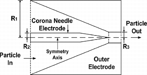
The schematic diagram of the needle corona charger with a fixed geometry is shown in The charger consists of an inner electrode ended in a sharp point, coaxial with an outer electrode which has a conical shape. The radii of the inlet (R 1) and outlet (R 3) conical sections are 10 and 1.75 mm, respectively. The radius of the corona needle electrode (R 2) is 1.5 mm, and the height of the cone is 20 mm. The flow field inside the charger was simulated by solving two-dimensional (2-D) continuity and Navier-Stokes equations in cylindrical coordinates, assuming steady, incompressible, and laminar fluid flow. Air was assumed to be at 20 °C and 1 atm. The governing equations were discretized using the finite volume method and solved by the SIMPLE algorithm (CitationPatankar, 1980). Grid independence checks for modeling the charger were performed using different grid spacings and the 40,000 grids were found to obtain a grid-independent solution (CitationHuang and Alonso, 2011). The continuity and Navier-Stokes equations describing the flow field within the charger are thus:
Figure 1. Schematic diagram of the needle charger.
where ρ is the air density, P is the pressure, is the air velocity vector, and μ is the air viscosity. For calculation of the electric field distribution inside the charger, the space charge between the corona discharge electrode and the outer grounded electrode was considered in addition to the externally applied potential difference between them. The electric field distribution in the charger was simulated by solving 2-D Poisson's equation in cylindrical coordinates as follow:
where is the electric potential,
is the space charge density, and ϵ0 is the vacuum permittivity. The space charge density was calculated by the convection-diffusion equation as:
where D is the ion diffusion coefficient, is the electrical mobility of the ions, and
is the electric field strength. The space charge density can be expressed as the ion concentration,
, multiplied by the elementary unit of charge, e. Ion concentrations of about 2.5 × 10¹⁴ to 6.2 × 10¹⁴ ions/m3 were calculated at the discharge surface of the needle charger for various voltages. The mean ionic velocity, equal to the product of the electrical mobility of ions and the electric field strength, was added to the main stream flow velocity to form an effective velocity,
. The electric field strength in Equationeq 4 can be calculated as:
After calculating the electric field and flow field inside the charger, the number of charges acquired by the particles, through the combined mechanisms of diffusion and field charging, was calculated along the particle trajectory using the expressions (CitationHinds, 1999; CitationWhite, 1963):
where ,
, and
are the number of charges on the particle for the total, diffusion, and field charging at the jth position,
(
) and
are the traveling time and average electric field strength between positions j and j − 1,
and
are the distance and average particle velocity between positions j and j − 1, T is the gas temperature, K is Boltzmann's constant,
, C
i is the mean thermal speed of ions, and ε is the dielectric constant of the particle.
To yield the particle trajectories, the particle motion equation was integrated using the fourth-order Runge-Kutta method. Particle motion is governed by the following equation:
where C
d is the empirical drag coefficient, Re
p is the particle Reynolds number, D
p is the particle diameter, C is the Cunningham correction factor, is the electrical force (
), e is the elementary unit of charge, n
T is the total number of charges on the particle, m
p is the particle mass,
is the Brownian random force (
,
) (CitationAbouali et al., 2009; CitationLi and Ahmadi, 1992), β is the inverse of the particle relaxation time, G is a zero-mean, unit variance independent Gaussian random number,
is the time step, and
is the particle velocity.
Results and Discussion
Particle trajectory
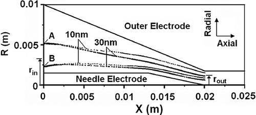
This investigation has calculated the particle trajectory using numerical methods to obtain the number of charges on charged nanoparticles within a needle charger for various conditions. displays the trajectories of particles with diameters of 10 and 30 nm launched at an inlet radial position, , of 0.52 (point A) and 0.23 (point B), for an applied voltage of 3.6 kV and a flow rate of 2 L/min. For particles introduced far away from the symmetry axis (point A), the trajectories of the 10 nm particles depart significantly from the corresponding streamlines and also from those of 30 nm particles because the electrical migration velocity of 10 nm particles is larger than that of 30 nm particles. The electric field is perpendicular from the surface of the corona needle toward the outer electrode, thus it forces nanoparticles to move to the outer wall. Similar results can be observed for the case of particles introduced close to the symmetry axis (point B). In the case of point B, the trajectories are closer to the needle electrode than those starting from point A. The illustrative trajectories shown in indicate that the output location of charged particles is related to the particle diameter, the radial input position entering into the charger, the field strength, and the air flow velocity. The influence of these variables can be quantitatively determined with the proposed model.
Figure 2. Particle trajectories in the charger for applied voltage of 3.6 kV and flow rate of 2 L/min.
Particle charging along axial distance
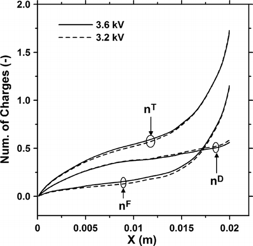
shows the number of charges on the charged particles as a function of the axial distance along the charger, X, for applied voltage of 3.2 and 3.6 kV at a flow rate of 8 L/min, the particle diameter of 30 nm and the inlet radial position () of 0.27. The plot shows that the number of charges acquired by diffusion charging,
, is higher than that by field charging,
, for the axial distance less than 0.017 m; beyond this point the number of charges acquired by field charging is higher because the electric field strength is larger in the outlet region of the needle charger, i.e., near the needle tip, and the field charging is more significant. In addition, the number of charges per particle by diffusion charging along the axial distance is similar for 3.2 and 3.6 kV. The number of charges per particle by field charging for 3.6 kV is slightly higher than that for 3.2 kV.
Figure 3. Number of charges per particle as a function of axial distance along the charger for different applied voltages. (,
, and
: number of charges by total, diffusion, and field charging.)
Influence of radial particle location on number of charges
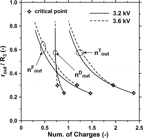
shows the influence of the radial particle location, , on the number of charges per charged particle at the exit section (X = 0.02 m) of the charger for 10 and 30 nm particles at a flow rate of 2 L/min and applied voltage of 3.6 kV. It is seen that for both particle sizes,
(the number of charges acquired by diffusion at the outlet) keeps almost constant for different values of
, whereas
(number of charges acquired by field charging at the outlet) and, thus, the total number of charges,
, increase with decreasing values of
. A decreasing value of
means that the outlet radial position of the particle becomes closer to the needle tip, where the electric field strength is higher, and hence a higher value of
can be reached.
Figure 4. Outlet radial location versus number of charges per particle for different particle diameters.
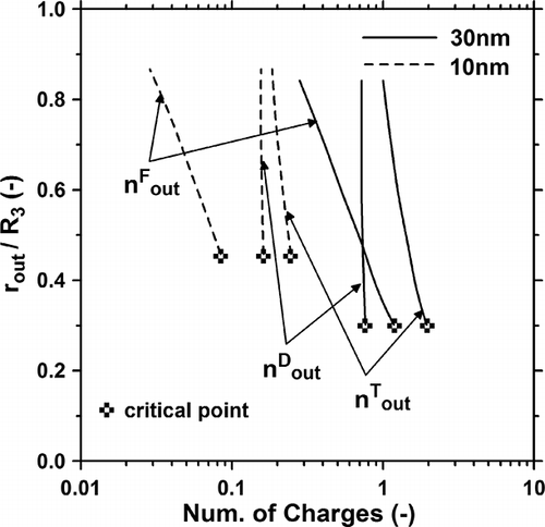
The critical point, shown in the figure, represents the minimum distance between the symmetry axis and the radial position reached by the particles at the outlet of the charger. That is, there are a maximum value of (
) and a minimum value of
(
) when the particle reaches the critical point. The results show that
is larger for 10 nm than for 30 nm particles, because the smaller particles move to the outer wall more rapidly than the larger ones. In addition,
for D
p = 30 nm is higher than that for D
p = 10 nm. shows the influence of the radial particle location on the number of charges per charged particle for different applied voltages at Q = 2 L/min, D
p = 30 nm, and X = 0.02 m. The results show that
is almost the same for both 3.2 and 3.6 kV, whereas
and
are larger for 3.6 kV before reaching the critical point. At a voltage of 3.2 kV the particles reach a critical point that is closer to the needle tip, thus yielding a larger value of
.
Figure 5. Outlet radial location versus number of charges per particle for different applied voltages.
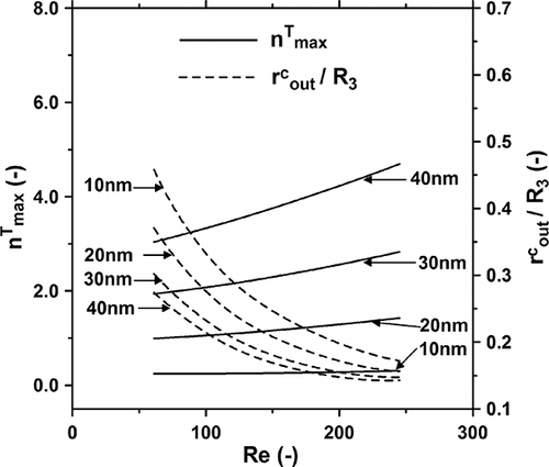
Effect of Reynolds number on  and
and
Figures 6 and 7 show the influence of Reynolds number ();
is the air velocity at the charger inlet;
is the air kinematic viscosity) on the maximum number of charges (
) and the critical outlet radial position (
) for applied voltages of 3.2 and 3.6 kV, respectively, by changing the flow rate through the charger. shows that
increases with increasing Reynolds number for particles larger than 20 nm, but is practically independent of Re for smaller particles. A higher Reynolds number implies a shorter residence time and, hence, a lower number of charges acquired by diffusion charging. However, the number of charges acquired by field charging is higher for the higher Reynolds number because the particles can become closer to the needle tip to yield the larger value of
. also shows that
decreases with the Reynolds number in all the particle size range examined. Similar results were obtained for the case of 3.6 kV, shown in It is seen that slightly lower values of
and slightly higher values of
are obtained at 3.6 kV in comparison with 3.2 kV.
Figure 6. Effect of Reynolds number on the maximum number of charges and critical radial outlet location for applied voltages of 3.2 kV.
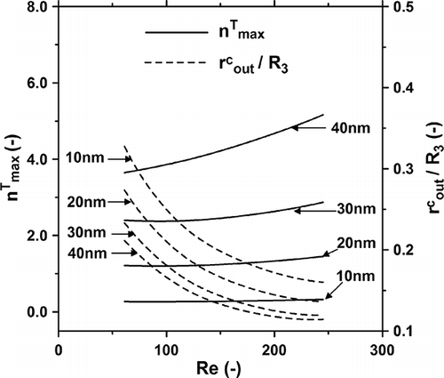
Figure 7. Effect of Reynolds number on the maximum number of charges and critical radial outlet location for applied voltages of 3.6 kV.
Conclusions
In this study, the number of charges per charged particle at the outlet of a needle charger was investigated by simulating the flow field, electric field, particle charging process by diffusion and field charging mechanisms, and particle trajectory. The proposed model allows quantitative determination of the influence of particle location on number of charges per charged particle in the 10–40 nm size range at the outlet of the charger under various conditions. This study shows that there are a maximum number of charges per particle and a minimum radial distance between the symmetry axis and the charged particles at the outlet of the charger. The maximum number of charges per particle increases with increasing Reynolds number for particles larger than 20 nm, whereas the minimum outlet radial location decreases with the Reynolds number for the examined particle sizes. Although the present study has been restricted to the modeling of a particular corona charger, its applicability of the influence of particle location on the number of charges on particles can be extended to other chargers with different designs and conditions. In the future, the developed numerical models will be used to investigate the average number of charges on nanoparticles at the outlet of the charger under various conditions.
Acknowledgments
The authors would like to thank the National Science Council of the Republic of China, Taiwan, under the contract number NSC 99-2923-E-264-001-MY2, and Spain's CSIC (grant 2009TW0017) and Ministerio de Ciencia e Innovación (grant DPI2008-06199) for partly supporting this research.
References
- Abouali , O. , Nikbakht , A. , Ahmadi , G. and Saadabadi , S. 2009 . Three-dimensional simulation of brownian motion of nano-particles in aerodynamic lenses . Aerosol Sci. Technol. , 43 : 205 – 215 .
- Alguacil , F.J. and Alonso , M. 2006 . Multiple charging of ultrafine particles in a corona charger . J. Aerosol Sci. , 37 : 875 – 884 .
- Alonso , M. and Alguacil , F.J. 2002 . Electrostatic precipitation of ultrafine particles enhanced by simultaneous diffusional deposition on wire screens . J. Air Waste Manage. Assoc. , 52 : 1342 – 1347 .
- Chen , D.R. and Pui , D.Y.H. 1999 . A high efficiency, high throughput unipolar aerosol charger for nanoparticles . J. Nanoparticle Res. , 1 : 115 – 126 .
- Han , S. , Chen , D.R. , Pui , D.Y.H. and Anderson , B.E. 2000 . A nanometer aerosol size analyzer (nASA) for rapid measurement of high-concentration size distributions . J. Nanoparticle Res. , 2 : 43 – 52 .
- Hernandez-Sierra , A. , Alguacil , F.J. and Alonso , M. 2003 . Unipolar charging of nanometer aerosol particles in a corona ionizer . J. Aerosol Sci. , 34 : 733 – 745 .
- Hinds , W.C. 1999 . Aerosol Technology , New York : John Wiley and Sons .
- Huang , C.H. and Alonso , M. 2011 . Nanoparticle electrostatic loss within corona needle charger during particle-charging process . J. Nanoparticle Res. , 13 : 175 – 184 .
- Kwon , S.B. , Sakurai , H. and Seto , T. 2007 . Unipolar charging of nanoparticles by the surface-discharge microplasma aerosol charger (SMAC) . J. Nanoparticle Res. , 9 : 621 – 630 .
- Li , A. and Ahmadi , G. 1992 . Dispersion and deposition of spherical particles from point sources in a turbulent channel flow . Aerosol Sci. Technol. , 16 : 209 – 226 .
- Li , L. , Chen , D.R. and Tsai , P.J. 2009 . Use of an electrical aerosol detector (EAD) for nanoparticle size distribution measurement. J . Nanoparticle Res. , 11 : 111 – 120 .
- Li , Y. , Suriyawong , A. , Daukoru , M. , Zhuang , Y. and Biswas , P. 2009 . Measurement and capture of fine and ultrafine particles from a pilot-scale pulverized coal combustor with an electrostatic precipitator . J. Air Waste Manage. Assoc. , 59 : 553 – 559 . doi: 10.3155.1047-3289.59.5.553
- Lin , G.Y. , Tsai , C.J. , Chen , S.C. , Chen , T.M. and Li , S.N. 2010 . An efficient single-stage wet electrostatic precipitator for fine and nanosized particle control . Aerosol Sci. Technol. , 44 : 38 – 45 .
- Park , D. , An , M. and Hwang , J. 2007 . Development and performance test of a unipolar diffusion charger for real-time measurements of submicron aerosol particles having a log-normal size distribution . J. Aerosol Sci. , 38 : 420 – 430 .
- Patankar , S.V. 1980 . Numerical Heat Transfer and Fluid Flow , Washington , DC : Hemisphere .
- Qi , C. , Chen , D.R. and Greenberg , P. 2008 . Performance study of a unipolar minicharger for a personal nanoparticle sizer . J. Aerosol Sci. , 39 : 450 – 459 .
- Saiyasitpanich , P. , Keener , T.C. , Lu , M. , Liang , F. and Khang , S.-J. 2008 . Control of diesel gaseous and particulate emissions with a tube-type wet electrostatic precipitator . J. Air Waste Manage. Assoc. , 58 : 1311 – 1317 . doi: 10.3155/1047-3289.58.10.1311
- Tsai , C.J. , Lin , G.Y. , Chen , H.L. , Huang , C.H. and Alonso , M. 2010 . Enhancement of extrinsic charging efficiency of a nanoparticle charger with multiple discharging wires . Aerosol Sci. Technol. , 44 : 807 – 816 .
- Wang , Y. , Zhu , Y. , Salinas , R. , Ramirez , D. , Karnae , S. and K , John . 2008 . Roadside measurements of ultrafine particles at a busy urban intersection . J. Air Waste Manage. Assoc. , 58 : 1449 – 1457 . doi: 10.3155/1047-3289.58.11.1449
- White , H.J. 1963 . Industrial Electrostatic Precipitation , Boston : Addison-Wesley .