ABSTRACT
In shallow water off the coast of West Sussex in England lies the wreck of a French built, English warship, lost in 1706. The remains represent a hybrid of French construction and armament with English organisation and adaption. This paper brings the site’s investigations up to date, discussing new records relating to the structure and internal layout of the main site, as well as the discovery of several new areas, rich in guns and other artefacts.
RESUMEN
En aguas superficiales frente a la costa de West Sussex en Inglaterra yacen los restos de un buque de guerra inglés de construcción francesa perdido en 1706. Los restos representan un híbrido de construcción y armamento franceses con organización y adaptación inglesas. En este artículo se actualizan las investigaciones del sitio y se discuten los nuevos registros relacionados a la estructura y el diseño interno del sitio principal, así como el descubrimiento de nuevas áreas, ricas en cañones y otros artefactos.
摘要
英格兰西萨塞克斯郡海岸附近的浅水区中有一艘法国建造的英国战舰残骸,该舰于1706年沉没。其代表了一种由法国建造和装备结合了英国组织和改装的混合体。本文介绍了对该遗址的最新调查情况,讨论了与主遗址的结构和内部布局有关的新记录,以及发现的几个包含有大量枪支和其他文物新区域。
摘要
英格蘭西薩塞克斯郡海岸附近的淺水海域有一艘法國建造的英國戰艦殘骸,該艦於1706年沉沒。其代表了一種由法國建造和裝備結合了英國組織和改裝的混合體。本文介紹了對該遺址的最新調查情況,討論了與主遺址的結構和內部布局有關的新記錄,以及發現的幾個包含有大量槍支和其他文物新區域。
المُستخلص
يقع حُطام السفينة الحربية الإنجليزية والفرنسية الصنع والتي فُقدت عام ١٧٠٦في المياه الضحلة قبالة سواحل غرب ساسكس في إنجلترا. تُمثل البقايا مزيجاً من البناء الفرنسي والتسليح مع التنظيم والتكيف الإنجليزي. تُقدم هذه المقالة أعمال التحقيق التي أجريت في الموقع حتي الآن، وتناقش السجلات الجديدة المتعلقة بالهيكل والتخطيط الداخلي للموقع الرئيسي، هذا إلي جانب اكتشاف عدة مناطق جديدة غنية بالبنادق وغيرها من القطع الأثرية.
الكلمات الدلالیة:
Introduction
Originally Hasardeux, the ship was designed and built by Pierre Coulombe at Port Louis, near Lorient in 1699 and commissioned as a third-rate of 50 guns in 1701 (Winfield, Citation2009, p. 144; Winfield & Roberts, Citation2017, p. 133). Hasardeux served for a short period in the French Navy between 1701 and 1703. During that time the ship’s most notable operation was in the Caribbean as part of an escort fleet under the command of François Louis Rousselet Châteaurenault. In July 1702 Châteaurenault was given the orders to escort a combined merchant and Spanish treasure fleet back to Cadiz (Calmon-Maison, Citation1903). During the voyage news reached Châteaurenault that an English fleet was lurking in the waters off Cadiz, so he diverted to Vigo (Browning, Citation1897, p. 214). On arrival at the Port of Vigo in late September, members of the fleet not bound for Cadiz moved on: Hasardeux headed north for Brest and merchant vessels headed for their respective ports (Calmon-Maison, Citation1903). This was extremely fortuitous as on 12 October 1702 the ships that remained were attacked by an Anglo-Dutch fleet, commanded by Admiral George Rooke, who inflicted heavy losses on Châteaurenault’s fleet at what became known as the Battle of Vigo Bay (Browning, Citation1897, p. 232).
Six months later the French Navy loaned Hasardeux to the Privateer Beaubriant-L’Éléque from St Malo (Winfield & Roberts, Citation2017, p. 133). By 14 November 1703, while in transit from Newfoundland, she was captured in the western approaches to the English Channel by three English warships of the Channel squadron (TNA, HCA Citation32/Citation62/Citation35). To place this date in context, this was only 12 days before the most ferocious storm hit Britain’s shores, since remembered as the ‘Great Storm’, causing widespread destruction and the loss of several ships and hundreds of sailors of the Royal Navy (Defoe, Citation1704). Three of those ships, Stirling Castle, Northumberland and Restoration have been found and subsequently protected, and offer comparable contemporary evidence for the material from the wreck of Hazardous (Pascoe & Peacock, Citation2015; Whitewright, Citation2020).
Within six months of Hasardeux’s capture she was re-commissioned into the Royal Navy as Hazardous Prize, a 54-gun fourth-rate, armed with batteries of 22 18-pounders, 22 12-pounders and ten 6-pounders (TNA, ADM Citation106/Citation586/Citation285), 49 of which were the original French guns (TNA, ADM Citation106/Citation594/Citation45).
Hazardous was mainly assigned for convoy duties and her last order was to escort a merchant fleet back from Virginia, under the Command of Captain Barrow Harris (TNA, ADM Citation106/Citation609/Citation106). Before the ship departed for Virginia, Captain Harris left the ship and the Command was given to Captain Richard Browne. By 19 November 1706, following her return from Virginia, Hazardous was wrecked close to shore off the West Sussex coast, at Bracklesham Bay. (For further historical context of the ship and site investigations up to 1991, see previous publications in The International Journal of Nautical Archaeology and Exploration and the International Journal of Nautical Archaeology by the late Norman Owen [Owen, Citation1988, Citation1991]).
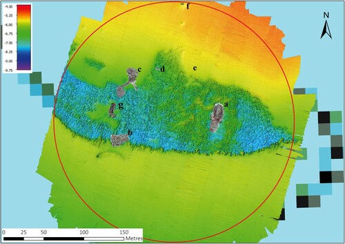
Since Owen’s last report the site has changed considerably with new features of the wreck becoming exposed and, unfortunately, parts of it being totally lost to erosion. Incredibly, six completely new and substantial areas of wreck material have been found since 2014, which have included up to a further 25 guns, bringing the grand total of guns confirmed on the seabed to 38. These new areas will be referred to as the 2014, 2019, 2022 gun sites, gun 35, gun 36, and the spar site (); all lie within a protected area. With the exception of the spar site, these areas have all been recorded photogrammetrically and georeferenced onto recent multibeam surveys as shown in .
Prior to 2014 only 13 guns were known to exist on the main site and which were labelled alphabetically A-M (guns D and I were recovered in 1986 (Owen, Citation1991, p. 329)) with a lone gun 90 m to the northwest (now labelled gun 35). As the current count is 38 guns, they are now labelled 1–38. Historical records state that 21 guns were recovered by June 1707 (TNA, ADM Citation106/Citation625/Citation144) taking the total number of guns either salvaged or identified on the seabed to 59, five more than which she was originally commissioned. The greater number of guns has led to the reliability of the contemporary salvage reports being queried and the possibility that these guns are evidence of another site in the vicinity. The survey report following her capture, however, reveals Hazardous’ maximum capability was in fact 60 guns, being pierced for 24 guns on each of the main and upper gundecks, ten on the quarter deck and two on the forecastle (TNA, ADM Citation106/Citation594/Citation45). Examination of the penultimate Captain’s log revealed Hazardous still had 54 guns by 19 February 1706 (TNA, ADM Citation51/Citation4217), so if additional guns were added it would have been at some point prior to her leaving for her last operation to Virginia. As yet no records have been found to confirm this.
This report will discuss the site’s investigations from 1992 to the present. This work has been conducted by the Hazardous Project Group (HPG previously 308 Sub Aqua Association), led by Licensee Iain Grant with assistance from several archaeological advisers and organisations, such as the Maritime Archaeology Trust (then Hampshire and Wight Trust for Maritime Archaeology) who looked at environmental monitoring and bed-level change (Hampshire and Wight Trust For Maritime Archaeology, Citation2006), contributing to justification for excavation, and Alex Hildred (Mary Rose Trust) who contributed her expertise in underwater recording, ordnance, as well as general archaeological advice. As a result of these contributions and the team’s efforts, a wealth of information has been recorded and recovered from the site in the last 30 years and this paper will attempt to consolidate a significant part of that work. It will begin with the latest interpretations of the main site, focusing on the hull structure and evidence of the internal layout of the ship. This has been done by combining the information recorded on the old hand drawn site plan with recent photogrammetric surveys. The latter includes a survey of the whole site, as well as more focused surveys of key areas, which were either exposed through natural erosion or targeted excavation (). This will be followed by an assessment of the new areas discovered since 2014. In light of the more recent discoveries, new interpretations of site formation processes post-wrecking have been developed and will be discussed at the end of this report.
Due to the discovery of so many more guns alongside the abundance of gunnery related material, a second paper will focus on the ship’s ordnance and the evidence relating to how the gunnery system was operated, organised and maintained on board. A third paper will discuss other significant artefacts relating to the other aspects of shipboard life and culture.
Site Location and Environment
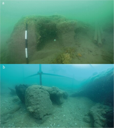
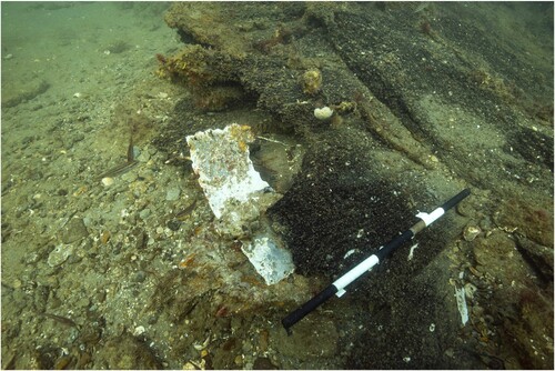
The wreck site currently consists of several separate areas of wreck material spread out within a designated area with a radius of 150 m, which is protected by law under the Protection of Wrecks Act 1973. These areas lie in 5–8 m of water, less than 1 km from the beach, southeast of Bracklesham slipway (). Mobile banks of sand are currently situated directly to the north and south and their migration back and forth can periodically bury the site (). When exposed, the site lies in a boulder field that has formed from the erosion of clay and fossil bed formations.
Figure 1. Site location in Bracklesham Bay, West Sussex, on the south coast of England (Authors).
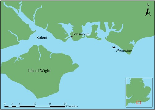
Figure 2. The designated area (150 m radius) with photogrammetric surveys georeferenced onto the 2020 multi-beam bathymetry. A) main site, B) 2014 gun site, C) 2019 gun site, D) gun 35, E) spar site, F) gun 36 and G) 2022 gun site (MBES survey conducted by MSDS Marine and Swathe Services on behalf of Historic England and HPG).
The Main Site
Since 1992 the character of the site has changed considerably. Over the course of a single winter in 1995 the entire aft section of port side structure was lost (), the only evidence of shipwreck remains left in this area being guns 3–5, to the west of this position. A significant proportion of the wreck had disappeared during a single winter, demonstrating, the vulnerability of wooden shipwreck sites when exposed in shallow dynamic environments. After being engulfed by a large sand wave in 2009, the main section of the site remerged again in 2014, remaining uncovered ever since; another demonstration of the mobility and dynamics of the seabed in the locality.
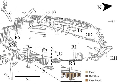
Figure 3. Main site plan adapted from Owen, Citation1991 plan showing the southern area which was lost in the winter of 1995. Guns are labelled 3–13, GD – Gundeck, R1–5 – Riders 1–5, KH – Knee of the head and SM – shot mound (© HPG).
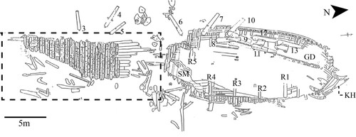
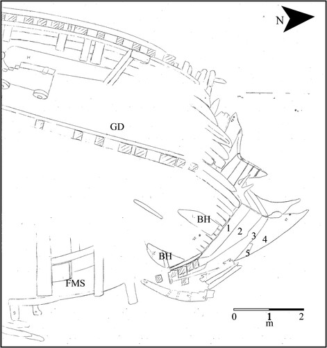
The surviving northern section of the site consists of one coherent 20 m-long section of the port side, inside up, from roughly amidships to the head of the bow and from the main gundeck down to the keel, which lies on the eastern edge and which was not exposed in the 1991 survey ( and ). It has not escaped degradation, as sustained periods of exposure have led to the deterioration of all exposed timber structure through biological, chemical and physical processes. Since Owen’s 1992 description of this section of the site it has lost 4 m in length. This is most noticeable at the head of the bow which has radically reduced in size ( and ). In 2017, as surface sediments continued to wash away, the keel emerged for the first time (); the continual loss of surface sediments since 2014 has been a clear indication of the impact of wave action in the shallow depth of water.
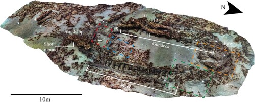
Figure 4. 2019 3D textured model of the main site. Guns are labelled 3–13. The area marked in red denotes the 2018 excavation trench, represented in and ; the area marked in blue denotes the location of exposed barrels, represented in ; the area in green denotes the foremast-step and forefoot, represented in and the area in orange denotes the area of the forward platform, represented in . All areas were naturally exposed except for the 2018 excavation trench (survey and model produced by Daniel Pascoe).
The bowl-like characteristic of the surviving structure has helped trap sediments within the wreck. However, as the southern end of the structure is eroding down this is allowing sediments to wash out at this end of the site, exposing internal structures and artefacts related to the ship’s stores. Exposed artefacts that are liftable by hand were recorded in-situ and then recovered, but large artefacts, such as gun carriages, have been left because of a lack of funding to either recover or conserve them. Unfortunately, as a result of exposure, very little remains of these carriages but their details were recorded on the seabed by the HPG, with assistance from archaeologist and ordnance specialist, Dr Alex Hildred. The carriages will be analysed in detail in the second paper.
Gundeck
A series of exposed ends of deck beams, lodging and hanging knees protrude from the sand, defining the location of the gundeck remains. The surviving section of gundeck is 14 m long and its maximum depth is approximately 1 m at the location of guns 12 and 13 (). There are seven guns lying on the surviving deck and hull structure ( and ): guns 7 and 10 are orientated with their chase pointing through the side of the surviving hull structure, which was the probable location of gun ports. Guns 12 and 13 are orientated at right angles to their adjacent gunports with muzzles facing forward. This was probably deliberate because of the reduced space at the forward end of the deck, as it narrows towards the bow. Guns 8, 9 and 11 are lying across guns 10 and 12 and most likely originated from the starboard side, sliding across during the wrecking process. Guns 12 and 13 still have parts of their carriages surviving, although, as noted above, these have deteriorated considerably since exposure.
Figure 5. Image from the 2019 textured model, showing position of deck beams. Scales are 1 m with 20 cm increments (survey and model produced by Daniel Pascoe).
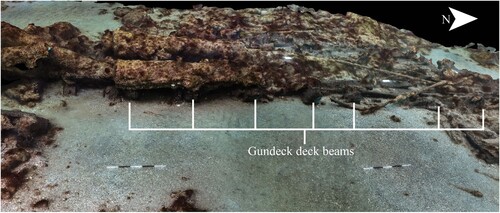
Deck Beams
From the bow end heading aft are the remains of seven consecutive deck beams. The beams are all 305 mm (12 in) sided and their moulded dimensions are 280 mm (11 in). The spaces between the beams are irregular, ranging from 0.71 m between beams 3 and 4 and up to 1.66 m between beams 2 and 3. This is not unusual as the beams would have had to fit around the masts and hatch ways along the centre line of the deck () (Sutherland, Citation1717, p. 77).
Knees
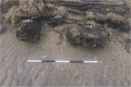
Below the level of the deck, and either side of the deck beams, are the eroded ends of wooden knees. The purpose of the knees was to brace the deck with the side of the hull and a combination of hanging and lodging knees were used: the lodging knees brace the deck fore and aft and the hanging knees brace the deck vertically. Due to the current level of sand, it is not possible to distinguish between hanging and lodging knees at all locations of the deck beams. The exceptions are at beam 1 and beam 3. At beam 1 there is only a hanging knee located on the aft side, which extends diagonally down and aft rather than vertically from the side of the beam (). It is substantial in build with a 320 mm (12.6 in) sided dimension. The lack of a lodging knee is likely due to the lack of space at the forward end of the deck. Due to the lack of space between beam 3 and 4 there appears to be only space for a hanging knee on the aft side of beam (). Evidence from the later wreck, and larger ship, of Invincible (1744–58) recorded lodging knees on the aft side and iron hanging knees on the forward side of the four most forward deck beams (Bingeman, Citation2010, p. 52 and personal observations during the 2017–19 excavations). The evidence from Hazardous suggests that where there was insufficient space between beams for lodging knees, hanging knees were used instead.
Figure 6. Hanging knee on aft side of gundeck beam 1 (GDB 1). Scale is 1 m with 20 cm increments (photo by Daniel Pascoe).
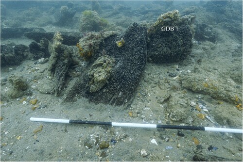
Figure 7. Hanging knee fastened on the aft side of gundeck beam 3 (GDB 3). Scale is 1 m with 20 cm increments (photo by Daniel Pascoe).
Ledges
Also visible between beams 1–2 and 2–3 are very closely spaced ledges, which support the deck in between the deck beams. They are 220 mm (8.7 in) sided by 80 mm (3.1 in) moulded. As with the end of the deck beams the ends of the ledges will rest inside recesses along the gundeck deck clamp and upper surfaces of the lodging knees.
The remainder of the structural features of the deck are buried and would require significant excavation to record dimensions. Aft of beam 7 the remains of the main deck structure are more eroded and less discernible. Beam 8 appears to be missing, along with its lodging knee, possibly ripped out during the wrecking or salvage events, but associated hanging knees have remained. Gundeck planking does survive but only one plank is partially exposed which has an approximate thickness of 80 mm (3.1 in).
On the inside of the hull above the level of the deck there are a series of knees between the gunports that are likely to be the vertical arms of hanging knees, which supported the upper gundeck, and possibly the vertical arms of rising knees supporting the main gundeck. Guns 7, 10, 12 and 13 mark the position of gunports and the 1991 site plan identifies the location of three knees between the ports of guns 10, 12 and 13 (). The exposed structures of the hull are too degraded to take reliable dimensions of gunport sizes.
Orlop/Platform Deck
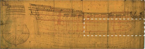
The orlop is less visible partly due to burial but also because the orlop on Hazardous was probably only a partial deck – the latter was certainly true for English built fourth-rates up until approximately 1800 (Winfield, Citation2005), where, instead of a continuous deck the orlop was divided into three platforms. A useful comparison is the contemporary ship, Superb: although no draughts of Hazardous have been found, there is a draught of this 64-gun French warship. Superb was built in 1708, also by Pierre Coulombe at Port Louis and captured in 1710 by the British, being subsequently recommissioned as a fourth-rate of 56–64 guns. Superb had a length along the gundeck of 143 ft 6 in long, a breath of 40 ft 2 in and burthen weight of 1020 tons, which was 6 ft 6 in longer, 2 ft wider and 145 tons heavier than Hazardous (Winfield & Roberts, Citation2017, p. 138). Despite these differences, the draft of Superb makes for a useful comparison when trying to determine the location of the orlop platforms and other structural features and internal layout. This is particularly the case because the Admiralty produced a draft of Superb following her capture showing that the orlop was divided into three separate platforms, as described above (). The internal layout of store-rooms and compartments on French and British warships differed. For example on French warships the gunner’s store, known as the lady’s hole, was located at the extreme aft end of the orlop or platform deck and this gave the gunner close access to the main powder room below and to the gunroom above (Boudriot, Citation1986b, p. 59). Conversely, on a British warship the gunner’s store was found at the forward end with access to the main magazine. Assuming, then, that the internal arrangements were altered when Hazardous was refitted as an English man-of-war – as was standard practice – the forward platform was where the carpenter’s, boatswain’s and gunner’s storerooms were located, the latter allowing close access for the master gunner to the main magazine below (Endsor, Citation2020, p. 234; Winfield, Citation2005, p. 71). The artefacts so far recovered would suggest this was the case. The amidships platform was where the anchor cables were stowed and the aft platform accommodated the warrant officers, the surgeon and stores for the purser, captain and lieutenants (Endsor, Citation2020, p. 234; Winfield, Citation2005, p. 71).
Figure 8. Plan of Superb showing layout of the internal arrangements of the platform deck. The dotted line represents the surviving section of Hazardous (Image ZAZ1811 © National Maritime Museum, Greenwich, London and is reproduced under their fair usage / commitment to support education and scholarship and encourage research, https://images.rmg.co.uk/price-list/). Creative Commons Attribution, Non-Commercial No Derivatives (CC BY-NC-ND) licence terms apply.
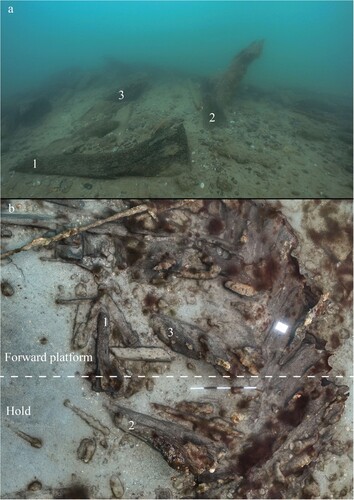
Relevant to the current structural remains of Hazardous are the amidships and forward platforms and the space between the two, which allowed direct access to the hold. Excavation of a small and currently unfinished trench at the southern end of the structure uncovered structural evidence of part of what is possibly the amidships section, forward of the main mast. This consists of inner hull planking, frames and a wooden knee ( and ). The next visible structural evidence of the platform structures are the eroded remains of a rising knee towards the forward end of the platform and aft of two exposed breast hooks (). The knee is just aft of the remains of two breast hooks and likely represents the forward-most end of the forward platform.
Figure 9. Orthophoto mosaic of 2018 excavation trench. OP – outer planks, F – frames, IP – inner planks, PDC – platform deck clamp, CP – ceiling planks, R5 – rider 5, FW – firewood, dashed line – scarphs. Scales are 1 m with 20 cm increments (survey and model produced by Daniel Pascoe).
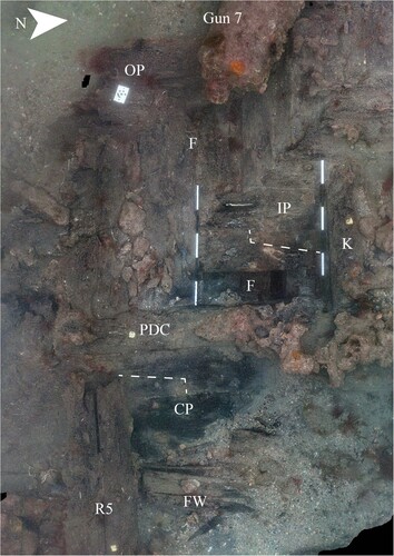
Figure 10. The dashed red line showing the space between the frames and the green dashed line showing that space filled by an additional timber, possibly known as a ‘filling’. Scales are 1 m with 20 cm increments (survey and model produced by Daniel Pascoe).
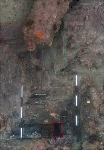
Figure 11. Structure from Invincible 1758. Photo A) showing filling timber between frame bends from starboard side stern structure from roughly gun deck level, the scale is 50 cm with 10 cm increments. Photo B) shows filling timber at roughly the floor heads on the starboard side amidships, the scale is 1 m with 20 cm increments (photos by Daniel Pascoe).
Inner Planking
The small excavation at the southern end of the orlop revealed the inner hull from immediately below the gundeck to just below the platform deck level. A thicker plank found at the centre of the trench identified the level of the platform deck (). The plank is 343 mm (13.5 in) wide and 130 mm (5.1 in) thick, which is noticeably thicker than the planks above and below. It is likely to be the platform deck clamp that served to support the ends of the platform beams and ledges. There is, however, no visible evidence of the rebates, as concretion obscures the northern section and the southern section has surface degradation. It also cannot be ruled out that this area was not decked and is possibly the space between the forward and amidships platforms. Above the deck clamp is a gap in the planking. This gap was intentional, known as an air strake, purposely left clear to allow air to circulate to the frames (Boudriot, Citation1986a, p. 101). It is noticeably smaller in breadth (270 mm/10.6 in) than the planks immediately above and below. An air strake was recorded just above the deck level of the orlop on Invincible, which was also notably smaller than surrounding planks, too (personal observations from the 2017–19 excavations).
Immediately below the deck clamp plank is a wider plank 408 mm (16 in) wide consisting of two ends scarphed together. Planks that were scarphed tended to be load bearing and this plank, along with the clamp, shared most of the platform deck’s load. This would appear consistent with the period, as Sutherland describes the inclusion of two strakes of orlop clamp either side of the hull in the building of warships, albeit English warships (Sutherland, Citation1717, p. 77). The next plank below is considerably smaller at 307 mm (12 in) wide and consists of two ends butt jointed; evidence of planks with less load to bear ().
Above the air strake are a row of four to five ends of eroded planks. The first two are in slightly better condition and the edges are more discernible. The first plank is 408 mm (16 in) wide and 100 mm (4 in) thick and consists of two ends scarphed together (). This is consistent with the planking below the gundeck that had to bear the weight of the heaviest guns. All planks are fastened to the frames by a mix of iron fixings and treenails, which appear in pairs at the top and bottom of the planks or as a single fixing at the end of a scarph.
Frames
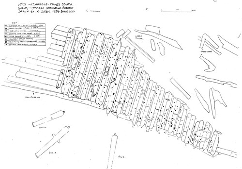
At the platform deck, the air strake and eroded planks have exposed the frames below. This is one of several areas on the wreck where the framing configuration of Hazardous is visible, showing that the hull was constructed with a system of double frames i.e. paired timbers, side by side and referred to as bends (Boudriot, Citation1986a, p. 80). At the location of the air strake, it is possible to see a space between two bends, but 960 mm above that space has been filled with a timber (). It is possible that this timber is what Boudriot refers to in the later construction of French 74s, as a ‘filling’. Fillings were wedged shaped timbers used to maintain the space between the frames and stiffen the floors, thus adding strength (Boudriot, Citation1986a, p. 99). Similar timbers have been found between frames on the structural remains of Invincible (). With the case of Invincible these filling timbers are located regularly and have been recorded in consecutive spaces between bends. This is not the case with Hazardous, as is clear from plan of the structure at the southern end of the site, which was lost in 1995 (). Here, no fillings were present between 19 consecutive frame bends, and they also do not appear with the exposed ends-of-frames along the eastern edge of the surviving section of the main site, suggesting that fillings were not a feature of the lower hull structure. Only further excavation will determine whether the filling is an isolated example or a feature more common at gundeck level and above. If they are regular features, it may have been a measure to make the structure from main gundeck level and above more resistant to gunshot.
The plan of the lost southern section of hull does show that the heel and heads of timbers were butt jointed and that the two timbers forming the bend were fastened together, fore and aft, by iron bolts (). The combination of double frames laterally fastened adds considerable strength and stiffness to the structure, improving the distribution of force across the hull (Batchvarov, Citation2002, pp. 154–155). A stiffer hull is also more resistant to the forces caused by the recoil of the guns and, as such, makes a stronger gun platform (Batchvarov, Citation2002, p. 155)
Figure 12. 1989 plan of the southern section of structure which was lost in 1995. It shows the double frame pattern with butt joints and fore and aft fixings but no filling timbers between frame bends (drawing N. Owen, ©HPG).
Knee
At the northern end of the trench is the eroded remains of a wooden knee extending up from the platform clamp, which suggests it is a rising knee. What remains of the vertical arm is 1.26 m (4 ft 1 in) long with a maximum moulded dimension of 290 mm (11.4 in). If this is a rising knee it may represent what is left of the forward end of the amidships platform, or possibly the aft end of the forward platform.
A second knee relating to the platform deck was located at the forward end, just aft of two breast hooks ( and ). The knee was in a fairly poor condition in 2019 and by 2021 it was gone. From the 2019 recording it appeared to be a rising knee with a vertical arm 1.28 m (4 ft 2 in) long, 250 mm (9.8 in) moulded and 200 mm (7.9 in) sided. As the original surfaces were heavily eroded these dimensions will not relate to the knee’s original size.
Figure 13 Image A) is a photograph looking north towards the head. Image B) is a plan view from the 2019 3D textured model. 1 – rising knee, 2 and 3 – breast hooks. The scale is 1 m with 20 cm increments (survey, photo and model produced by Daniel Pascoe).
Breast Hooks
Breast hooks serve to reinforce the bow and were shaped in the form of a V and fastened horizontally to the inside of the hull (Boudriot, Citation1986a, p. 102). The partial remains of two are currently visible: one at the end of the forward platform, of which only the port side arm survives, and a second, 1.1 m directly below it, which protrudes 1 m proud. The lower breast hook, which is located just beneath the level of the platform deck, still has part of the starboard arm surviving. The portside arm is 2 m (6 ft 6 in) long with a breadth of 345 mm (13.6 in). The breadth of the breast hook across its centre line (known as the throat in contemporary writings) is 1.2 m (3.9 ft) ().
Hold
Foremast-step
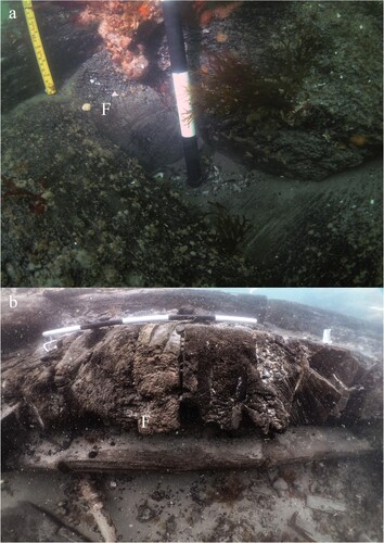
Continuing down the centre line the next exposed feature is the foremast-step. What survives is the port side half of the step and currently visible is a cross-sectional view through the centre line (). The visible remains show the foremast-step is located over the stemson and consists of a square step, boxed by several transverse and longitudinal timbers. A transverse timber known as a hook makes up the forward end of the step. At the aft end of the step is the forward rider. Running 90° between the hook and the rider is a mast-step carling, which slots into rebates on the upper surface of the hook and rider. Prior to the 2022 survey there was a block that was wedged at the aft end of the step, up against the forward face of the rider ( and ); this must have washed away at some point during the winter following the 2021 season. The block may have represented what Boudriot described as removable wedges, which allowed the position of the heel of the mast to be adjusted (Boudriot, Citation1986a, p. 105). The heel of the mast would have rested directly on the stemson and been secured within the step by wedges, as described above. The layout and construction of the foremast-step of the 74-gun Invincible is very similar () to Hazardous’ and to Boudriot’s interpretation, demonstrating a standard and successful practice over at least 45 years.
Figure 14. Image A) is a 2022 3D textured model of the remains of the port side of the foremast-step. H – hook, R – rider, MSC – mast-step carling, MS – mast-step, S – stemson, F – forefoot and RS – rising-wood. Image b) is a reconstruction taken from Boudriot’s drawing of a foremast-step. 1 – keelson, 2 – stemson, 3 – rider, 4 – mast-step carling, 5 – mast-step and 6 – hook (after Boudriot, Citation1986a, p. 103). The scales are 1 m with 20 cm increments (survey and model produced by Daniel Pascoe).
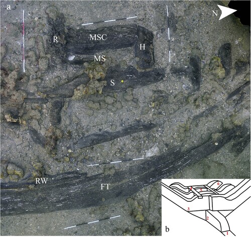
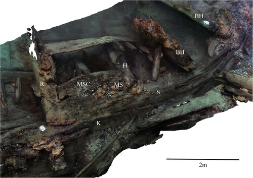
Figure 15. 3D textured model of the port side remains of Invincible’s foremast-step. R – rider, MS – mast-step, MSC – mast-step carling, H – hook, S – stemson, K – keelson and BH – breast hook. The scale is 50 cm with 10 cm increments (survey and model produced by Daniel Pascoe).
Riders
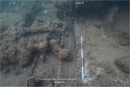
The riders are located in five positions along this forward section of the hull and are exposed to a greater extent at the southern end, where it is clear to see that they consist of two parallel timbers side-by-side ( and ). Each timber making up the pair is equal in size with a sided dimension of 320 mm (12.6 in). The space between the riders ranges from 2.40 to 2.77 m. The forward timber is known as the floor rider and the aft timber as the futtock rider. This is the opposite fashion to the laying of the frames in the forward half of the hull, where the floors are the aft timber. The role of the rider was to add rigidity to the hull and counteract the tendency of the frame to sag outwards (Boudriot, Citation1986a, p. 102). At the location of the three forward-most riders, only one timber of the pair is currently exposed. The current exposure of the hull reveals that rider 4 extends up the inside of the hull to just beneath the level of the main gundeck ().
Figure 16. Photo showing rider 4 extending up to below the gundeck level. Gun 8 represents gundeck level, F – Frames and IP – inner planking. The scale is 1 m with 20 cm increments (photo by Daniel Pascoe).
Frames
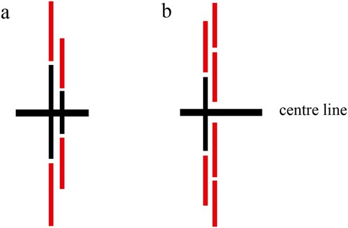
The framing configuration of the lower hull is visible along the eastern edge of the site, representing roughly the centre line of the hull. The keelson, limber boards and some ceiling planks are missing, which has revealed the frames beneath. Along this eastern edge the double framing pattern (bends) are clearly visible. In the case of Hazardous it would appear from the remains of the frames in the vicinity of rider 3 that each bend, as it crossed the keel, consisted of a floor and half floor. In the forward part of the hull the floor is the aft timber and the half floor the forward (Boudriot, Citation1986a, p. 88). The port side remains of the floors are visible along with the head of the half floors and in some locations the heal of the first futtock can be seen butting up to the head of the half floor (). This patterning appears similar to that found on the La Hougue wrecks D and E, identified as the 96-gun Le Merveilleux and the 94-gun Le Foudroyant, which were both built on the Atlantic coast at Brest in 1691 (L’Hour & Veyrat, Citation1999, p. 4; Citation2000, p. 13).
Figure 17. Plan of port side structure with exploded view of framing pattern (plan ©HPG, modified from Owen, Citation1991).
This system of double floors and futtocks would become common in French construction in the 18th century, demonstrated by the remains of Invincible, built in 1744. Evidence from the wreck of La Dauphine, built in 1703 and wrecked in 1704 in the entrance of St Malo, shows that the turn of the 18th century was still a transitional period in French construction as the earlier system of single floors and double futtocks was used. This is also recorded on the wreck of La Belle, lost in 1686 (Bruseth et al., Citation2017, p. 99). A similar but more robust system was used by the English in the construction of the 30 ships of the 1677 shipbuilding programme and which is evident from the wreck of Anne, lost in 1690. The remains of Anne reveal that frame bends (master frames) were located at every third frame station and timbers making up the bend were fastened laterally by wooden treenails. Filling frames were placed between the frame bends but were not fastened together laterally (Endsor, Citation2009, p. 43; Citation2017, p. 128). Given that Hazardous was built in 1698, double framing, therefore appears not to be unusual or typical of French construction but one of a few different variations. The most notable differences when comparing the double framing of Hazardous with the remains of English ships, such as Anne, is that with Hazardous there is greater space between the bends and a double floor and futtock system was used instead of a single floor and double futtock ().
Figure 18. Diagram A) represents the double floor and futtock system found on the Hazardous, la Hogue wrecks D and F and Invincible. Diagram B) shows the single floor and double futtock system found on La Belle and the English wrecks Anne and Northumberland. Floor timbers are black and futtocks are red (Authors).
Internal Layout
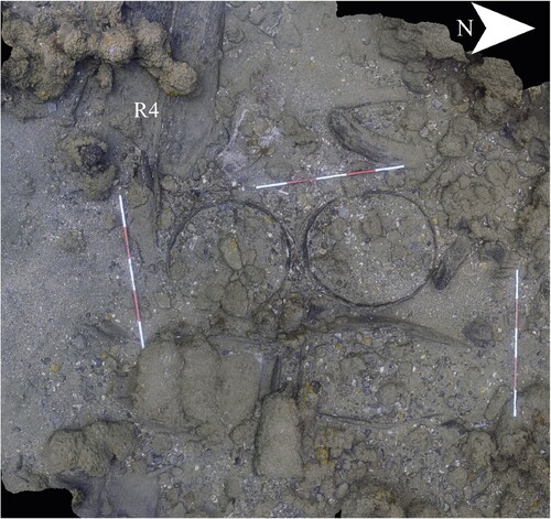
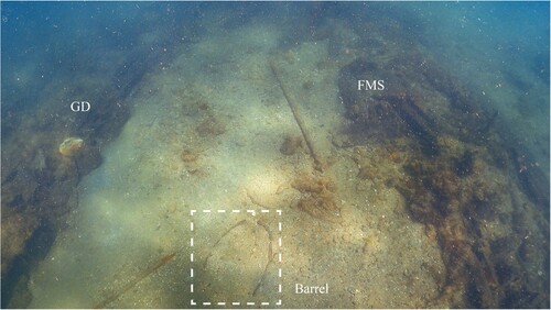
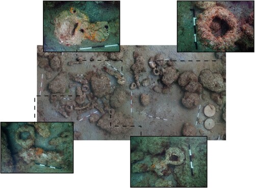
Despite not fully excavating the inside of the ship it is still possible to identify the likely internal layout, including storage areas, from the position of exposed artefacts. Starting at the southern end of the site there is a large shot mound that consists of round cast shot and wrought iron double headed shot. This represents the principal storage area for surplus shot and its current location suggests it was originally located in the hold forward of the main mast (). Between riders 3–4 and 4–5 is the location of the forward hold. This is the location of several large storage barrels, positioned upright and horizontal (). The large quantities of animal bone in this area suggests at least some of these barrels contained butchered meat.
Figure 19. 2022 3D textured model of group of barrels, one of which has been excavated and backfilled with sandbags, between riders 3 and 4. R4 – rider 4. The scales are 1 m with 20 cm increments (survey and model produced by Daniel Pascoe).
On the forward side of rider 5 there is a significant quantity of cut logs, which likely represent firewood for the ship’s galley (). Scattered amongst the barrels and firewood a variety of artefacts including rigging, gunnery and carpentry equipment have been found. Rigging equipment has included blocks, sheaves and parrel beads and gunnery equipment has included a rammer and sponge head, single gun tackle block and gun carriage truck. The lack of fixings, fixing holes or an any associated rope or tackle, strongly suggests all of these pieces were spares that most likely originated from the stores on the forward platform above, which belonged to the carpenter, boatswain and gunner (Winfield, Citation2005, p. 71).
The excavation in the area of the forward platform found a carpenter’s jack plane and a spare mast-cap two metres further forward, which became exposed naturally (). A mast-cap is a rectangular timber with two adjacent holes, one square and one circular, used to secure the upper masts to the lower masts. The tops of the lower masts were cut into a square tenon that slotted into the square hole on the cap, with the end of the upper mast being passed through the circular hole on the cap (Steel, Citation1796, p. 91). These are the type of artefacts that would be expected to be found in the storerooms on the forward platform.
Figure 20. Photo A) the mast cap as found in 2016. Image B) mast cap leaning against possible platform beam. Mast caps joined the tops of the lower masts to the upper mast. The square hole slotted onto a square tenon at the top of the lower mast and the upper mast passed through the circular hole. The scale is 50 cm with 10 cm increments (photos by Daniel Pascoe).
Between riders 1 and 2 is another partially exposed barrel lying in a horizontal position. This area is where the main magazine containing powder barrels would have been located (Winfield, Citation2005, p. 73), so it is highly likely that this barrel is a gunpowder barrel and that there could be others just beneath the surface ().
Figure 21. Photo showing outline of barrel just aft of the foremast-step. This would have been the location of the main magazine and filling room. GD – gundeck, FMS – foremast- step (photo by Daniel Pascoe).
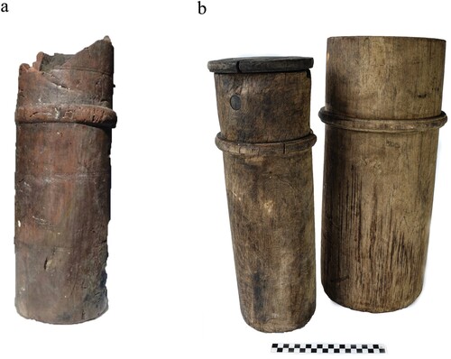
In 1988 an exploratory trench was excavated from the foremast-step across to the gundeck, which uncovered a fragment of a cartridge case. Cartridge cases were turned from a single piece of wood and had a separate lid attached by a lanyard (). They were used to transport a single charge of gunpowder from the filling room up to the gundecks. The filling room was located at the forward end of the magazine just aft of the fore mast (Winfield, Citation2005, p. 73), so this is another good indicator confirming that this is location of the magazine and filling room. In contemporary ordnance lists cartridge cases are listed as ‘cases of wood’ (TNA WO55/Citation1650). Evidence from the Duart Point wreck lost ca. 1650 (Martin, Citation2017), Hazardous and Invincible, lost 1758 (Bingeman, Citation2010), show that their form remained the same over that period ().
Figure 22. Image A) showing cartridge case from Hazardous, it has a diameter of 155 mm (6.1 in) and was suitable for the 18-pounder charges. Image B) showing cartridge cases from Invincible 1758, scale is 20 cm with 1 cm increments (photos Daniel Pascoe).
Keel, Stem and Knee of the Head
The keel was only observed in 2017 when sediment levels outside the wreck continued to drop. It extended from just forward of the shot mound to level with the aft end of the foremast-step ( and ). At the point that is level with below the aft end of the foremast-step it joins with the forefoot. The aft end of the forefoot is horizontal, and the forward end is curved where it joins with the lower end of the stem. The stem, however, has become detached. The inclusion of a forefoot appears to be more typical of French construction than English. The English shipwright William Sutherland describes the keel joining directly onto the lower end of the stem (Sutherland, Citation1717, p. 76) and on the outside an additional timber, known as a gripe, was added (Lavery, Citation1981, pp. 74–75). On the exterior of the stem, and still attached, is the knee of the head. It is an extension of the stem, consisting of several large flat pieces of timber joined and fastened together by iron bolts. The upper end supported the ship’s ornamental figure head (Falconer, Citation1780, p. 167). The knee of the head has been exposed since the late 1980s and as such its condition has deteriorated considerably. The exposed elements of the head were recorded during the initial exposure () and the keel and forefoot from 2017 (, and ).
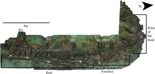
Figure 23. A 3D shaded model produced from the 2017 photogrammetry survey of the exposed structure of the lower hull. R1–4 – riders 1–4, F – frames, FMS – fore mast step (survey and model produced by Daniel Pascoe).
Keel
The exposed surfaces of the keel are in poor condition, due to degradation caused by marine boring organisms and heavy fracturing of the timber. At the forward end where the keel joins the forefoot there is a 410–500 mm space where it appears to have separated from the underside of the frames. This gap increases to 700 mm adjacent to the position of the foremast-step. Due to the general condition, it was not possible to gain accurate dimensions from the visible surfaces of the keel or reliably distinguish between all possible joins and the fractures. The surviving section of the keel is 11.3 m long. At the forward section, where it joins with the forefoot there is 2.13 m (7 ft) long section of rising-wood fastened to the upper surface where the keel joins with the forefoot. The rising-wood has a maximum depth of 200 mm (7.9 in), however more may be buried. This stops in line with the aft end of the foremast-step ( and ).
Forefoot
The forefoot is the foremost piece of the keel and the curved section at the forward end joins onto the lower end of the stem (Boudriot, Citation1986a, p. 79). The visible section of the aft end of the forefoot is 420 mm (16.5 in) moulded and where it curves it increases to 585 mm (23 in). At the forward end is a long plane scarph, which is 1.21 m long (4 ft) ( and ). The aft end has the section of rising-wood as described above fastened to the upper surface.
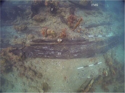
Figure 24. Photo of the forefoot. FF – forefoot, RW – rising-wood, F – frames and FMS foremast-step. The scales in the image are 1 m with 20 cm increments (photo taken in 2022 by Daniel Pascoe).
Knee of the Head
The knee of the head is an assembly of timbers which makes up the head of the ship. It extends forward from the plane of the stem and served to secure the bow sprit and bow decorations (Boudriot, Citation1986b, p. 2). Hazardous’ knee of the head was very prominent when initially discovered but has since deteriorated to the point of it being almost unrecognisable. Fortunately, it was recorded at the time of its first exposure (Owen, Citation1991).
It survived from the level of the gundeck and was visible up to 2 m below that point. The 1991 site drawing identified that the exposed section was constructed from five separate timbers, which include the stem on the inside and the face piece on the outside, the latter consisting of two visible timbers. The space between the two are filled by two other substantial timbers with a near vertical join (). These may be what Boudriot refers to as ‘chocks’ (Boudriot, Citation1986b, p. 8).
Figure 25. The 1991 site plan showing the knee of the head made up of at least five timbers. 1 – stem, 2–3 – chocks and 4–5 – face piece. Other features in plan GD – gundeck, BH – breast hook and FMS – foremast-step (plan © HPG).
Outer Planking and Sheathing
The outer planking is partially visible along the edges of the exposed hull and is generally in a poor condition. At the southern end of the hull structure it is possible to see that the hull below the water line was sheathed with a sacrificial layer of 13 mm (0.5 in) thick fir deals, which was fastened to the outer plank by iron nails. A recovered section identifies that sandwiched between the inside of the sheathing and the outer plank was a layer of animal hair mixed with tar, 10 mm (0.4 in) thick (). The sheathing and tarred hair combined to act as a protective barrier to hinder marine boring organisms from infesting the outer hull planking. A long and straight compression mark within the hair and tar shows that the sheathing overlapped the seams of the main outer planking, thus aiding the unusual lead caulking (described in Owen, Citation1988, p. 292) between the main planks. The overlapping of the main seams appears to be common practice as it was also the method recorded on the wreck of Dartmouth (Martin, Citation1978, p. 50).
Figure 26. The recovered section of outer sheathing. Side 1 is the inside, revealing the layer of tar and hair and side 2 is the outside showing concretion from the iron nail fastenings. The scale is 20 cm (photo by Daniel Pascoe).
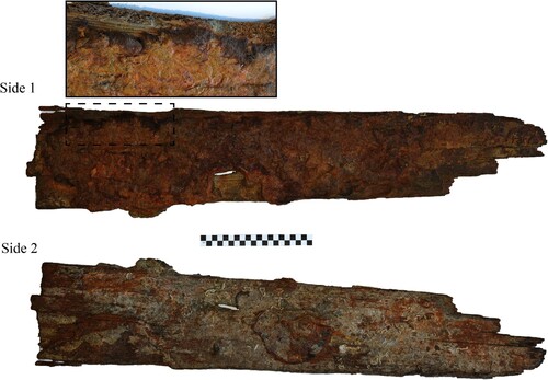
Another interesting feature on the outside of the hull is the presence of a lead tingle between the outer planking and the sheathing, which suggests the condition of the outer planks may not have been in a good state before the sheathing was added (). There is historical evidence to support this as Captain Harris writes to the Admiralty prior to the voyage to Virginia asking that the bottom of the hull should be cleaned as it is very foul. He also states that the carpenters are repairing the doublings, possibly referring to a second layer of planking (TNA, ADM Citation106/Citation609/Citation106).
Figure 27. Photo showing lead tingle between sheathing and outer planks. Scale in photo is 50 cm with 10 cm increments (photo by Daniel Pascoe).
The Spar Site and a Lone 12-Pounder Gun
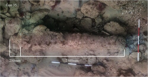
Between 2009 and 2013, while the main site was buried, the team explored the exposed seabed to the north of the site. Sixty metres northwest, a spar and a large double sheaved block with an iron hook was discovered. It is possible that these represent part of the rigging associated with the main or mizzen masts, which were cut away before the ship was run ashore (TNA, ADM Citation52/Citation190). A lone gun was found a further 46 m northwest (gun 35) (). The gun is 2500 mm (8.2 ft) long from end of the muzzle to base-ring and has a bore of 115 mm (4.5 in), which is consistent with a 12-pounder from the upper gundeck ().
Figure 28. Orthophoto mosaic of gun 35, whose size is consistent with a 12-pounder. Scales are 1 m with 20 cm increments (survey and mosaic produced by Daniel Pascoe).
The 2014 Gun Site
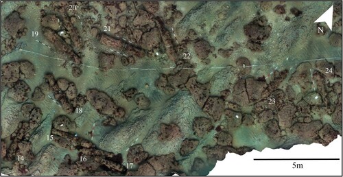
In 2014 the sand had migrated away, uncovering the main site again. This prompted Historic England to contract Wessex Archaeology to conduct geophysical surveys to better understand the full extent of the exposure of the site. The geophysical surveys included multi-beam echo-sounder survey (MBES) over the main site and sidescan sonar and magnetometer surveys over the wider area. The magnetometer survey identified a large magnetic target to the south and the sidescan sonar survey identified several gun-like features within this area (Wessex Archaeology, Citation2015). Diver ground-truthing by the HPG identified 11 guns, a scattering of shot, as well as two lead scuppers. The size of the guns is consistent with the 12-pounders from the upper gundeck and 6-pounders from the quarter and forecastle decks. No wooden structures were found but the presence of lead scuppers suggests structures relating to the side of the vessel did exist at this location at one point. Gun 19 had the partial remains of its carriage, which would suggest these guns were not jettisoned as the carriages would not fit through the gunports. This area of the site was surveyed photogrammetrically in 2019 and is now known as the ‘2014 gun site’ (). Its centre is 125 m to the southwest of the centre of the main site, on the boundary between the southern sand bank and the exposed fossil beds ().
Figure 29. Orthophoto mosaic of the 2014 gun site. Guns numbered 14–24. Scales are 1 m with 20 cm increments (survey and mosaic produced by Daniel Pascoe).
The 2019 Gun Site
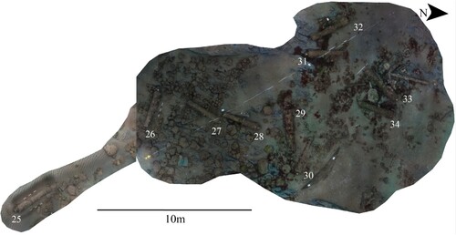
In 2019 the team found a further concentration of 10 guns, this time 120 m northwest of the main site. Among the guns was a high concentration of shot, along with an anchor and other artefacts associated with the ship’s structure, rigging and general shipboard life. The site was surveyed photogrammetrically in 2019, initially nine guns were found and surveyed, followed by a tenth a few weeks later (). This area is now referred to as ‘the 2019 gun site’. The guns in this area are also of a size consistent with the Hazardous’ 12- and 6-pounders.
Figure 30. Orthophoto mosaic of the 2019 gun site. The guns are labelled 25–34. Scales are 1 m with 20 cm increments. Note the scatter of round shot west of guns 26–28 (surveys and mosaics produced by Daniel Pascoe).
Anchor
The survey of Hazardous at Plymouth Dockyard following her capture recorded four anchors, weighing 80 cwt (TNA, ADM Citation106/Citation594/Citation45). This was two less than the requirement for an English fourth-rate (Winfield, Citation2005, p. 98). However, by the time Hazardous was being fitted out for service under the English flag, her new captain, Barrow Harris reported that ‘at her first fitting; as big and capable of mounting 60 guns as one of y 60 gun ships. Her masts, cables, anchors are all y same as theirs’ (TNA, ADM Citation106/Citation586/Citation285).
This appears to suggest that the number of anchors was increased to six. From a near contemporary list and in order of the heaviest Hazardous would have carried a sheet-anchor, spare anchor, best bower, small bower, stream and a kedge (Sutherland, Citation1717, p. 14)
Moving forward to the time of the loss of the ship, we know from the master’s log, that one anchor was cut away to run the ship ashore (TNA, ADM Citation52/Citation190). Due to the distance this anchor would have been from where the ship ended up it is highly likely that this anchor lies somewhere on the seabed some distance south of the site and remains to be located. Later salvage reports described the buoying of two anchors (TNA, ADM Citation106/Citation625/Citation40) and subsequent recovery by 31 March 1707 (NMM, PRO/C/Citation6).
The anchor found on the 2019 gun site is a relatively small anchor. It has an overall length of 2.82 m (9 ft 3 in), a shank length of 2.65 m (8 ft 8 in), a span of 1.8 m (5 ft 11in), and the length of the arm is 0.97 m (3 ft 2 in) (). The wooden stock and iron ring are missing. According to the contemporary draftsman, William Keltridge, the shank length is within 2 in of the appropriate length of a kedge anchor for a fourth-rate (Keltridge, Citation1675, p. 217). The kedge was the smallest anchor carried on board and was small enough to enable it to be carried in the ship’s boat. It was used to work a ship up and down a narrow river or inlet or to pull the ship away from shallow water. The anchor would be lowered into the ship’s boat attached to a long cable, the boat was rowed out to a suitable depth and the anchor dropped. The cable would then be hauled in by the capstan and the ship drawn to a suitable anchorage. This process is known as kedging (Curryer, Citation1999, p. 51; Mainwaring & Perrin, Citation1921, p. 170; Smith, Citation1627, p. 36).
Figure 31. Orthophoto mosaic of the anchor next to guns 33 and 34, HP – Hawse-pipes, SS – sharpening stone and DS – deadeye-strap (survey and mosaic produced by Daniel Pascoe).
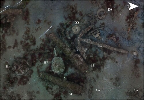
Hawse Pipes
Lying within a few metres of the anchor are two hawse pipes (). The hawse pipes are made of lead and they would have fitted into the hawse-holes, which were cylindrical holes cut through the bow on each side to allow the anchor cables to pass (Falconer, Citation1780, p. 146; Mainwaring & Perrin, Citation1921, p. 161). The draft of Superb identifies that there were two hawse-holes on each side, at the level of the gunports of the lower gundeck. The lead pipes would ensure the cable would not chafe against the edges of the hull. Both pipes have been squashed but the one situated between guns 33 and 34 is the more discernible of the two, showing the two flanges at either end of a flattened pipe. The outer dimeter of the upper flange is 700 mm (27.6 in) and the inner diameter of the tube is 482 mm (19 in). When captured Hazardous had three sizes of cable 20, 18.5 and 12 in (the circumference determines the size of the cable) (TNA, ADM Citation106/Citation594/Citation45). As such, a cable with a circumference of 20 in has a diameter of 6.4 in, so there was plenty of room to work the cables in and out of the hawse-pipes.
In 2020 further migration of sand occurred around the 2019 gun site leading to the burial of eight guns (guns 27–34) and the anchor but exposure of a wider scatter of artefacts west, east and south of gun 26 (). The spread of material included a wide range of artefacts relating to the different aspects of the ship and shipboard activities, such as rigging elements gunnery and small arms, as well as domestic items.
Figure 32. Orthophoto mosaic of the extended area of the 2019 gun site showing a large spread and variety of material which include: CC – copper cauldrons, CP – cast iron pot, DS – deadeye straps and IH – iron hoops. Also scattered among these objects are round and double head shot. Scales are 1 m with 20 cm increments (survey and mosaic produced by Daniel Pascoe).
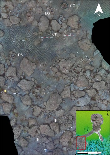
Rigging elements included numerous concreted lower deadeye-straps with chain plates (these will be described in more detail below) and iron hoops, the latter possibly used to secure a composite or made-mast. The English navy preferred to make a mast from a single piece of timber and supply came from either the Baltic or North America (Lavery, Citation1984, p. 83). Major issues with supply did not occur until the 1770s with the American War, which forced dockyards to make masts from several pieces, these were known as made-masts (Boudriot, Citation1987, p. 21; Lavery, Citation1984, p. 83). Initially rope woldings, placed at regular intervals along the mast, were used to help secure all the pieces and these were only replaced by iron bands in the early 1800s (Lavery, Citation1984, p. 84). It wasn’t unusual for made-masts to be used in France, especially for the lower mast, and the French used mast-hoops made from soft Spanish iron to clamp all the pieces together (Boudriot, Citation1987, p. 24). The complete concreted iron hoop on the seabed has an internal diameter of 690 mm (ca. 27.2 in) (). Following Sutherland’s calculations this is only 1 inch wider than the diameter of a foremast for a vessel 38 ft broad and 138 ft along the gundeck, (Sutherland, Citation1717, p. 47). It is therefore not inconceivable that the concreted hoop and other partial hoops are the evidence of Hazardous’ foremast. The other masts were cut down just before the ship was run ashore (TNA, ADM Citation52/Citation190).
There was a variety of domestic items including two large, riveted copper cauldrons, one inside the other and almost identical to examples found on the Cromwellian shipwreck off Duart Point, Scotland (Martin, Citation1995, p. 24; Citation2017, p. 121) and Northumberland wrecked on the Goodwin Sands in 1703 (Pascoe Archaeology, Citation2018). One would assume that these were used in the cook room but the inner cauldron contained a rolled-up trunk of leather inside, suggesting another use. This will be explored in the third article. Other items found were a three-legged cast-iron melting pot, rectangular ingot like weights and several brass measuring weights. As well as a general scatter of round and double headed shot for the great guns there were scatters of lead musket and pistol shot and two concreted muskets.
The anchor, crushed hawse pipes and rigging elements are all suggestive of a major break up of the upper forward parts of the ship structure allowing smaller artefacts associated with that area to spill from the ship.
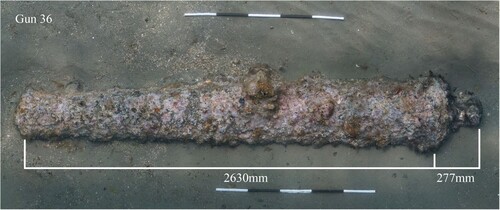
The discovery of the 2019 gun site and the extended area found in 2020 led Historic England to fund another MBES survey for the purpose of mapping the new areas and establishing the location of the sands that impact the site. The survey was directed by MSDS Marine and conducted by Swathe Services with the use of their autonomous vehicle fitted with a hull mounted R2Sonic 2024 ultra-high resolution multibeam. MSDS Marine and Swathe Services did a follow up survey the following year. The results of the surveys identified all exposed areas of the site and enabled the georeferencing of photogrammetric site plans. It also confirmed that the sands to the north had migrated south covering parts of the 2019 gun site and identified several other potential guns that were previously unknown. Diver ground-truthing has confirmed a gun lying just within the designated area, 142 m north-northwest of the main site. This gun has been labelled as Gun 36 and its size is consistent with a 12-pounder ().
Figure 33. Orthophoto mosaics of Gun 36. Scales are 1 m with 20 cm increments (survey and mosaic produced by Daniel Pascoe).
The 2022 Gun Site
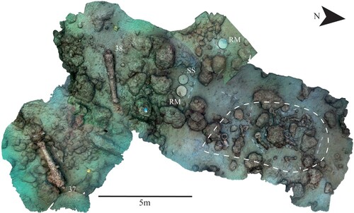
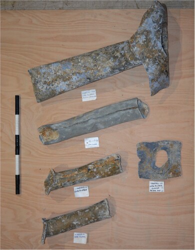
This site lies between the 2014 and 2019 gun sites and consists of a smaller concentration of objects, which had spilled from the ship as it broke up and drifted northwards (). Objects include two probable 6-pounder guns; two halves of a rotary hand mill, used for grinding grain to make bread; and a large circular sharpening stone. A similar and complete rotary hand mill was found on the small Cromwellian shipwreck at Duart Point, within the galley debris, at the port edge of the forward ballast mound. It was suggested that it fell from the forecastle deck where the galley was originally located (Martin, Citation2017, p. 123). The layout of fourth-rates ships also shows that the galley was found in the forecastle, at the forward end of the upper deck (Endsor, Citation2020, p. 273; Winfield, Citation2005, p. 73). As such, the rotary hand mill stones at the 2022 gun site are an indicator of galley material from the forecastle, suggesting the two 6-pounder guns probably originated from the forecastle deck. There is also a jumble of concreted dead eye straps and chain plates and at least two lead scuppers. The dead eye shrouds and chain plates secured the lower end of the mast shrouds, probably the forward mast shrouds, to the outer hull and the scuppers were set into the sides of the hull. Their presence is a good indicator that a fragment of the side of the forward hull broke away from the ship and ended up on the seabed with the guns and other objects. In addition, a trail of iron round and double headed shot litters the seabed between the northwest corner of the 2014 gun site and the 2022 gun site and lead shot lies scattered all around the new area.
Figure 34. Showing a 3D shaded model of the 2022 gun site, also showing the cluster of dead eye shrouds and chain plates plus other objects. RM – rotary hand mill, SS – sharpening stone and deadeye shrouds and chain plates within the dashed area. Scales are 1 m with 20 cm increments and 50 cm with 10 cm increments (surveys and models produced by Daniel Pascoe).
Lower Dead Eye Straps and Chain Plates
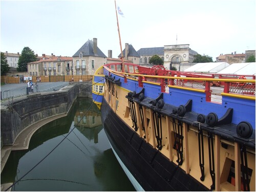
By far the greatest concentration of lower dead eye straps and chain plates have been identified at the 2022 gun site. Dead eye straps were wrought iron bands which were moulded around the lower dead eyes. The lower end of the strap was made into an eye which connected to an iron plate, known as the chain plate or simply the chains (Mainwaring & Perrin, Citation1921, p. 122). Similar examples have been recovered from La Belle (Bruseth et al., Citation2017, pp. 210–13). Chain links were used as an alternative to solid plates as seen on the replica French Frigate L’Hermione. The lower end of the chain plate was fastened to the side of the hull and the upper end was set into the chainwale or channel. The chainwale was a broad timber located on the outside of the ship that acted to spread out the shrouds which were fastened round the upper dead eyes (). The shrouds acted as transverse support for the masts.
Figure 35. Photo of L’ Hermione showing lower deadeye with shrouds and chain plates. The bottoms of the chain plates are bolted to the outside of the hull and the deadeyes are located along the chainwale (photo by Daniel Pascoe).
The lower dead eye straps and chain plates are concentrated in a roughly 6 m by 3 m rectangular area and as such probably originated from one side and one mast location (). There appears to be at least three sizes of dead eye strap 400 mm (16 in), 280 mm (11 in) and 150 mm (6 in) (). The shape of the concretions would suggest the chain plate is of the solid plate variety like those found on La Belle (Bruseth et al., Citation2017, pp. 210–211).
Figure 36. Orthophoto mosaic showing the cluster of deadeye shrouds and chain plates alongside photographs of individual deadeye shrouds and chain plates. Scales are 1 m with 20 cm increments and 50 cm with 10 cm increments (survey, photographs and mosaic produced by Daniel Pascoe).
Lead Scuppers
Lead scuppers allowed water to drain through the sides of the hull from the waterways along the sides of the decks. Several scuppers have been found from across the wreck area and, so far, four have been recovered (). There are variations in their form, and they are all different sizes. Their lengths are a good indicator of the thickness of the hull and can determine which deck above the waterline they were from. The longest scupper (HZ A020-22) has a length of 700 mm (27.6 in), which suggests it most likely passed through inner planking, frame and wale. The wales were located in pairs below and above the main gundeck. Scupper MS-250-99 is 570 mm (22.4 in), which suggests it passed through at main gundeck level but through regular outer planking instead of a wale. Scupper HZ A005-17 is 400 mm (15.7 in) and scupper HZ A013-16 is 365 mm (14.4 in), which suggests locations from the upper gundeck and possibly higher.
Figure 37. Scuppers in order of size from the top down. The scale is 0.5 m with 10 cm increments (photo by Daniel Pascoe).
The most common form of scupper from Hazardous consists of a pipe with a soldered joint running along its length with a circular flange at one end (). Following the evidence from the scuppers recorded from the wreck of the fifth-rate Dartmouth, the soldered joint is located along the upper side of the pipe and the circular flange was located on the outboard side of the hull. The inboard end was fitted with an L-shaped apron, edge-nailed to the waterway and inside of the hull (Martin, Citation1978, p. 52). A detached apron, HZ A006-17, associated with scupper HZ A005-17, shows that the inboard ends were also fitted with an apron, which was originally soldered onto the end of the pipe. It is rectangular rather than L- shaped showing that it was fastened to the side of the hull only (). The scuppers are angled downwards to the outboard flange to allow the free flow of water and leather flapper valves would have been attached to the top of the outer flange to prevent ingress of sea water when the ship rolled or waves struck the hull (Martin, Citation1978, p. 52). The outboard flanges from Hazardous all have nail holes around their circumference showing they were fastened securely to the outer hull planking. The exception is HZ A0020-22, where the inboard apron has no iron nail holes and it appears that it did not have an outboard flange ().
Break up, Salvage and the Sale of the Wreck
The spread of multiple concentrations of guns and other material, linked by debris trails and discovered since 2014, reveals a multi-phased breakup of the ship. This goes some way to explain why only 21 guns were recovered during contemporary salvage operations, despite the wrecking being in shallow water and close to shore. There exist extensive historical records that include the condition assessment of the wreck, shortly after the wrecking; salvage reports; and later documents referring to the sale of the wreck. There are, however, significant time gaps in the reporting of progress and none describe the violent breakup, which caused the loss and dispersal of guns and other material onto the seabed. An early assessment of the condition of the wreck made on 24 November 1706 by the Commissioner of Portsmouth Harbour, Issac Townsend, provides some insight into the challenges of salvaging the wreck:
Yesterday the weather permitting I went on board the Hazardous near Selsey to view her condition, and find her so much down on the larboard side that her gunwale at half ebb, was under water, tis a flatt sand where she lies but the ship is certainly irrecoverably lost, and considering the unlucky place, there is noe coming near her, but in very fair weather and the wind directly from the land, so makes me afraid great part of her stores will be lost too. (TNA, ADM Citation106/Citation614/Citation272)
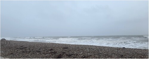
Figure 38. View from East Wittering beach looking out towards the site on the 28 December 2022, showing the condition of the sea during a south westerly (photo taken by Iain Grant).
Lieutenant Hares returned to the ship on 29 November 1706 and reported that it would be possible to save the guns of the upper and quarter decks (HRO, 109 M91C03/40/Citation1706) and progress reports up to 24 January 1707 reveal that some guns were recovered along with the buoying of two anchors (TNA, ADM Citation106/Citation625/Citation40). Anchors tended to be secured along the outside of the bow of the upper deck, thus suggesting that the ship had not broken up by that point. However, the removal of heavy objects, such as anchors and guns, would have lightened the ship and probably contributed to the migration of Hazardous northwards with the subsequent break up and dispersal of material.
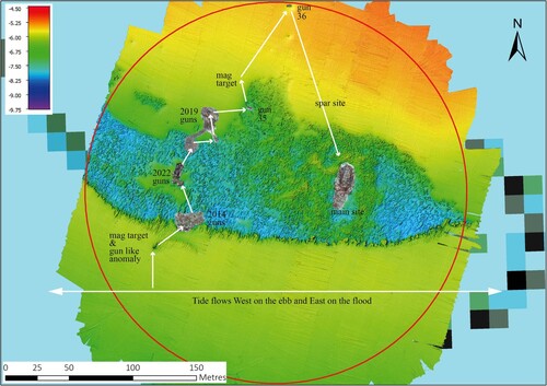
Based on the above archival research and the positioning of archaeology on the seabed, the following is an interpretation of the wrecking process of Hazardous: the likely position of the original condition assessment, as well as the initial recovery of guns and anchors, was likely made close to a location 150 m southwest of the main site and 25 m south-southwest of the 2014 gun site, where a gun like feature, and corresponding magnetic signal, is visible on the bathymetry (). Sometime shortly after 24 January Hazardous started to break up and zig-zagged north with wind and tide, 220 m up to the location of gun 36 – the tide in Bracklesham Bay flows west on the ebb and east on the flood, hence the ship zig zagging east and west as it drifts northwards (). On the way, the upper parts of the hull broke away and spilled guns and equipment from the upper, quarter and forecastle decks; the evidence of which being the 2014, 2019 and 2022 gun sites. Following each loss of heavy objects, the ship would have lightened enough to allow it to be moved with the surf, tide and wind. At the point when the ship reaches the location of gun 36 there was a change in conditions, possibly wind direction coming from the north combined with a flood tide, which moved the surviving part of the ship 130 m southeast, where it comes to rest at the location of the main site (). The current location is most likely the final position of the wreck and where the majority of the salvage took place.
Figure 39. A plot of all the sites georeferenced onto the 2020 bathymetry, showing the suggested direction of travel as the ship breaks up and the direction of the tides in Bracklesham Bay (MBES survey conducted by MSDS Marine and Swathe Services).
By June 1707, records report that only 21 guns had been successfully recovered (TNA, ADM Citation106/Citation625/Citation145), alongside two anchors (NMM POR/C/Citation6) and a general mix of stores and equipment. By September the Navy were keen to put the wreck up for sale as one side of the surviving part of the wreck had parted and washed up on the beach (NMM POR/F/Citation1 and TNA, ADM Citation106/Citation624/Citation212; ADM Citation106/Citation624/Citation216 and ADM Citation106/Citation624/Citation241). On 20 October the surviving hull was sold by inch of candle to the highest bidder, Mr John Day of Emsworth and thus ceased to be the property of the Royal Navy (TNA, ADM Citation106/Citation624/Citation268).
Conclusion
With regards to the surviving hull structure, the combination of natural and targeted excavations, alongside a better understanding of existing data, has led to an improved interpretation of the construction and internal layout of the ship. Hazardous was constructed robustly with a double framing pattern consisting of double floors and futtocks. The double frames with lateral iron fastenings added considerable strength and stiffness to the hull making it more durable to the stresses of sailing, as well as a sturdier gun platform (Batchvarov, Citation2002, pp. 154–155). Double frames, however, were neither a new system nor unique to French construction but one of a few variations in patterns of frames, which is evident from the variations found among the La Hougue shipwrecks (Bruseth et al., Citation2017, p. 99; L’Hour & Veyrat, Citation2000). The evidence from Hazardous and La Hougue wrecks shows that variations in double framing co-existed in France during the end of the 17th century and beginning of the 18th-century. The evidence from the later wreck of Invincible (1744–58) suggests that the double floor and futtock system became the norm during the 18th century.
Other similarities with Invincible can be seen in the construction of the foremast-step, which also matches Boudriot’s reconstruction of a foremast-step for a French 74-gun ship, suggesting this is typical of French construction. However, without a comparison from an English/British built ship it is difficult to know whether there were differences.
The distribution of artefacts found on the main site suggests the internal arrangement of stores and cabins were altered to suit the English layout and organisation. As such, the main magazine was moved to the forward end of the hold, as opposed to the aft end. The carpenter’s, boatswain’s and gunner’s stores were located on the forward platform deck. The altering of internal space can also be seen throughout the wreck of Invincible (Bingeman, Citation2010; personal observations from the 2017–19 excavations) and was an obvious way to maintain familiarity and efficiency in the management and operation of the ship.
Finally, the discovery of the multiple gun sites has not only transformed the understanding of our wrecking and site formation process, but the other artefacts found within them has provided a wealth of information relating to all aspect of shipboard life and culture; this will be the focus of subsequent papers.
Permission Statement
The wreck of Hazardous is legally protected by designation under the Protection of Wrecks Act (1973). This designates an area around the wreck site within which any intrusive activity requires a licence from the Secretary of State at the Department of Culture, Media and Sport, administered by Historic England (HE). All work described in this manuscript has been undertaken under the annual licencing and reporting requirements of the PoWA (1973) and to workplans and formal project designs agreed with HE (for unfunded and HE grant-funded activities respectively). All additional, non-archaeological permissions, licences and permits required for the archaeological investigations (Crown Estate, as seabed owner) and Marine Management Organisation (as licensor for seabed activities of all kinds) were also obtained prior to the commencement of the activities. All archaeological material recovered from the seabed has been reported to the Receiver of Wreck as required under the Merchant Shipping Act.
The Hazardous Project Group is in regular liaison with HE as much work in recent years has been reactive mode, due to ever-changing seabed conditions. Ongoing reports and updates on project activities are reported on the group’s wwwsite (www.hazardous project.info), as are copies of formal annual reports to HE.
Conservation of raised artefacts is funded by HE. The HPG used to have its own museum, open to the public, but this was forced to close when the land owners sold up. Artefacts are currently in storage whilst agreements for their long term transfer to the National Museum of the Royal Navy (Portsmouth) are formalised.
Acknowledgments
This paper is a culmination of over 30 years of (ongoing) work by a dedicated team of professional and avocational archaeologists, divers and researchers, who have given so much of their free time and finances to ensure as much information as possible has been recorded before it was lost to natural processes. A special mention must go to the members of the original 308 branch of the Sub Aqua Association and to past and present members of the HPG. The HPG would also like to thank the National Lottery Awards, and, most recently, Historic England for funding, which has contributed to recent site monitoring, investigations and reporting, as well as the costs of the conservation of recovered material.
Author Contributions
Study design: all authors. Fieldwork: all authors. Data interpretation: all authors. Manuscript writing: Daniel Pascoe. Comments on manuscript: Dave Johnston and Iain Grant.
Disclosure Statement
No potential conflict of interest was reported by the author(s).
Additional information
Funding
References
- Batchvarov, K. N. (2002). The framing of seventeenth-century men-of-war in England and other northern European countries [Unpublished PhD thesis]. Texas A&M University. Retrieved June 30, 2023, from https://hdl.handle.net/1969.1/ETD-TAMU-2002-THESIS-B387
- Bingeman, J. (2010). The first HMS invincible (1747–58) her excavations (1980–1991). Oxbow Books.
- Boudriot, J. (1986a). The seventy-four gunship. Volume 1: Hull construction. Jean Boudroit Publications.
- Boudriot, J. (1986b). The seventy-four gunship. Volume 2: Fitting Out The hull. Jean Boudriot publications.
- Boudriot, J. (1987). The seventy-four Gun ship. Volume 3: Masts – Sails – Rigging. Jean Boudriot publications.
- Browning, O. (1897). The journal of Sir George Rooke Admiral of the Fleet 1700–1702. Navy Records Society.
- Bruseth, J. E., Borgens, A. A., Jones, B. M., & Ray, E. D. (2017). La Belle the archaeology of a seventeenth-century ship of new world colonization. Texas A&M University Press.
- Calmon-Maison, R. (1903). Le maréchal de Château-Renault (1637–1716) (20th ed.). Hachette Livre.
- Curryer, B. N. (1999). Anchors an illustrated history. Chatham Publishing.
- Defoe, D. (1704). R. Hamblyn (Ed.), The storm (2005th ed.). Penguin Books Ltd.
- Endsor, R. (2009). The restoration warship. Conway.
- Endsor, R. (2017). The warship Anne. Conway Bloomsbury.
- Endsor, R. (2020). The master shipwright’s secrets. Osprey Publishing Ltd.
- Falconer, W. (1780). Falconer’s marine dictionary (1780). T. Cadwell.
- Hampshire and Wight Trust For Maritime Archaeology. (2006). Quantifying the Hazardous threat: An assessment of site monitoring data and environmental data sets. Southampton. Retrieved June 30, 2023, from https://www.academia.edu/5813046
- Keltridge, W. (1675). Book of William Keltridge, 1675, Containingh dimensions of HM Ships, materials required, stores, pay, etc.
- Lavery, B. (1981). Dean’s doctrine of naval architecture, 1670. Conway Maritime Press.
- Lavery, B. (1984). The ship of the line volume II: Design, construction and fittings. Conway Maritime Press.
- L’Hour, M., & Veyrat, E. (1999). Les épaves de la Hougue (1692) : Une base de données pour l'étude de la Marine royale française. In C. Villain-Gandossi (Ed.), Deux siecles de constructions et chantiers navals, millieu XVlle – millieu XlXe siecle. Actes du 124e congres national des societes historiques et scientifiques, Nantes (pp. 135–146). Nantes.
- L’Hour, M., & Veyrat, E. (2000). La fouille des épaves de la Hougue, dans DRASSM, Recherches Sous–Marines, DRASSM 1991–1995. Gallia informations (pp. 1–17). CNRS. CDRom.
- Mainwaring, G. E., & Perrin, W. G. (1921). The life and works of Sir Henry Mainwaring, Vol. II. Navy Records Society.
- Martin, C. J. M. (1978). The Dartmouth, a British frigate wrecked off mull, 1690. 5. The ship. The International Journal of Nautical Archaeology and Underwater Exploration, 7(1), 29–58. https://doi.org/10.1111/j.1095-9270.1978.tb01044.x
- Martin, C. J. M. (1995). The Cromwellian shipwreck off Duart Point, Mull: An interim report. The International Journal of Nautical Archaeology, 24(1), 15–32. https://doi.org/10.1111/j.1095-9270.1995.tb00708.x
- Martin, C. J. M. (2017). A Cromwellian warship wrecked off Duart Castle, Mull, Scotland, in 1653. Society of Antiquaries of Scotland.
- Owen, N. C. (1988). HMS Hazardous wrecked 1706. Pre-disturbance survey report 1987. International of Nautical Archaeology and Underwater Exploration, 17(4), 285–293. https://doi.org/10.1111/j.1095-9270.1988.tb00659.x
- Owen, N. C. (1991). Hazardous 1990–1991 interim report. International Journal of Nautical Archaeology, 20(4), 325–334. https://doi.org/10.1111/j.1095-9270.1991.tb00328.x
- Pascoe Archaeology. (2018). Archaeological assessment of the designated wreck of the Northumberland on the Goodwin Sands. Retrieved June 30, 2023, from https://historicengland.org.uk/research/results/reports/242-2020
- Pascoe, D., & Peacock, R. (2015). The wreck of the warship Northumberland on the Goodwin Sands, England, 1703: An interim report. International Journal of Nautical Archaeology, 44(1), 132–144. https://doi.org/10.1111/1095-9270.12074
- Smith, J. (1627). K. Goell (Ed.), A sea grammar. Michael Joseph Ltd.
- Steel, D. (1796). The art of rigging. David Steel.
- Sutherland, W. (1717). Britain’s glory: Or, ship-building unveil’d. Being a general director, for building and compleating the said machines. London.
- Wessex Archaeology. (2015). Archaeological services in Relation to marine designation Hazardous. Marine geophysical survey report. Salisbury.
- Whitewright, J. (Ed.) (2020). The Stirling Castle, a 70-gun ship lost in the great storm of 1703. Archaeological investigations 1979–2009. BAR Publishing.
- Winfield, R. (2005). The 50-gunship complete history. Mercury Books.
- Winfield, R. (2009). British warships in the Age of Sail 1603–1714 design, construction, careers and fates. Seaforth publishing.
- Winfield, R., & Roberts, S. (2017). French warships in the Age of Sail 1626–1786. Design, construction, careers and fates. Seaforth publishing.
Primary Documents
- HRO. (109M91 C03/40/1706). Lieutenant Hares reports removing small arms from the Hazardous, 29th November 1706. Hampshire County Council Archives.
- NMM. (POR/C/6). Commissioners warrants reporting from the wreck of the Hazardous, March 1707. The National Maritime Museum.
- NMM. (POR/F/1). Letters to the Navy Board reporting of the condition of the Hazardous. The National Maritime Museum.
- TNA. (ADM 51/4217). Captain’s log Hazardous (1704 6th May to 1706 19th Feb). The National Archives.
- TNA. (ADM 52/190). Master’s log for the Hazardous (1706 18th Sept to 1706 19th Nov). The National Archives.
- TNA. (ADM 106/586/285). Letter from Captain Harris, getting the ship ready, 24th December 1704. The National Archives.
- TNA. (ADM 106/594/45). Report of the survey of the Hazardous Prize, 19th March 1704. The National Archives.
- TNA. (ADM 106/609/106). Letter from Captain Harris reporting work done on the ship, 5th February 1705. The National Archives.
- TNA. (ADM 106/614/272). Report the Hazardous is irrecoverably lost, 24th November 1706. The National Archives.
- TNA. (ADM 106/624/212). An order to dispose of the wreck of Hazardous, 11th September 1707. The National Archives.
- TNA. (ADM 106/624/216). The Hazardous to be put up for sale, 15th September 1707. The National Archives.
- TNA. (ADM 106/624/241). The Hazardous to be advertised for sale, 6th October 1707. The National Archives.
- TNA. (ADM 106/624/268). Report of the sale of Hazardous to John Day, 20th October 1707. The National Archives.
- TNA. (ADM 106/625/40). Report on the Hazardous wreck, 24th January 1707. The National Archives.
- TNA. (ADM 106/625/144). Letter from Commissioner Townsend reporting removing guns from the Hazardous, 8th June 1707. The National Archives.
- TNA. (ADM 106/625/145). Report of the removal of 21 guns from the Hazardous, 6th June 1707. The National Archives.
- TNA. (HCA 32/62/35). Captured ship: Le Hazardous de Port Louis, 1703. The National Archives.
- TNA. (WO55/1650). Particulars of stores and arms on board one ship of every rate, 1677–78. The National Archives.