 ?Mathematical formulae have been encoded as MathML and are displayed in this HTML version using MathJax in order to improve their display. Uncheck the box to turn MathJax off. This feature requires Javascript. Click on a formula to zoom.
ABSTRACT
The forelock bolt was a ubiquitous joining technology employed by ancient shipwrights. Its systematic positioning in the Serçe Limanı ship (11th century CE) was the primary joining technology of its keelson-frames-keel assembly. This fact lends itself well to analyzing its engineering-technical properties, which were identical to those of modern bolts. The preload required to apply secure clamping force in the Serçe Limanı keelson-frames-keel backbone assemblage, was analyzed applying the physics of bolt technology. A structural Finite Element Analysis (FEA) was conducted on the bolt and, under laboratory conditions, was validated on a physical model. It was thus demonstrated that the bolt achieved the conditions needed to securely fasten the Serçe Limanı keel assemblage while serving as a means of efficient structural maintenance.
RESUMEN
El perno con chaveta fue una tecnología de unión muy común empleada por antiguos astilleros. Su colocación sistemática en la embarcación SerçeLimanı (siglo XI EC) fue la principal tecnología de unión del conjunto sobrequilla-cuadernas-quilla. Este hecho se presta bien al análisis de las propiedades técnico-ingenieriles, que eran idénticas a las de los pernos modernos. Se analizó la precarga requerida para aplicar una fuerza de sujeción segura en el conjunto vertebral de sobrequilla-cuadernas-quilla de SerçeLimanı aplicando la física de la tecnología de pernos. Se realizó en el perno un análisis estructural por elementos finitos (FEA, por sus siglas en inglés) y, bajo condiciones de laboratorio, fue validado a través de un modelo físico. Por ende, se demostró que el perno logra las condiciones necesarias para sujetar con seguridad el conjunto de la quilla de SerçeLimanı, mientras sirve también como un medio de mantenimiento estructural eficiente.
摘要
楔栓键是古代船工普遍采用的连接技术。它在塞尔塞利马尼 (Serçe Limanı) 沉船(公元11世纪)中的系统定位是内龙骨-框架-龙骨结构的主要连接方法。这一事实非常适合分析其工程技术特性,这些特性与现代螺栓的特性相同。我们使用应用螺栓技术的物理原理对在塞尔塞利马尼沉船内龙骨-框架-龙骨骨干结构中施加安全夹紧力所需的预紧力进行了分析,并对楔栓键进行结构有限元分析 (FEA),也在实验室条件下在物理模型上进行了验证。结果表明,该楔栓键满足了安全固定塞尔塞利马尼沉船龙骨结构所需的条件,同时也可作为一种有效的结构维护手段。
摘要
楔栓鍵是古代船工普遍采用的連接技術。它在塞爾塞利馬尼 (Serçe Limanı) 沉船(公元11世紀)中的系統定位是內龍骨-框架-龍骨結構的主要連接方法。這一事實非常適合分析其工程技術特性,這些特性與現代螺栓的特性相同。我們使用應用螺栓技術的物理原理對在塞爾塞利馬尼沈船內龍骨-框架-龍骨骨幹結構中施加安全夾緊力所需的預緊力進行了分析,並對楔栓鍵進行結構有限元分析 (FEA),也在實驗室條件下在物理模型上進行了驗證。結果表明,該楔栓鍵滿足了安全固定塞爾塞利馬尼沈船龍骨結構所需的條件,同時也可作為一種有效的結構維護手段。
القديمة
المُستخلص
كان المِزلاج الأمامي عبارة عن تقنية ربط قام باستخدمها صانعو السفن القدماء بشكل واسع الانتشار. كان وضعه المنهجي في سفينة ميناء سبارو (القرن الحادي عشر الميلادي) كتقنية ربط أساسية لتجميع الهيكل الذي يمتد بطول السفينة بالعارضة و بالأخشاب الخاصة بالأرضية. هذه الحقيقة مناسبة لتحليل خصائصه الهندسية والتقنية، والتي كانت مماثلة لتلك الخاصة بالمَزَالِيج الحديثة. تم القيام بعمل تحليل للتحميل المُسبق المطلوب لتطبيق قوة تثبيت آمنة في مجموعة العمود الفقري ذات الهيكل الذي يمتد بطول السفينة ويربط العارضة بالأخشاب الخاصة بالأرضية في سفينة ميناء سبارو، وذلك باستخدام فيزياء تكنولوجيا المَزَالِيج. ولقد تم إجراء تحليل العناصر المحدودة الهيكلية (FEA) على المِزلاج، وفي ظل ظروف المختبر، تم التحقق من صحته على نموذج مادي. ومن ثَم، تم إثبات أن المِزلاج قد حقق المتطلبات اللازمة لتثبيت مجموعة العارضة بشكل آمن في سفينة ميناء سبارو وهذا أثناء العمل كوسيلة للصيانة الهيكلية الفعالة.
PALABRAS CLAVES:
Introduction
The forelock bolt was a robust and ubiquitous fastener of large wooden beams installed by shipwrights from Graeco-Roman times until the 19th century (McCarthy, Citation2005, p. 69). This article is the mechanical analysis of the forelock bolt and its usage, using that from the 11th century Serçe Limanı merchant ship as a model. This article is derived from a broader research dissertation on exploring the marine architectural-archaeological essences of the keelson in the Serçe Limanı ship in the context of structural transition. The larger study demonstrated that the keelson itself did not contribute to the longitudinal reinforcement of the hull. It was shown, however, that its presence served as an efficient aid to manufacturing and maintenance, while indirectly contributing to the navigational capacity of the vessel (Helfman, Citation2023). The complexity of demonstrating the above-mentioned conclusion is beyond the scope of this article.
The Serçe Limanı ship, discovered in a bay called the Serçe Limanı, southwest coast of Türkiye, opposite Rhodes, and dated to 1025 CE (Pomey et al., Citation2012, p. 287), exhibited an innovative usage of forelock bolts which joined the keelson, frames and keel, generally at five-frame intervals. This fastening technology had its own structural integrity which contributed significantly to the overall integrity of the hull, thereby making it worthy of isolated mechanical analysis. The keelson was an 18-cm thick un-notched timber, resting flush upon the frames from stem to stern. This was a unique frame-based innovation differentiating it from earlier notched central timbers which were nailed to the frames, as exemplified by the notched keelson of the Tantura B shipwreck (9th century CE), discovered at Dor Lagoon, Israel. Earlier frame-based vessels such as the Tantura A (5th century CE) and the Dor 2001/1 (6th century CE) (Pomey et al., Citation2012), both also discovered at Dor Lagoon, did not possess a keelson, and were fitted with longitudinal timbers which served as either amidships mast-steps or stem-to-stern reinforcements. A full-length keelson similar to that of the Serçe Limanı was also absent in shell-first shipwrecks, such as the Kyrenia (4th century BCE), discovered off the northern coast of Cyprus and the La Madrague de Giens (2nd century BCE), discovered off the Mediterranean coast France (Pomey et al., Citation2012).
In general, the purpose of a joint is to transmit forces to hold members together by means of compression forces, using some form of fastener (Yeomans, Citation2020, p. 33). This applies to nails, screws, bolts, and in this case, the forelock bolt. The forelock joining bolt was alternatively known as a ‘wedge bolt’ with a ‘key’, ‘tongue’ or ‘gib’ or ‘cotter pin’. J. R. Steffy defined the forelock bolt as ‘an iron bolt with a head on one end and a narrow slot at the other; secured by placing a washer over its protruding end and driving a flat wedge, called a forelock, into the slot’ (Steffy, Citation1994, p. 271). This describes the characteristic forelock bolt of the Serçe Limanı ship (). Forelock bolts were inserted into pre-drilled pilot holes, a practice which is implemented in modern threaded bolt joints. The pilot holes were drilled to a larger diameter than the bolts to allow easy initial assembly, and rapid disassembly and re-assembly in effecting repairs (McCarthy, Citation2005, p. 70), especially to the keel. The bolting technology is the preferred fastening method where maintenance can be carried out without causing unwanted damage. Maintenance and repair of nailed joints would tend to be destructive. This bolting practice is echoed, for example, in the modern railway industry, where bolted joints are applied to ensure efficient maintenance and repair (Denkert et al., Citation2019).
Figure 1. Forelock bolt with wedge and ring (adapted based on McCarthy, Citation2005, fig. 42, p. 70. Reproduced with permission).
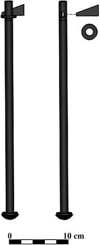
The Serçe Limanı forelock bolts were produced from iron (Steffy, Citation1982, p. 20). Though a metallurgical analysis was never conducted on the forelock bolts due to extensive concretion, structural analysis conducted by Finite Element Analysis (FEA) requires precise mechanical properties, particularly tensile strength. Hence the choice was made, based on M. McCarthy (Citation2005, p. 90) who described ‘hand-forged wrought nail survived in wooden shipbuilding […] into the nineteenth century’. The assumption of cast iron was rejected, as it is brittle and less malleable, making it less suited for structural components under tension (O'Sullivan & Swailes, Citation2009, pp. 261, 267; Sadegh & Worek, Citation2018, p. 206). The bolts averaged 2 cm in diameter and 40 cm in length. They were apparently intended to be spaced at every fifth floor, although there were some irregularities. They were inserted from beneath the keel, recessed, doubled over the keel scarfs, and locked with forelocks on the upper surface of the keelson. The washer, about 3.5 cm in diameter, served to prevent the forelock’s penetration into the upper surface of the keelson while distributing the force over the surface area (Steffy, Citation2004, p. 164).
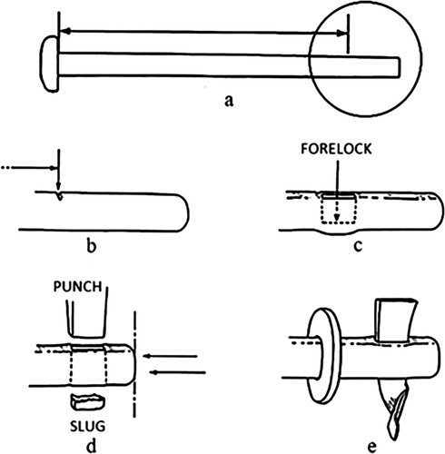
J. D. Light (Citation2000, p. 331) described the ‘customized’ production of forelock bolts used in 16th century wooden vessels. The smithing and delivery methods of the wrought iron forelock bolts used in both the construction of the 11th century Serçe Limanı ship and 16th century vessels, would conceivably be similar. The head of the bolt was fashioned before the bolt arrived at the shipyard. The exact length of the pilot hole through the jointed planks, floor timbers or assemblages was unknown: each hole had a different length. Hence, a bolt was customized by initially inserting it with its head flush to one side of the joined pieces. After a cold chisel indentation was made on the bolt corresponding to the length of the pilot hole at the opposite side of the joint, the bolt was cut short near the end of the hole. A slot was then punched for hammering the forelock into place. The forelock was then twisted to lock it (Light, Citation2000, p. 332) ().
Figure 2. The manufacture of the forelock bolt: a) the bolt is measured; b) a cold chisel mark is made on the bolt; c) a hole is punched with a rectangular punch d) the bolt is cut off near the hole; e) the forelock is inserted and twisted to lock it in place (Light, Citation2000, p. 332, fig. 6. Reproduced with permission).
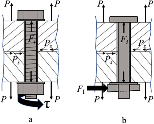
The force-stress regimes of the forelock bolt and modern threaded bolt are almost identical: they must both achieve sufficient ‘preload’, relying on friction generated between two surfaces. The effect of preload is to tighten the bolts, thereby placing the bolted member components in compression for better resistance to the external tensile load, and to create a friction force between the parts to resist shear load (Shigley et al., Citation2004, p. 301). Deutsches Institut für Normung, which is the German institute for standardization, defines a bolted joint as follows: ‘A bolted joint has the task of joining components in such a way that the appearance of slippage or widening the gap are prevented’ (DIN 25201-Citation2, Citation2015, pp. 1–36). When the forelock is hammered into the slot, a tensile stress is achieved equivalent to the threaded bolt shank when applying a torque on the tightening nut. The forelock, a wrought iron wedge a few millimetres thick, is equivalent to the frictional surfaces of the helical inclined plane of the winding threads. The comparative systems of applying preload properties to the modern threaded bolt and to the forelock bolt are illustrated in . The bolting efficacy of the forelock bolt employed in the Serçe Limanı keel-frames-keelson assembly configuration can only be measured by its capacity to prevent slippage between the keelson, the frames and the keel.
Figure 3. Comparing preloads of a threaded bolt to the forelock bolt: a) modern threaded bolt; b) forelock bolt. Fi = preload; P = external load; Ps = shear load; FI = impact force on the forelock; and τ = torque (illustration: N. Helfman).
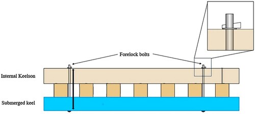
Future research could resolve a seemingly contradictory phenomenon: the resulting radial and tangential expansion of the keel due to absorbed moisture content (MC) should theoretically enhance preload at the keelson-frames-keel assemblage contacts (). However, mechanical properties, specifically the module of elasticity (MOE), tensile strength and compressive strength, vary inversely with the moisture content up to the fibre saturation point (Güntekin & Aydin, Citation2013, p. 878).
Figure 4. Schematic forelock installation of Serçe Limanı ship (illustration: N. Helfman).
Methods and Materials
The mechanical analysis of the forelock bolt was designed to measure to what degree this clamping device developed a preload which ensured the rigidity of the keelson-frames-keel assemblage, effectively forming an ‘I-beam’ () longitudinal reinforcement. The simulated fastener was a wrought iron bolt where the longitudinal tension was developed by impact force upon an inclined plane (wedge) and held in place by friction. As such, it bore close resemblance to the modern spiral-threaded bolt system, which also achieves its clamping load tension through frictional forces between metal surfaces of an inclined plane.
Figure 5. a) I-beam; b) Serçe Limanı section of keel-frames-keelson assemblage (illustration: N. Helfman).
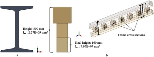
Because of the absence of both precise specifications and mechanical data about the forelock bolts employed in the Serçe Limanı ship, the inquiry required the application of a mathematical model based solely on archaeological documentation of materials and geometric dimensions of the bolt shank. There are no dimensional data on the wedge. The determination of force regimes applies the methodologies of modern physics and engineering principles, which also drove the implementation of an FEA model and the construction of a physical validation model.
Recalling the method of installing the forelock bolt (Steffy, Citation2004), the wrought iron bolts were inserted from the underside of the keel through pilot-holes, which were drilled with a clearance fit to accommodate their 2 cm diameter. The 40-cm-long bolts were distributed approximately at every fifth frame and were doubled at keel scarfs. Washers were fitted both between the bolt head and the keel, and between the forelock and the keelson. The forelock was hammered into the slot, bent, and held in place with two nails (Steffy, Citation1982, p. 20).
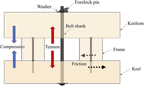
The longitudinal tension maintained by the forelock creates the compression between the bolted members, hence establishing preload. The preload thereby resists external tension and creates friction between the compressed members, thus reducing slippage between them (Shigley et al., Citation2004, p. 301). The friction force between two solids is proportional to the force linking them together; therefore, all these bolting conditions must exist, as assembled in the Serçe Limanı keelson-frames-keel assemblage to satisfy the conditions of a single stiffened longitudinal reinforcement ().
Figure 6. Transparent keelson-frames-keel section demonstrating preload induced by secured forelock bolt (illustration: N. Helfman).
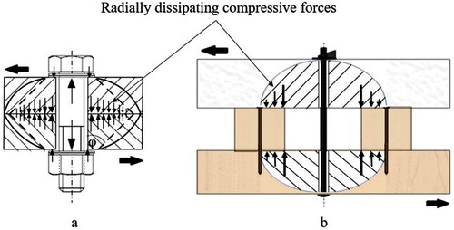
Calculating the preload of the Serçe Limanı forelock bolts is essential in evaluating the overall rigidity of the assemblage. These results must also be considered in the context of bolts at five-frame intervals. In this configuration, with the radial dissipation of the stress field, shown in the ‘idealised’ illustration (), the bolt is centred between the frames, and at best, only one-half of the potential preload acts on each of the frames on its sides. The archaeological evidence demonstrates a more random inter-frame distribution. There was a remarkable paucity of nails fastening the keelson to the frames, although indirect evidence was revealed at the stem-apron-keelson junction. Other isolated nails secured the bolt washers; a nail penetrated from the keelson to a frame leaving no head impression (nail D, frame 9); nail penetration from the keelson but did not exit the bottom of the timber (nail E); and a 5-cm-long nail running athwartships from the port surface of the keelson (nail F) (Mathews & Steffy, Citation2004, p. 116). One could speculate that nail E served as a centring fixture when mounting the keelson prior to bolting.
Figure 7. Radially dissipating preload: a) Preload generated from conventional nut and bolt configuration (Denkert et al., Citation2019, fig. 1, p. 2); b) Serçe Limanı between-frame forelock bolt configuration showing reduction of potential preload (illustration: N. Helfman).
A daunting methodology limitation and potential source of error in research of this nature is nature itself: the properties of wood. Wood is anisotropic – possessing different physical properties in different directions. This required meticulous determination of each wood-type’s tangential, radial, and longitudinal mechanical property values. Hence, prior to launching the FEA software, the corresponding mechanical properties were adjusted. Under the validation laboratory conditions, timber moisture content varied en route to the laboratory site at the Israel National Building Research Institute, and at the site itself, requiring measuring, recording, and updating the CAD software.
The methodology employed to evaluate the forelock fastener combines basic analytical equations with FEA. The following is an exposition of the mathematical model and FEA analysis. The generic stress-strain graph presents the relative strengths in the ranges above and below preload ():
Calculation of the preload (Fi).
The bolt displacement resulting, hence the indicator of efficacy.
Calculation of the force impacting on the forelock to cause the bolt elongation.
Application of the calculated force on the forelock in an FEA simulation.
Figure 8. Generic preload stress-strain diagram for bolt materials: Sp = proof strength; Sy = yield strength; Sut = tensile strength (adapted from Shigley et al., 2004, fig. 8–13, p. 312).
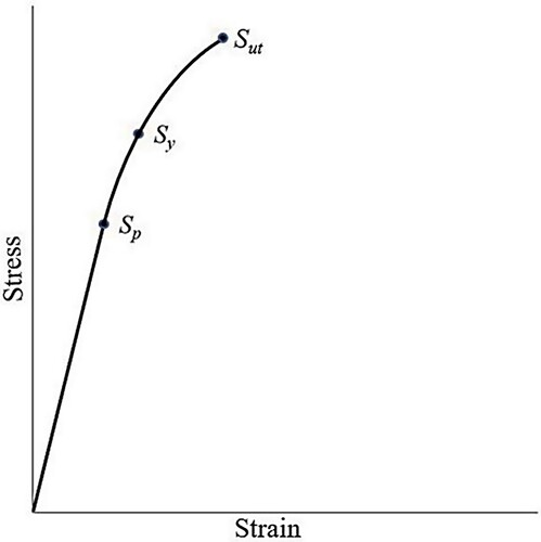
Prior to calculating the preload, the proof load must be derived, which represents the usable strength range for the fastener. The proof load is composed of a proof strength (Sp) or ‘usable strength’. This is the upper limit of the bolt strength which can be used without deformation, i.e., remains ‘elastic’. In general terms, proof strength is typically 85–95% of the yield strength (Shigley et al., Citation2004, p. 312), the point where permanent deformation begins (the beginning of the ‘plastic range’) (Sy). It is crucial that the bolts are not loaded into their plastic regime. Assuming the yield point of wrought iron is ≈ 250 N/mm2 (O'Sullivan & Swailes, Citation2009, p. 269), we can calculate the proof strength as 90% of the yield strength (Sp):
(1)
(1)
The proof load of each bolt is given by:
(2)
(2) where
= Proof load,
= active thread cross-section (20 mm2 of forelock bolt)
(3)
(3)
(4)
(4)
The preload, or Fi, is calculated for the forelock bolt:
(5)
(5)
(6)
(6)
The preload, Fi, is directly proportional to the displacement, δ, of the tensioned bolt, and is given by:
(7)
(7) where δ = displacement, A = active thread cross-section, E = module of elasticity, l = length. Hence, in rearranging the equation and isolating the δ, the efficacy of the preload can be determined by evaluating the displacement:
(8)
(8)
Calculation of δ:
(9)
(9) Thus, if the displacement averages more than 0.44 mm along the sampled length of the forelock bolt, it can be assumed that the bolt is satisfactorily preloaded (Shigley et al., Citation2004, p. 306).
The source of the tension in the length of the bolt is the wedge or forelock. The forelock, generating normal forces (N) at the areas of contact of the slot, resisting friction (μ = 0.2) forces, progressively tensions the bolt as it is hammered (P) into the slot ().
Figure 9. Generic wedge forces diagram where Nn = normal force, P = force applied, fn = friction forces, μ = friction coefficient, and θ = angle of inclination (illustration: N. Helfman).
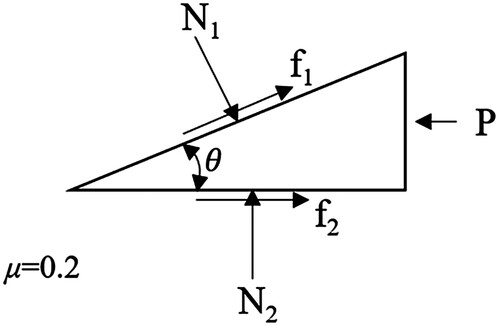
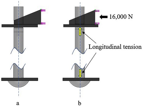
Figure 10. Forelock bolt mechanism: a) before wedge insertion; b) after insertion (illustration: N. Helfman).
Hence, the stresses and displacements developed in the length of the bolt are the result of the work (W) done by the hammer impacting the wedge. Work, which is otherwise kinetic energy (KE) (), can be interpreted as force × distance (Fd), which ultimately can be translated into the force on impact:
(10)
(10)
Applying the energy equation, the calculated impact force of a hammer weighing 1.5 kg at a velocity of 8.0 m/s driving the wedge 4 mm (d) is about 16,000 N 4 mm insertion of forelock). This force value was inserted into the FEA forelock bolt simulation program as a 1 mm increment parameter which was increased with each FEA run. Stress, displacement, and strain were recorded and graphed; see below.
FEA Methodology and Validation
With the intent of substantiating that the FEA simulations indeed reflect physical reality, mechanical engineering research applies a discipline known as ‘verification and validation’. The process ensures that the computerized model is appropriate and is consistent with the intended application (Schlesinger, Citation1979, p. 103).
Finite element analysis (FEA) is a mathematical idealization of physical and structural behaviour – an engineering analysis. As a mathematical model, it is subject to verification to ascertain the model’s mathematical veracity. Validation, on the other hand, deals with the accuracy of physical models tested in a controlled laboratory environment. Validation is rooted in epistemology and is required in research to justify knowledge claims (Barth et al., Citation2011, p. 3).
A set of equations was used to derive the preload, which led to the characteristic displacement (δ) of the forelock bolts which would maximize the clamping of the keelson-frames-keel assemblage. These results were assimilated to the application of FEA.
An FEA scenario was thus developed with the objective of ascertaining whether the mechanics of the forelock bolt (as interpreted by the authors) would suffice to develop the required preload in order to maintain rigidity of the assemblage. The simulation involved creating a constraint where the washers were ‘virtually’ adjacent to the beams. Four simulations were run which incrementally increased the insertion by 1 mm, i.e., 1–4 mm.
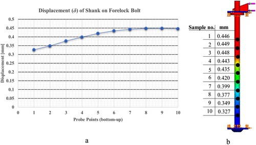
illustrates the 4 mm run. Each blue point on the bolt shank (left) represents a sample point. The sample field length of the bolt shank represented the range on the bolt where displacement values were at their relative highest. On all the four runs, three measurements on each sample point were taken and then averaged.
Figure 11. Displacement (δ) of shank of forelock bolt: a) probe points on shank vs. displacement results; b) displacement distribution representation (illustration: N. Helfman).
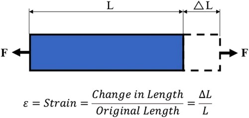
The validation methodology employed for the forelock bolt comprises a mathematical verification (Eqs. 1–9), an FEA simulation, and a physical laboratory model test. An FEA sampling method was devised such that by varying the distance of insertion of the forelock, displacement values of the bolt could be deduced. When subjecting a bar to tensile loads, it becomes longer. The ratio of the change in elongation length to the original length is known as strain (ϵ) (Shigley et al., Citation2004, p. 36). The displacement (δ) value was essential in comparing FEA and laboratory results, which were generated in terms of microstrains (μϵ), that is, ϵ × 10−6. illustrates the concept, where: F = force, L = original length, ΔL = change in length. The mathematical relationship between the preload (P) and the strain (ϵ) is essential in determining the efficacy of the forelock bolt in ensuring the rigidity of the keelson-frames-keel assemblage.
Figure 12. Strain – the ratio of the elongation change to the original length (illustration: N. Helfman).
Determining the strain value is pivotal in validating the FEA simulations. The mathematical relationship between strain (ϵ) and preload (Fi) where δ = 0.44 mm is the elongation of the bolt due to the forelock insertion (at 4 mm insertion of forelock), determines the efficacy of the forelock bolt in ensuring the rigidity of the keelson-frames-keel assemblage, and is expressed in the following equation:
(11)
(11)
where: ϵ = strain, δ = elongation (value derived from SolidWorks® simulation), Fi =Preload, F = hammer impact force, L = bolt length. The results are in microstrain units (µϵ),
(12)
(12)
(13)
(13)
Laboratory Validation of the Efficacy of the Forelock Bolt
In preparation for forelock bolt laboratory validation, a full-scale replica of a section of the Serçe Limanı keelson-frames-keel assemblage was constructed based on the generic illustration shown in . The keelson was replicated as white oak (Quercus alba) beam sections, and the frames and keel were replicated in Douglas fir (Pseudotsuga menziesii). Dimensions are shown in .
Figure 13. Generic illustration of forelock bolt validation model (illustration: N. Helfman).
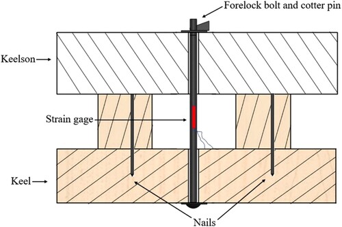
Table 1. Dimensions of experimental samples (Mathews & Steffy, Citation2004).
The wood species used by the shipwrights to construct the keelson and keel of the Serçe Limanı were Aleppo pine (Pinus halepensis) for the keelson and elm (Ulmus sp.) for the keel (Mathews & Steffy, Citation2004, p. 146). The validity of the FEA analyses and the subsequent laboratory tests were dependent on three factors: the similarity of mechanical properties of the chosen specimens representing the original Aleppo pine and elm structures, their availability, and the availability of their confirmed mechanical properties. Once these conditions are fulfilled, the properties such as mass density, tensile strength, the module of elasticity (MOE) and the yield strength, otherwise known as the module of rupture (MOR), were then inserted into the FEA software database.
Neither the original Aleppo pine nor elm were available. Hence, a meticulous sorting and selection process ensued to find close matches to the originals. The final choices were Oregon White oak (Quercus garryana) for the keel and Douglas fir (Pseudotsuga menziesii) for the keelson. Their comparative mechanical properties, MOR and MOE are shown in . The metallic components were manufactured from wrought iron, a low carbon iron similar to the 11th century iron used in the Serçe Limanı. The nails were 25 cm in length and 1 cm in diameter, a sectional dimension substituting the original 1 × 1 cm square section. The manufactured nail heads were bolts welded at one end, while the other end was ground to a sharpened point and driven through the frames and into the keel ().
Figure 14. Wrought iron nail manufactured for laboratory experimentation (photo: N. Helfman).
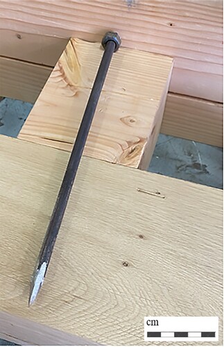
Table 2. Averaged mechanical properties of elm and oak species for bending and transverse stresses perpendicular (radial) to the grain (Ross, Citation2010).
The wrought iron bolt had a 2-cm-diameter shank (Mathews & Steffy, Citation2004, p. 116). A slot to receive the forelock wedge was incised at one end of the shank in a precision tooling shop. This was performed using electro-discharge machining (EDM), a machining process based on the erosion of metals by spark discharges (Sadegh & Worek, Citation2018, p. 513). The forelock wedge was manufactured in the same tooling shop by milling; a process which provided precision fit into the slot. In the absence of any standard engineering specifications, the production of the forelock bolt underwent a number of revisions in determining the optimal friction angle of the forelock.
Note in the red rectangle labelled ‘strain gauge’ in the generic illustration of the forelock bolt mounted between the keelson and the keel. The electrical resistance strain gauge consists of an electrical resistive wire, or foil, which is intimately attached to the specimen using a special purpose glue and gluing procedure. As the specimen is deformed, the gauge is deformed by the same amount, hence the resistance changes, thus rendering an exact and direct measurement of strain (Cloud, Citation2007, p. 265). The following describes the laboratory procedure by which the strain (ϵ) was measured in microstrain units, and ultimately compared to converted FEA simulation values of elongation displacement (δ):
In a section of the beams constructed to replicate the keelson-frames-keel assembly, a 2-cm-diameter hole was drilled directly through the keelson and keel, midway between two frame blocks.
The forelock bolt shank, fitted with a flat washer, was inserted into the pilot hole from the lower keel beam to protrude from the keelson beam above. It was securely held in place from below.
The protruding end of the bolt was fitted with a washer.
The forelock was then inserted as far as possible into the slot at the top of the bolt, without using force, so that it held the forelock bolt assembly in place by the initial friction.
From the edge of the forelock resting on the washer, a single line was incised on the washer indicating the ‘0’ starting point.
From the starting point, three more lines were incised 1 mm apart.
The strain gauge was then affixed, its wires connected to the monitoring apparatus which was then calibrated.
Three successive blows from a 1.5 kg sledgehammer impacted the outer edge of the forelock, each blow moving the forelock by 1 mm, and the values recorded.
The process was stopped after four blows when the upper washer began to sink into the wood, effectively influencing the strain measurement results.
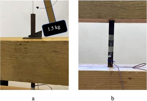
It was challenging to maintain consistent experimental conditions given the required 8 m/s velocity of the hammer blows. In order to achieve a close approximation of the required velocity, a simple pendulum was devised in which a hole was drilled at the end of a 1.5 kg sledgehammer with a handle 70 cm in length. The hole served as a pivot point of a make-shift pendulum which swung on a bolt situated directly above the forelock wedge. Calculations determined that in order to achieve the 8 m/s impact velocity, the hammer head had to be elevated 45.5 cm, or 65o from the perpendicular. After releasing, the hammer head impacted on the forelock wedge. Though rudimentary, the averaged results of each session demonstrated a high degree of repeatability of the strain values. illustrates the experimental set-up.
Figure 15. a) Replication of impact on the forelock of the bolt wedge protruding from the keelson; b) detail of the bolt fitted with a strain gage (photos: N. Helfman).
Results
The results are presented in and graphically in , comparing experimental laboratory results to the values calculated from the FEA simulations. The results increase at an almost identical rate of change (note the trendline in ). The values of both samples approach 3.9 × 10⁻³ ϵ, the value needed to achieve the required calculated preload at 4 mm insertion. These results verify and validate the FEA analysis of the forelock bolt. They have ramifications in a larger sense regarding the efficacy, utility, and the structural integrity of the Serçe Limanı ship.
Figure 16. Comparing strain results between FEA simulations and laboratory trials (Authors).
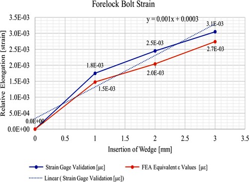
Table 3. FEA elongation (δ) and strain (ϵ) compared to validation strain values.
The efficacy of a bolt, whether threaded or forelocked, is determined by the preload generated. The theoretical value of the preload required to effectively join the keelson to the frames-keel assemblage was calculated at a preload of 53,000 N, an impact value of 16,000 N upon the forelock, with a theoretical elongation of 0.44 mm (Eqs. 1–11). This value, δ, was instrumental in developing the simulation and the subsequent laboratory validation.
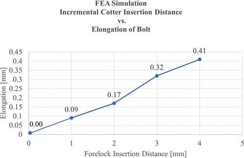
Given the δ, an FEA simulation was then devised in order to determine the insertion distance of the forelock resulting in an elongation of the bolt by that length. On each simulated incremental insertion, ten samples were taken and then averaged. The insertion of the forelock by 4 mm resulted a value of 0.41 mm elongation, closely matching the theoretical calculation. presents these results.
Figure 17. FEA simulation of the incremental insertion of the forelock versus elongation of the bolt (Authors).
Discussion
The viability of the keelson-frames-keel assemblage as integrated components of the hull structure of the Serçe Limanı ship was dependent on the extent to which it provided rigidity to the assemblage. The forelock bolt’s preload was the mechanical factor which ensured that the assemblage was an integrated rigid structure. This was demonstrated as feasible in the FEA simulations and laboratory validations: a single Serçe Limanı forelock bolt developed the required pre-calculated preload. These results (), demonstrate a close correspondence between the mathematical derivation and the experimental validation results. Jointed with a single bolt every five frames (Steffy, Citation2004), approximately ten bolts spanned the length of the keelson. These fully locked bolts acted as compressive springs in a series, each providing its proportional level of tension, more than enough to ensure adequate stiffness.
This configuration leaves the question of why the keelson was not simply nailed to the assemblage. The question was posed to an Israeli shipwright, who drawing from his own experience, proposed that the securely bolted keelson provided frame stability during manufacturing and the rapid disassembly which allowed an effective maintenance scheme for keel and frame repair or replacement. Nailed structures, he added, tended to be destructive during repair and maintenance procedures (N. Shamea, pers. comm., 2021). Moreover, although nailed structures generate friction between their fastened members, preload, as demonstrated in this study, can only be marginally generated. The forelock bolt is not subject to a nail’s loosening primarily due to ambient humidity, wood type and dynamic forces encountered during sailing. This precise methodology of bolting the keelson is echoed centuries later in Wooden Shipbuilding where the shipwright was explicitly instructed that the keelson is fastened in place with bolts that pass through floors and into the keel (Desmond, Citation1997, p. 55).
Based on the authors’ experience in preparing the validation testing, it can be attested that the meticulous preparation of a keelson-frames-keel-forelock bolt assembly is not trivial, even with modern technology. The wrought iron rods used in the laboratory validation were carefully tooled using electro-erosion, ensuring a precise forelock slot. The opposite end was threaded, allowing an adjustable length, and the forelock itself was manufactured on a milling machine. Although the production of a single bolt required many laborious hours, the most challenging process was drilling a precise pilot hole through 40 cm of Douglas fir and white oak beams. Any deviation of the hole from the perpendicular of both beams, or exact pilot hole diameter, significantly impaired the bolt’s capacity to generate the required tension, and hence, the compression in the beams securing the frames. How 11th century shipwrights achieved this feat without precision jigs, modern measuring devices, and heavy machinery, arouses the purest of adulation.
Conclusions
The results of the forelock bolt laboratory experiments and FEA simulations, based on the Serçe Limanı keelson-frames-keel assemblage, demonstrated that the forelock bolt achieved the preload required to join these components firmly in place. Its inclined plane compression system was equivalent to contemporary present-day threaded bolt systems. Efficient ship construction was facilitated by fixing the frames overlaid with a keelson and securely forelocked in place at the outset of the hull assembly. Moreover, the keelson, fixed in place with forelock bolts between the frames, ensured effective maintenance procedures on the keel and frames. Thus, the use of the forelock in the bolted keelson-frames-keel assemblage as represented in the Serçe Limanı ship demonstrated both effective structural engineering, and by virtue of efficient maintenance procedures, added economic value.
Conflicts of Interest
The authors declare no conflict of interest.
Author Contributions
Both authors conceptualised this research and defined this study’s objectives. Both authors discussed the results and contributed to the conclusions, wrote, read, and agreed to the published version of the manuscript.
Acknowledgements
This study was supported by a Sir Maurice Hatter Fellowship and the Dov Shafir Fellowship. The authors are grateful to E. Itzhack, Israel National Building Research Institute, for his valuable assistance, to J. B. Tresman for the English editing, and to the anonymous reviewers for their valuable comments and suggestions.
This article is dedicated to the memory of the late Professor Yaacov Kahanov, our teacher and friend.
References
- Barth, A., Caillaud, E. & Rose, B. (2011). How to validate research in engineering design? In DS 68-2: Proceedings of the 18th International Conference on Engineering Design (ICED 11), Impacting Society through Engineering Design, Vol. 2: Design Theory and Research Methodology (pp. 41–50). Technical University of Denmark.
- Cloud, G. L. (2007). Experimental stress and strain analysis. In A. M. Sadegh & W. M. Worek (Eds.), Marks’ standard handbook for mechanical engineers (pp. 265–267). McGraw-Hill Education.
- Desmond, C. (1997). Wooden ship-building. Vestal Press.
- Denkert, C., Kalkowsky, F. and Flügge, W. (2019). Experimental studies on the clamp length diameter ratio in highly stressed bolted joints. 24ème Congrès Français de Mécanique.
- DIN 25201-2 (2015 Design guide for railway vehicles and their components – Bolted connections – Part 2: Design – Mechanical engineering application, ICS Code (Bolts, screws, studs): 21.060.10 (pp. 1–36). Deutsches Institut für Normung e.V.
- Güntekin, E. & Aydin, T. V. (2013). Effects of moisture content on some mechancial properties of Turkish red pine (Pinus brutia). Artvin Çoruh University.
- Helfman, N. (2023). The Keelson: A marine architectural-archaeological analysis in the context of the transition in ship construction [Unpublished PhD dissertation]. University of Haifa, Haifa, Israel.
- Light, J. D. (2000). Observations concerning the hand forging of wrought iron. Materials Characterization, 45(4–5), 327–340.
- Mathews, S. D. & Steffy, J. R. (2004). The hull remains. In G. F. Bass (Ed.), Serçe Limanı eleventh-century shipwreck Vol. 1, The ship and its anchorage, crew, and passengers (pp. 81–123). Texas A&M University Press.
- McCarthy, M. (2005). Ships’ fastenings: From sewn boat to steamship. Texas A&M University Press.
- O'Sullivan, M. & Swailes, T. (2009). A study of historical test data for better informed assessment of wrought iron structures. International Journal of Architectural Heritage, 3(4), 260–275.
- Pomey, P., Kahanov, Y. & Rieth, E. (2012). Transition from shell to skeleton in ancient Mediterranean ship-construction: analysis, problems, and future research. International Journal of Nautical Archaeology, 41(2), 235–314.
- Ross, R. J. (2010). Wood handbook: Wood as an engineering material; general technical report FPL-GTR-113. United States Department of Agriculture.
- Sadegh, A.M. and Worek, W.M. (2018). Marks’ standard handbook for mechanical engineers. McGraw-Hill Education.
- Schlesinger, S. (1979). Terminology for model credibility. Simulation, 32(3), 103.
- Shigley, J. E., Mischke, C. R. & Budynas, R. G. (2004). Mechanical engineering design. First Metric Edition ed. McGraw-Hill.
- Steffy, J. (1994). Wooden ship building and the interpretation of shipwrecks. Texas A&M University Press.
- Steffy, J. R. (1982). The reconstruction of the 11th century Serçe Liman vessel A preliminary report. International Journal of Nautical Archaeology, 11(1), 13–34.
- Steffy, J. R. (2004). Construction and analysis of the vessel. Serçe Limanı: An eleventh-century shipwreck. In G. F. Bass, S. D. Matthews, J. R. Steffy & F. H. van Doorninck, Jr., Serçe Limanı: An eleventh-century shipwreck, Vol. 1, The ship and its anchorage, crew, and passengers (pp. 153–169). Texas A&M University Press.
- Yeomans, D. (2020). Repair of historic timber structures. ICE.
- Yu, Q. M., Yang, X. J. & Zhou, H. L. (2018). An experimental study on the relationship between torque and preload of threaded connections. Advances in Mechanical Engineering, 10(8), 1–10.