
 ?Mathematical formulae have been encoded as MathML and are displayed in this HTML version using MathJax in order to improve their display. Uncheck the box to turn MathJax off. This feature requires Javascript. Click on a formula to zoom.
ABSTRACT
The occurrence of multiple faults is a practical problem in the bearings of rotating machines, and early diagnosis of such issues in an intelligent manner is vital in the era of industry 4.0. The present work investigated various combinations of bearing faults, including dual and multiple fault conditions. Two prevalent fault diagnosis methods were employed: vibration monitoring using time-frequency scalograms extracted through Continuous Wavelet Transform (CWT) and a non-invasive Infrared Thermography (IRT). A 2-D Convolutional Neural Network (CNN) was used to classify various combinations of fault conditions through automated feature extraction. The proposed methodology was validated at two constant speed conditions of 19 Hz and 29 Hz and continuously accelerated and decelerated speed conditions in the range of 19 Hz - 29 Hz. Adequate accuracy was achieved in both dual and multiple fault conditions in the case of vibration-based fault diagnosis, with a range of 99.39 % to 99.97 %. Meanwhile, in the case of proposed IRT-based fault diagnosis, 100 % classification accuracy was achieved for dual and multiple faults in all conditions. These results signify the robustness and reliability of the proposed methodology for dual and multiple fault diagnosis in bearings at constant and varying speed conditions.
1. Introduction
Rotating machines are integrated part of every production and power generation system. Fault detection and isolation of rotating machine components are crucial as these faults could lead to a complete or partial shutdown of whole system. Also, these conditions could lead to accidents in the industries [Citation1–3]. Bearing is the most important component of these rotating machines, and correct and timely diagnosis of faults in the bearing is important for their safe operation [Citation4]. The faults can be found in any component of bearing, such as rolling element, inner race, outer race, or cage. However, the faults in actual industrial conditions occur in various combinations and may produce catastrophic conditions for rotating machines and may fail eventually. There are various sensors available for diagnosing these faults based on signals such as vibration, current, noise, temperature, etc. Among these, vibration is well established and older technique [Citation5,Citation6]. Researchers have used vibration monitoring assisted with various efficient methods such as Variational Mode Decomposition (VMD), and Maximum Correlation Kurtosis Deconvolution (MCKD) for the fault diagnosis of rolling element bearing [Citation7]. The advantages of the vibration monitoring are well defined, but still, it has various limitations such as contact with machine structure, frequent calibration, signal noise, damage to the sensor after long-term contact, etc. Apart from vibration-based fault diagnosis, another important method is infrared thermography which uses information based on temperature change and can be quickly and effectively used for fault diagnosis in rotating machine components in a non-invasive manner with strong immunity against the speed fluctuations [Citation8]. A thermal image is also known as a thermogram, which is simply a map of thermal energy. As an inherent characteristic, heat is radiated by each object, and its amount depends on the surface temperature [Citation9]. This phenomenon encourages the use of IRT as a prominent condition monitoring tool for faults in the components of rotating machines, such as bearing faults, misalignment [Citation10,Citation11] and faults in various electrical rotating machinery [Citation12–14].
In the practical working environment of rotating machines, the faults occur in various combinations. However, in the case of single fault conditions, commensurate modality sensors perform well, but in an actual working environment where faults occur in combination, a single modality sensor may be found less reliable. Also, in actual industrial scenarios, there are frequent fault conditions that, in combination with other kinds of faults, generate harsh conditions for a particular type of sensor capable enough to capture fault in normal conditions. One such situation is the lack of lubrication that leads to most of the faults in bearings and also causes a source of localised heat generation in the bearings. This limits the applicability of contact-type sensors such as vibration sensors and needs to be used in a complementary manner with other sensors having an effective non-contact information capturing capability regarding fault conditions [Citation15,Citation16]. So, in that complex environment where real-time decisions are to be made for effective and efficient maintenance of machines, the inspection with commensurate sensors is less reliable, and there is an urgent need for the involvement of different modality sensors [Citation17]. Further, researchers have done fault detection considering a single fault which is rarely the situation in practical working conditions, but less work is reported to diagnose multiple fault conditions in an unstable speed environment for bearings. These conditions demand extra effort as it is challenging to diagnose the characteristic frequencies and requires rigorous signal processing [Citation18].
There are various approaches available for fault diagnosis, including statistical methods, physics-based methods, and data-driven methods such as machine learning and deep learning. Statistical methods found their applications in fault diagnosis and other fundamental problems related to industrial and medical applications [Citation19–21]. These methods can be assisted with various efficient optimisation algorithms for accurate and efficient results [Citation22,Citation23]. The physics-based methods are based on the modelling of machine components and subsequent analysis in different fault conditions [Citation24]. However, in complex conditions, this method invites labour-intensive and time-consuming situations. In recent times, data-driven approaches such as machine learning and deep learning got much attention from the researchers and engineers, and advancement in computational power became a boon for these methods [Citation25,Citation26]. Machine learning-based methods got popular in recent decades and found effective solutions for fault diagnosis in rotating machines and other engineering problems [Citation27,Citation28]. However, methodologies based on machine learning involve mandatory feature extraction and hence require more effort. As opposed to this, deep learning became the front player due to its automated feature extraction capability, and growth in computational power makes it more prevalent among fault diagnosis researchers [Citation29]. The most widely used deep learning algorithms involve Convolutional Autoencoder (CAE), Deep Belief Network (DBN), Deep Boltzmann Machine (DBM), CNN, and Recurrent Neural Network (RNN) [Citation30,Citation31]. Among these techniques, CNN finds its place very strongly for the multi-sensor information and classification of faults as it has a lesser dependency on preprocessing [Citation32]. Multiple layers with activation functions leverage the CNN in extracting the complex features from data with single sensor data and multisensory data [Citation33]. A multi-sensor vibration-based classification was done using a Le-Net 5 CNN using the information from images converted by 1-D vibration signals for fault detection in a wind power test rig [Citation34]. In another work, various faults related to unbalance, rub, bearings, and feature extraction were done using CNN and Bag of Visual-Word (BoVW), aided by an algorithm called Scale-Invariant Feature Transform (SIFT). The faults were successfully classified with comprehensive accuracy using a Support Vector Machine (SVM) classifier [Citation35]. The usability of IRT-based methodology against vibration monitoring proved for the gear fault detection using CNN [Citation36].
In conclusion, a single or commensurate modality capturing sensor is limited by various conditions generated due to severe fault conditions in the components of rotating machines, and heat generation due to multiple faults is the most obvious and challenging one among these. So, there is a need to use non-invasive type sensors complemented with commercial contact type robust vibration transducers. This leads to a multilateral, reliable, and high-level fault recognition, ensuring timely, and effective decision-making regarding fault identification and classification.
In the present work, a vibration and infrared thermography-based approach is presented for a reliable and robust fault diagnosis in ball bearings based on deep learning. The important contributions of the present research are:
Various combinations of faults in ball bearing were experimentally analysed, including dual and multiple fault conditions at constant, accelerated, and decelerated speed conditions.
A 2-D CNN was designed to develop an automated feature extraction-based fault diagnosis of bearing faults in an intelligent manner and eliminate the efforts required for manual feature extraction.
Vibration monitoring through CWT-based time-frequency scalograms was used for the analysis and classification of various combinations of faults.
Further, a non-invasive infrared thermography was proposed that works on the heatmap or temperature distribution at the bearing surface. Moreover, the performance was comparatively analysed against vibration monitoring in single, dual, and multiple fault conditions.
The remaining part of the paper consists of the following sections. In Section 2, an explanation of experimentation and data acquisition is given. Section 3 describes the proposed deep learning-based fault diagnosis methodology. Section 4 elaborates the obtained results and the conclusions in Section 5.
2. Experimentation and data acquisition
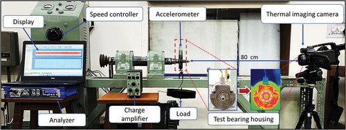
The experimentation was carried out on a robust bearing test rig having a DC motor of 220 V and 2 HP as a prime mover. The rig has strong support to facilitate various experimental simulation conditions like speed variation and different loading conditions, etc. shows the experimental setup used for the acquisition of vibration and thermography data. A uniaxial accelerometer (B&K, type 4370) with a sensitivity of 10 pC/ms−2 and a thermal imaging camera (FLIR-P640) having a frame rate of 7 with a resolution of 640 × 480 were used for the data acquisition. A sampling frequency of 6.4 kHz was utilised for acquiring the vibration data. For IRT, the most crucial parameter is emissivity, which depends on inspected material’s surface properties, and its typical value ranges from 0 to 1. In the present case, it is taken as 0.64 according to the bearing housing material [Citation37]. Another critical parameter is the apparent temperature that can be measured with standard methods; however, it has lesser significance for materials having higher emissivity. The distance between the camera and the target was 80 cm to focus on the bearing housing for accurate data collection.
Figure 1. Experimental setup for data acquisition.
Experiments were carried out at two constant speeds, i.e. 19 Hz and 29 Hz, and with continuously varying speeds as ramp up and ramp down of 10 Hz in five minutes, as given in . Also, the rig was run for 45 minutes before capturing the data for thermal stability and reaching steady-state conditions, as followed in [Citation38]. There was a rest of 60 minutes for the rig to reach room temperature for each fault condition.
Table 1. Dual and multiple fault conditions in bearing.
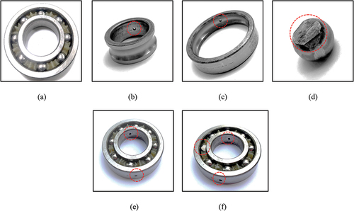
The combination of various fault conditions was experimentally simulated to analyse the dual and multiple fault conditions as given in . These faults include a combination of inner race fault (IR), outer race fault (OR), ball fault (BD), and lack of lubrication (LB). There are a total of five dual fault conditions that are considered. The combination of inner race fault and ball fault is depicted as ‘IRBD’; a combination of inner race fault and lack of lubrication is depicted as ‘IRLB’; a combination of inner race fault and outer race fault is depicted as ‘IROR’; a combination of the outer race and ball fault is depicted as ‘ORBD’, and a combination of outer race fault and lack of lubrication is depicted as ‘ORLB’ as given in . Similarly, a total of five multiple fault conditions were considered in the present work. Various fault conditions were combined to produce multiple fault conditions, where more than two faults can co-exist. As given in , ‘MF1’ - ‘MF4’ consist of three fault conditions, and ‘MF5’ consists of four fault conditions.
The different fault conditions are shown in , with one example of dual fault as ‘IROR’, and one example of multiple faults as ‘MF2’. For each experiment, except for the lack of lubrication condition, 100 % lubrication was done. Here 100% lubrication means 2.3 gm as recommended by the manufacturer, and lack of lubrication means 0 % lubrication. A grease SKF VKG 9/0.5IN was utilised for the lubrication of bearings.
Figure 2. Bearing conditions (a) healthy (b) inner race fault (c) outer race fault (d) ball fault (e) dual fault (f) multiple fault.
3. Proposed methodology
In this work, a deep learning-based strategy using CNN was adopted to diagnose ball bearing in various fault conditions. Here a 2-D CNN was designed, and image data was used for vibration and IRT. For the conversion of 1-D vibration data into images, the scalograms were obtained through CWT. Similarly, thermal images were extracted with proper RoI from the thermal video recorded by thermal camera.
3.1 Time-Frequency image extraction using CWT for vibration data
Traditional time domain and frequency domain analysis has the restriction on information from both the domain. Time-frequency-based analysis founds it application in effective way for the diagnosis of rotating machine components such as bearings [Citation39]. For time-frequency analysis, various techniques can be used, such as Short-Time Fourier Transform (STFT), CWT, Winger Ville distribution (WVD), and Pseudo-Winger Ville Distribution (PWBD) [Citation40,Citation41]. Using these techniques, 1-D data can be converted into 2-D images and further utilised for feature extraction. Such an example was presented in [Citation42], where a 1-D acoustic emission data was converted into a 2-D image and was utilised for classification using a CNN. A traditional Fast Fourier Transform (FFT) uses a basis function complex exponential form that includes sine and cosine but does not talk about occurrence time for the frequencies in the signal. The STFT uses windowing to analyse a section of the signal to catch the frequency content at a particular time but suffers from the curse of the uniqueness of good resolution either in the time or frequency domain. Against this, CWT provides better temporal and frequency resolution [Citation43].
The decomposition of signals through CWT is found effective as it decomposes signals into a series of superpositions of the mother wavelet by doing scaling and translation [Citation44]. Decomposition based on wavelet uses an oscillatory and time-localised function called mother wavelet that helps to cope with the issues associated with other decomposition methods [Citation45]. The source function is continuous in time as well as frequency domain. Mathematically CWT of a signal x(t) is given as:
Here is regarded as complex conjugate of the mother wavelet
, which is nothing but a continuous function in time as well as frequency domain, and
is translational factor or time shift, and b is scale factor. The
represents the original signal.
The purpose of scale factor is either dilation or compression of the original signal. The core target of the mother wavelet is basically to yield a source function to produce the daughter wavelets, which can be related to the mother wavelet as its translated and scaled versions. The choice of proper mother wavelet function depends on various factors such as variance in time and frequency domain and particular application. A ‘morlet’ wavelet is one of the widely used wavelets and is given as:
Here, can be regarded as centre of support found in Fourier space. In the present work, an analytic form of ‘morlet’ wavelet was used (popularly known as ‘amor’ wavelet) as a mother wavelet. It has a unique feature that provides equal variance in time and frequency. To convert 1-D vibration signal into a 2-D scalograms, the window-based conversion was adopted using the following equation:
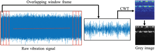
Where X is the total number of 2-D images extracted as time-frequency scalograms, N is the total number of data points, w is the window length, and c is the overlap factor which is taken as 50 % for the extraction of CWT coefficients. shows the extraction procedure for CWT-based scalograms. In the present case, the number of 2-D images was formed to tally the number in IRT to establish a fair comparison. So, here the calculated values of X are 2100, N is 1,920,000, and hence the round value of w was taken as 1826. The window-based strategy was adopted to eliminate information loss due to edging. The obtained scalograms contain information about both frequency and time at which a particular frequency is present in the signal.
Figure 3. Extraction of CWT-based scalogram based on overlapping window frames.
3.2 Image extraction for IRT data
As an inherent property, heat is radiated by each object, and its amount depends on the surface temperature and surface conditions. This phenomenon encourages the use of IRT as a prominent condition monitoring tool as faults in the components of rotating machines, such as bearings, etc. [Citation46]. The difference in temperature distribution in faulty conditions as compared to healthy conditions is an important source of information. Basically, infrared thermography makes it possible to visualise the superficial temperatures of a component in a non-invasive way with high resolution. This is achieved by measuring the radiation emitted by the component surface within the infrared region of the electromagnetic spectrum and by subsequently converting these radiations into electrical signals.
A black body is assumed to be the absorber of total incident radiation in the radiation process. Stefan-Boltzmann law is used to describe the emission rate per unit area as:
Here, Q is the total radiated energy per unit area, where ε is called emissivity, is called the Stefan-Boltzmann constant with an approximate value of 5.67 x 10⁻⁸ Wm−2 K−4, and T is the absolute temperature. Emissivity is a material property that is different for different materials and is important for accurate temperature measurement as well as capturing accurate thermal images [Citation47]. The value of emissivity for a perfectly black body is considered as 1. The factors associated with thermography are broadly mentioned in three categories as procedural, technical (material properties, distance, reflected temperature, specifications of camera etc.), and environmental (atmospheric temperature, humidity etc.). The heatmap generated using IRT can be used as an important source of information for diagnosing bearing faults. Thermal images are captured with the help of a thermal camera. This camera basically composed of the optical components (including lens, mirrors, etc.), detector elements, cooling arrangments, and related electronics. The present work extracted the thermal images of bearing from the complete frame by concentrating on RoI, as shown in . The raw thermal image can be seen as a temperature map generated through the FLIR tool. The pixel values of RGB thermal are represented in . It is clear from the map that the difference at pixel levels makes it a convenient tool for the diagnosis of different fault conditions.
Figure 4. Extraction of thermal images.
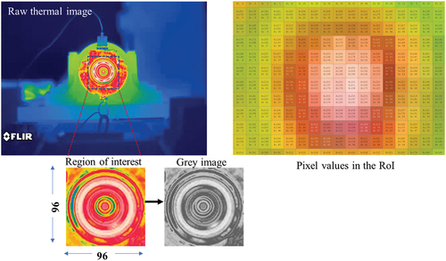
The setup was run for about 45 minutes before capturing the thermal data to attend the steady-state condition. However, the background of the whole image may be misled to the process, it is necessary to extract a RoI from the raw thermal images and convert it into greyscale imagess using the scale of [0, 255] and used as input to the CNN and classification of bearing fault conditions. The size of input images was fixed as 96 × 96 as per the input layer of CNN.
3.3 Convolutional neural network
In recent times, the convolutional neural network has been broadly acclaimed by the community of engineers and scientists. The primary reason for that is the capability of automatic feature extraction. In the basic structure of CNN, there are three main layers, i.e. the convolution layer, pooling layer, and fully connected layer [Citation48]. CNN gives a robust framework for learning and hierarchically extracting the features and working closely with the vital eyes [Citation49].
The input provided is in the form of 2-D images, which are further processed through various layers of the CNN structure. In the present case, the scalograms and thermal images are first converted into greyscale images as colour images lead to the curse of dimensionality without any substantial information addition. So, for the training and testing, greyscale images were used as they contain nearly the same information at pixel level as the colour image [Citation50]. This practice has a significant advantage as computational costs get significantly reduced. After getting the input as an image, a convolution operation is performed along with non-linear mapping and pooling, this can be regarded as a single task, and this task is repeated depending on the number of such layers. These layers in the form of a triplet are stacked on one another in a CNN architecture, and the number of these triplets determines the depth of a network. shows the proposed architecture of CNN for vibration and IRT-based fault diagnosis. A detailed description of the proposed CNN architecture is also given in . In the architecture of constructed CNN, a total of 16 layers are there, including three convolutional layers with batch normalisation and ReLu (Rectified Linear unit) layers. A batch normalisation layer was used as it contributes to faster training with reduced dependency on initial weights and a smooth regularisation of the model. Similarly, three max-pooling layers, one fully connected layer, and one output or classification layer were used with the SoftMax function. Convolution is given as the response of an imaging system, a linear space invariant system, to the input signal. This response is given as:
Figure 5. Proposed CNN for bearing fault diagnosis based on (a) vibration and (b) IRT.
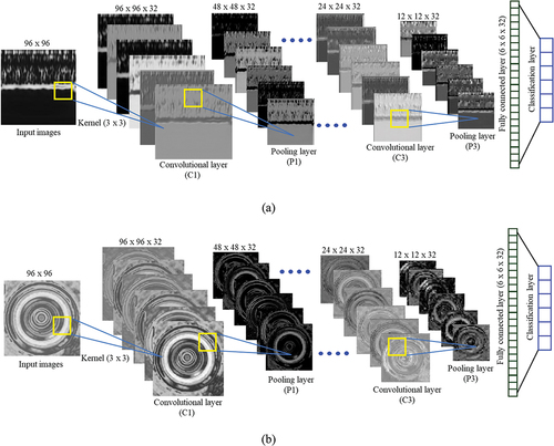
Table 2. Description of various layers in proposed CNN model.
Where h is regarded as the impulse response used to characterise the convolution process, m, n are the values of pixels in the input image, and a, b are pixel values in the resulting convoluted image. A finite convolution kernel extracts the particular feature by taking the particular portion of an image with a specified neighbourhood. Convolution operations involve many such convolutional kernels, which are nothing but a finite impulse response. The size of this kernel is specified by:
Where etc. So, now the values of m and n vary from -z to z. In the present case the kernel size was 3 by 3.
Sometimes padding is needed to get the size of the input and output image to be equal. Here, the ‘same’ padding was used to get the image as the input image size. The convolution kernel used in CNN is applied at every position of the input image, reducing parameters compared to conventional neural networks.
In flipping the kernel, each kernel coefficient is multiplied with corresponding pixel values of input images, and that gives the output response, and all such output responses for a particular kernel result in a convoluted image or feature map. When flipping the kernel on the input image, a particular region is to be flipped at a time, which is called the receptive field. The output of the convolution layer is passed through the ReLu layer, which makes the non-linear input feature map into a linearly separable feature by replacing all negative values in the feature map with zero. No specific parameters are required for this layer. Mathematically it can be taken as:
Here, x describes the input values. The output of this layer passed through the pooling layer. Window size and strides are essential parameters of the pooling layer. The present work applied max-pooling with a window of size 2 × 2 and stride was 2. The fully connected layer performs the classification task along with the classification layer. The classification layer has nodes equal to the number of classes or labels. The other important parameters for the training of CNN are optimiser, learning rate, number of epochs, validation frequency etc.
For this work, ‘sgdm’ optimiser was utilised to give a better result than other commonly used optimisers. The learning rate was 0.001, the validation frequency was 30, and the number of epochs was 100. From the total number of images for each dataset, 1575 images were used for training, and the remaining 525 images were used for testing purposes. The current designed model of CNN was tested for the MNIST digit dataset, which achieved a validation accuracy of 99.68 %. The training was done on a system having an ‘intel 4208’ CPU with a memory of 32 GB and NVIDIA-RTX2080, 11 GB single GPU in Matlab 2021b environment.
4. Results and discussion
The designed CNN model was trained with the same number of images for vibration and IRT data. Results are compared in terms of classification accuracies. The obtained confusion matrices from tested data in both cases were analysed with other important conclusions.
4.1 Vibration-Based fault diagnosis
Vibration monitoring is a well-established and most widely used method for fault diagnosis in rotating machines. The main advantage of using vibration-based analysis is that the signal analysis provides various characteristic frequencies for a particular fault condition. Traditional signal processing techniques can efficiently characterise a single fault condition. However, when the situation becomes complex, such as more than one fault with varying speed conditions, the method demands extra effort, and a simple signal processing method becomes less effective in such cases, and a series of signal processing may require. Wavelet analysis is such a method where the analysis can be done efficiently. Further, the artificial intelligence-based method allows automated and intelligent methods to identify faults with a pattern recognition-based methodology. In this case, the time domain data can be used as images using CWT containing time-frequency information, called scalograms, as explained in the previous section.
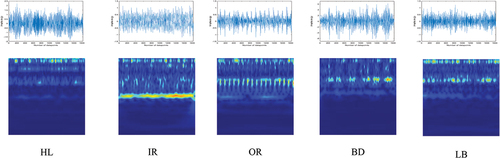
These obtained scalograms in colour form were first converted into grey images to prepare them for CNN input. The scalograms of single fault conditions at 19 Hz are shown in . It can be observed that some amount of modulation was observed with the highest in OR and BD. As explained earlier, the 75% data set from each level was taken as training data and 25% data for testing.
Figure 6. Raw vibration signals and scalograms of single fault conditions in bearing at 19 Hz.
shows the confusion matrices of different fault conditions at 19 Hz and 29 Hz for single fault conditions, which give the predicted and actual class values. The result for accuracy shows a perfect classification, i.e. 100 % accuracy at constant speed conditions, but slightly lower accuracy at ramp up, where there is a little confusion between the inner race and ball fault. However, at ramp down, the accuracy was 100 %. shows the raw vibration signature and respective scalograms at 19 Hz for dual fault conditions. A significant amount of modulation is observed in all dual fault conditions. gives the results for dual fault conditions. The classification rate is also near 100% for constant speeds with little confusion in ‘IRBD’ and ‘IROR’ classes for dual fault conditions. However, this confusion is more in the case of varying speed conditions, i.e. ramp up and ramp down. The result shows a promising trend of classification accuracy as most of the fault conditions were perfectly classified.
Figure 7. Raw vibration signals and scalograms of dual fault conditions in bearing at 19 Hz.
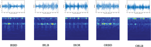
Table 3. Confusion matrices obtained through vibration-based monitoring for single faults.
Table 4. Confusion matrices obtained through vibration-based fault diagnosis for dual faults.
shows the raw vibration signature and respective scalograms at 19 Hz for multiple fault conditions. A much higher modulation is observed in all multiple fault conditions, with most in ‘MF2’ and ‘MF5’. The classification results obtained through the proposed CNN are given in for multiple faults. Here more confusion is observed among the classes than in the dual fault conditions. At constant speed, the confusion persists among ‘MF1’, ‘MF2’, and ‘MF5’. However, the confusion at varying speed conditions is among all the multiple fault conditions, with the maximum in the case of ‘MF2’ and ‘MF5’.
Figure 8. Raw vibration signals and scalograms of multiple fault conditions in bearing at 19 Hz.
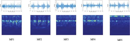
Table 5. Confusion matrices obtained through vibration-based fault diagnosis for multiple faults.
4.2 Infrared thermography-based fault diagnosis
Although vibration monitoring is considered a prominent and well-established technique and is also proven here, but is associated with some inherent issues, the common issue involved with vibration-based monitoring are physical mounting and sensor damage for long-time contact. Also, finding out the characteristic frequencies to determine the actual fault type when the component gets hampered by multiple faults becomes challenging, as discussed in the previous section. Being a non-invasive method, IRT has an advantage in those situations for fault diagnosis. The temperature distribution pattern in various fault conditions makes it possible to detect them on a trained system accurately. However, at the laboratory level, it is recommended to run the setup for a specified time to achieve the steady-state conditions for any clear discrimination between the said fault conditions. However, this limitation is accessible in the actual industrial environment, where the machines work for longer hours.
The thermal images of all conditions at 19 Hz are shown in for single faults. An important observation from these images is a significant heat transfer from the bearing to the adjacent housing part, especially in case of lack of lubrication. Also, from , a more uniform heat distribution is observed in case of lack of lubrication as against the other conditions that indicate a higher heat generation, and that condition can be easily detected with IRT-based monitoring. In addition, the main problem arises when other geometrical faults aid the lack of lubrication in the bearing. Such conditions make it very difficult for an accelerometer to capture the data accurately and smoothly. IRT, in such cases, finds its place by doing a perfect job for pattern recognition by generating the data in thermal images. gives the classification results for the single faults using IRT. All the fault conditions were classified with 100% accuracy at all speed conditions. The thermal images of different dual fault conditions at 19 Hz are shown in . A slight difference was observed in the heat distribution in RoI for the different dual fault conditions. However, with naked eyes, the task of discrimination is problematic and should be made automated for intelligent fault diagnosis.
Figure 9. Thermal images of different single fault conditions in bearing at 19 Hz.
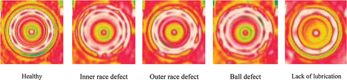
Figure 10. Thermal images of different dual fault conditions in bearing at 19 Hz.
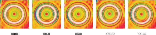
Table 6. Confusion matrices obtained through IRT-based fault diagnosis for single faults.
The classification results of different dual fault conditions are given in . It was observed that the classification accuracies for each class are 100%, with no confusion among the classes. The pattern of perfect classification persists for constant speed conditions as well as varying speed conditions, i.e. ramp up and ramp down.
Table 7. Confusion matrices obtained through IRT-based fault diagnosis for dual faults.
The thermal images of different multiple fault conditions at 19 Hz are shown in . The most friction-contributing fault is the ball fault, and this fault is included in all multiple faults, excluding ‘MF1’. The heat distribution pattern seems more uniform in ‘MF3’, ‘MF4’, and ‘MF5’. The classification results for multiple fault conditions are given in . It can be observed from the results that the capability of IRT to discriminate the different fault conditions as the classification results are perfect for all the fault conditions at constant and varying speed conditions.
Figure 11. Thermal images of different multiple fault conditions in bearing at 19 Hz.
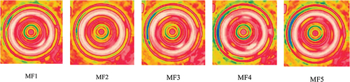
Table 8. Confusion matrices obtained through IRT-based fault diagnosis for multiple faults.
Figure 12. Validation accuracy of vibration and IRT-based fault diagnosis (a) single faults (b) dual faults (c) multiple faults.
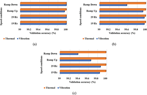
The comparison of validation accuracies for vibration and IRT is shown in . It can be observed that with the use of CWT-based time-frequency scalograms, the classification task becomes much more efficient. In the case of single fault conditions, the accuracy is 100 %, except for the ramp-up condition. The results show the classification accuracy is quite adequate in dual fault conditions with a maximum value of 99.97 % at 19 Hz and 29 Hz and a minimum at ramp-down conditions with 99.59 %. Similarly, the maximum accuracy for vibration monitoring for multiple fault conditions is 99.88 % at 29 Hz, and the minimum is 99.39 % at the ramp-down condition.
The reason for 100 % classification in all the conditions using thermography may be due to the advantage of thermal profile change in different conditions. Although the results give 100 % classification accuracy in all the conditions of single, dual, and multiple faults in the IRT-based classification, it also has an inherent issue against vibration monitoring. It is difficult to generalise the results for any rotating machines, as in the case of vibration monitoring, the characteristic frequency relates to the geometrical parameters of bearing. However, the advantage of thermal-based monitoring can be taken for specific types of rotating machines and generalised for similar kinds of machines that the industries usually contain. However, the thermographic analysis for rotating machines is developing, and researchers are working on empirical relations with the geometrical measures of rotating machine components.
The presented proposed methodology based on CNN was also compared with the recent research work as given in . As mentioned earlier, very little work is reported on multiple faults at individual component levels such as bearing. However, few researchers have studied system-level multiple faults in the rotating machines. Shao et al [Citation51]. used IRT for the diagnosis of various dual fault conditions in a rotor-bearing system. The system was tested using CAE and an enhanced CNN at two-speed conditions. Similarly, in work done by Xin et al [Citation52], various faults were studied using IRT data at continuously increasing speed. The classification task was achieved through a Gaussian deep belief network, and an accuracy of 99.24 % was achieved. A deep CNN and SVM were used for dual faults in bearing by Xue et al. at a constant speed of 1465 rpm and achieved an accuracy of 98.71 % [Citation53].
Table 9. Comparison of the proposed work with previous research work on bearing fault diagnosis.
Sparse Representation Classifier (SRC), in combination with wavelet kernel-based extreme learning machine, was used for the classification of three single and one multiple fault conditions in bearing with an accuracy of 95.67 % [Citation54]. Acoustic emission was explored for the diagnosis of various dual and multiple fault conditions using SVM with validation at different constant speed conditions, and different data sets and 100 % accuracy were formulated in six data sets out of 10 datasets [Citation55]. Various single fault conditions were also studied in our previous using SVM with data from individual modalities i.e. vibration and IRT, and with their fusion and an accuracy of 100 % was achieved [Citation56]. However, with SVM, mandatory manual feature extraction is associated. Similarly, single and dual faults were studied using CNN assisted with Particle Smarm Optimised – Support Vector Machine (PSO-SVM) and feature level fusion by converting the 1-dimensional vibration data into images [Citation57]. In the proposed work, single, dual and multiple fault conditions were studied using a CNN with vibration and IRT. The validation was presented at constant as well as varying speed conditions. The results for time-frequency-based diagnosis were quite adequate in dual as well as multiple fault conditions. Meanwhile, the proposed IRT-based fault diagnosis provides classification results as 100 % at a constant as well as varying speeds.
5. Conclusions
In a rotating machine, components such as bearing, and various faults can co-exist in combination. A commensurate modality sensor has limitations for the accurate and reliable diagnosis of bearing faults. In the proposed work, a vibration monitoring method and non-invasive infrared thermography were presented, and the results are validated for a different combination of faults at constant and varying speeds. A CNN network was utilised for the automated fault diagnosis using the extracted vibration and thermal images. The time-domain information lags the complete information about the frequency content at a particular time, which may hinder the correct diagnosis of the fault. So, a time-frequency scalogram using CWT is utilised as the input to the CNN. Similarly, a non-invasive IRT was employed, and thermal images were extracted with a proper RoI. Adequate results were obtained using CWT-based time-frequency scalograms with maximum accuracy in the case of dual faults as 99.97 % at a constant speed and 99.94 % at varying speeds, respectively. These values for multiple faults were 99.88 % and 99.67 %, respectively.
Further, 100 % classification accuracy was achieved in the proposed IRT-based fault diagnosis for constant as well as varying speed conditions. These results demonstrate the reliability and robustness of the proposed method for bearing fault diagnosis. Also, the results demonstrate that the IRT-based diagnosis was more effective in fault detection and coping with other issues inherited with vibration monitoring. However, the thermal-based analysis may be limited by the cost aspect, but the one-time investment could be helpful for quick and effective decision-making regarding the effective and reliable multiple fault diagnosis of bearing. Future work will involve the fusion of vibration and IRT through experimental simulation of the multiple fault conditions by incorporating more complex working conditions.
Acknowledgments
The authors are thankful to the ‘Ministry of Education, Government of India, for the support in conducting this work.
Disclosure statement
No potential conflict of interest was reported by the author(s).
References
- Choudhary A, Goyal D, Shimi SL, et al. Condition monitoring and fault diagnosis of induction motors: a review. Arch Comput Methods Eng. 2019;26(4):1221–1238. DOI:10.1007/s11831-018-9286-z
- Goyal D, Choudhary A, Pabla BS, et al. Support vector machines based non-contact fault diagnosis system for bearings. J Intell Manuf. 2020;31:1275–1289.
- Zhao H, Yang X, Chen B, et al. Bearing fault diagnosis using transfer learning and optimized deep belief network. Meas Sci Technol. 2022;33:065009.
- Deng W, Li Z, Li X, et al. Compound fault diagnosis using optimized MCKD and sparse representation for rolling bearings. IEEE Trans Instrum Meas. 2022;71:1–9.
- Mishra RK, Choudhary A, Fatima S, et al. An intelligent bearing fault diagnosis based on hybrid signal processing and Henry gas solubility optimization. Proc Inst Mech Eng Part C J Mech Eng Sci. 2022:095440622211017. DOI:10.1177/09544062221101737
- Cui H, Guan Y, Deng W. Fault diagnosis using cascaded adaptive second-order tristable stochastic resonance and empirical mode decomposition. Appl Sci. 2021;11(23):11480.
- Cui H, Guan Y, Chen H. Rolling element fault diagnosis based on VMD and sensitivity MCKD. IEEE Access. 2021;9:120297–120308.
- Younus AM, Widodo A, Yang BS. Evaluation of thermography image data for machine fault diagnosis. Nondestruct Test Eval. 2010;25:231–247.
- Mehta A, Choudhary A, Goyal D, et al. Infrared thermography based fault diagnosis and prognosis for rotating machines. J Univ Shanghai Sci Technol. 2021;23:22–29.
- Yuan Z, Zhang L, Duan L. A novel fusion diagnosis method for rotor system fault based on deep learning and multi-sourced heterogeneous monitoring data. Meas Sci Technol. 2018;29(11):115005.
- Fatima S, Mohanty AR, Naikan VNA. A misalignment detection methodology by measuring rate of temperature rise of shaft coupling using thermal imaging. Proc Inst Mech Eng Part O J Risk Reliab. 2015;229:209–219.
- Choudhary A, Mian T, Fatima S, et al. Passive thermography based bearing fault diagnosis using transfer learning with varying working conditions. IEEE Sens J. 2022. DOI:10.1109/JSEN.2022.3164430.
- Glowacz A, Glowacz Z. Diagnosis of the three-phase induction motor using thermal imaging. Infrared Phys Technol. 2017;81:7–16.
- Choudhary A, Goyal D, Letha SS. Infrared thermography-based fault diagnosis of induction motor bearings using machine learning. IEEE Sens J. 2021;21:1727–1734.
- Mian T, Choudhary A, Fatima S Multi-Sensor fault diagnosis for misalignment and unbalance detection using machine learning. In: Proc International conference on power electronics, smart grid and renewable energy (PESGRE 2022); Trivandrum, Kerala, India; 2022;1–6.
- Li C, Sanchez RV, Zurita G, et al. Gearbox fault diagnosis based on deep random forest fusion of acoustic and vibratory signals. Mech Syst Signal Process. 2016;76–77:283–293.
- Huang M, Liu Z, Tao Y. Mechanical fault diagnosis and prediction in IoT based on multi-source sensing data fusion. Simul Model Pract Theory. 2020;102:101981.
- Nguyen PH, Kim JM. Multifault diagnosis of rolling element bearings using a wavelet kurtogram and vector median-based feature analysis. Shock Vib. 2015;2015:1–14.
- Li G, Li Y, Chen H, et al. Fractional-Order controller for course-keeping of underactuated surface vessels based on frequency domain specification and improved particle swarm optimization algorithm. Appl Sci. 2022;12:3139.
- Minhas AS, Singh S. A new bearing fault diagnosis approach combining sensitive statistical features with improved multiscale permutation entropy method. Knowledge-Based Syst. 2021;218:106883.
- Zhang X, Wang H, Du C, et al. Custom-Molded offloading footwear effectively prevents recurrence and amputation, and lowers mortality rates in high-risk diabetic foot patients: a multicenter, prospective observational study. Diabetes, Metab Syndr Obes Targets Ther. 2022;15:103–109.
- Zhou X, Ma H, Gu J, et al. Parameter adaptation-based ant colony optimization with dynamic hybrid mechanism. Eng Appl Artif Intell. 2022;114:105139.
- Deng W, Zhang X, Zhou Y, et al. An enhanced fast non-dominated solution sorting genetic algorithm for multi-objective problems. Inf Sci. 2022;585:441–453.
- Wang P, Xu H, Yang Y, et al. Dynamic characteristics of ball bearing-coupling-rotor system with angular misalignment fault. Nonlinear Dyn. 2022;108:3391–3415. DOI:10.1007/s11071-022-07451-1.
- Liu R, Yang B, Zio E, et al. Artificial intelligence for fault diagnosis of rotating machinery: a review. Mech Syst Signal Process. 2018;108:33–47.
- Zheng J, Yuan Y, Zhao H, et al. A novel broad learning model-based semi-supervised image classification method. IEEE Access. 2020;8:116756–116765.
- Mian T, Choudhary A, Fatima S. An efficient diagnosis approach for bearing faults using sound quality metrics. Appl Acoust. 2022;195:108839.
- Chen H, Miao F, Chen Y, et al. A Hyperspectral image classification method using multifeature vectors and optimized KELM. IEEE J Sel Top Appl Earth Obs Remote Sens. 2021;14:2781–2795.
- Yin L, Hong P, Zheng G, et al. A novel image recognition method based on DenseNet and DPRN. Appl Sci. 2022;12(9): 1–14. DOI:10.3390/app12094232.
- Zhao R, Yan R, Chen Z, et al. Deep learning and its applications to machine health monitoring. Mech Syst Signal Process. 2019;115:213–237.
- Deng W, Liu H, Xu J, et al. An improved quantum-inspired differential evolution algorithm for deep belief network. IEEE Trans Instrum Meas. 2020;69:7319–7327.
- Huang K, Wu S, Li F, et al. Fault diagnosis of hydraulic systems based on deep learning model with multirate data samples. IEEE Trans Neural Networks Learn Syst. 2021;1–13. DOI:10.1109/TNNLS.2021.3083401.
- Kumar P, Hati AS. Deep convolutional neural network based on adaptive gradient optimizer for fault detection in SCIM. ISA Trans. 2021;111:350–359.
- Wang H, Li S, Song L, et al. An enhanced intelligent diagnosis method based on multi-sensor image fusion via improved deep learning network. IEEE Trans Instrum Meas. 2020;69:2648–2657.
- Jia Z, Liu Z, Vong CM, et al. A rotating machinery fault diagnosis method based on feature learning of thermal images. IEEE Access. 2019;7:12348–12359.
- Li Y, Xi Gu J, Zhen D, et al. An evaluation of gearbox condition monitoring using infrared thermal images applied with convolutional neural networks. Sensors (Switzerland). 2019;19(9):2205. DOI:10.3390/s19092205
- Oliveira BCF, Seibert AA, Borges VK, et al. Employing a U-net convolutional neural network for segmenting impact damages in optical lock-in thermography images of CFRP plates. Nondestruct Test Eval. 2021;36:440–458.
- Choudhary A, Mian T, Fatima S. Convolutional neural network based bearing fault diagnosis of rotating machine using thermal images. Meas J Int Meas Confed. 2021;176:109196.
- Li X, Zhao H, Yu L, et al. Feature extraction using parameterized multi-synchrosqueezing transform. IEEE Sens J. 2022;22(14): 14263– 14272. DOI:10.1109/JSEN.2022.3179165.
- Mishra RK, Choudhary A, Mohanty AR, et al. Multi-Domain bearing fault diagnosis using support vector machine. IEEE 4th Int Conf Comput Power Commun Technol (GUCON 2021), Kuala Lumpur, Malaysia. 2021;1–6.
- Yan J, Laflamme S, Singh P, et al. A comparison of time-frequency methods for real-time application to high-rate dynamic systems. Vibration. 2020;3:204–216.
- Hasan MJ, Islam MMM, Kim JM. Multi-Sensor fusion-based time-frequency imaging and transfer learning for spherical tank crack diagnosis under variable pressure conditions. Meas J Int Meas Confed. 2021;168:108478.
- Jadhav P, Rajguru G, Datta D, et al. Automatic sleep stage classification using time–frequency images of CWT and transfer learning using convolution neural network. Biocybern Biomed Eng. 2020;40:494–504.
- Zhao H, Liu J, Chen H, et al. Intelligent diagnosis using continuous wavelet transform and gauss convolutional deep belief network. IEEE Trans Reliab. 2022;1–11. DOI:10.1109/TR.2022.3180273.
- Han T, Chao Z. Fault diagnosis of rolling bearing with uneven data distribution based on continuous wavelet transform and deep convolution generated adversarial network. J Brazilian Soc Mech Sci Eng. 2021;43:1–16.
- Derusova DA, Vavilov VP, Shpilnoi V, et al. Characterising hidden defects in GFRP/CFRP composites by using laser vibrometry and active IR thermography. Nondestruct Test Eval. 2022;00:1–19.
- Lopez-Perez D, Antonino-Daviu J. Application of infrared thermography to failure detection in industrial induction motors: case stories. IEEE Trans Ind Appl. 2017;53:1901–1908.
- Wang S, Xiang J, Zhong Y, et al. Convolutional neural network-based hidden Markov models for rolling element bearing fault identification. Knowledge-Based Syst. 2018;144:65–76.
- Li Y, Du X, Wan F, et al. Rotating machinery fault diagnosis based on convolutional neural network and infrared thermal imaging. Chin J Aeronaut. 2020;33:427–438.
- Cocoma-Ortega JA, Martinez-Carranza J. A compact CNN approach for drone localisation in autonomous drone racing. J Real-Time Image Process. 2022;19:73–86.
- Shao H, Li W, Xia M, et al. Fault diagnosis of a rotor-bearing system under variable rotating speeds using two-stage parameter transfer and infrared thermal images. IEEE Trans Instrum Meas. 2021;70. DOI:10.1109/TIM.2021.3111977.
- Xin L, Haidong S, Hongkai J, et al. Modified Gaussian convolutional deep belief network and infrared thermal imaging for intelligent fault diagnosis of rotor-bearing system under time-varying speeds. Struct Heal Monit. 2022;21:339–353.
- Xue Y, Dou D, Yang J. Multi-Fault diagnosis of rotating machinery based on deep convolution neural network and support vector machine. Meas J Int Meas Confed. 2020;156:107571.
- Zhang S, He X, Liu Z. Cooperative classification method for multi-fault diagnosis of machinery based on parameterized wavelet kernel extreme learning and sparse representation. Meas Sci Technol. 2021;32:115903.
- Manjurul Islam MM, Kim JM. Reliable multiple combined fault diagnosis of bearings using heterogeneous feature models and multiclass support vector Machines. Reliab Eng Syst Saf. 2019;184:55–66.
- Mian T, Choudhary A, Fatima S. A sensor fusion based approach for bearing fault diagnosis of rotating machine. Proc Inst Mech Eng Part O J Risk Reliab. 2021;236(5):661–675. DOI:10.1177/1748006X211044843.
- Xue F, Zhang W, Xue F, et al. A novel intelligent fault diagnosis method of rolling bearing based on two-stream feature fusion convolutional neural network. Meas J Int Meas Confed. 2021;176:109226.