Abstract
In the present work a combination of the absorption and scattering coefficients in heterogeneous two-dimensional media is estimated using the source–detector methodology and a discrete ordinates method whose directions of radiation propagation are taken in a way that is consistent with the source–detector system for parallel beams of radiation.
The domain partition, the solution of the direct problem, and the source–detector methodology are described. Test case results are also presented.
1. Introduction
The well-known transmission tomography is based on a simplification of the linearized Boltzmann equation in which the scattering phenomenon is not taken into account [Citation1–Citation3], but in some practical applications scattering cannot be neglected [Citation4–Citation6]. In such cases the mathematical modelling for the radiation propagation within the medium may be made using an approximation for the transport equation based on the discretization of the angular domain in the so called discrete ordinates, being therefore reduced to a set of first order ordinary differential equations [Citation7].
In the present work the domain partition is constructed to be consistent with the directions of propagation of the parallel beams of radiation. These directions are therefore used for the discrete ordinates scheme, allowing the solution of the direct problem with a discontinuous Galerkin method marching along each of the discrete ordinates directions. The formulation of the inverse problem with the source–detector methodology [Citation4,Citation5,Citation8–Citation10] leads to a system of non-linear integral equations. The solution of the inverse problem is done with q-ART type algorithms [Citation1], based on the method of projection into convex sets.
2. Mathematical Formulation of the Direct Problem
Consider an absorbing and scattering two-dimensional medium with no internal radiation sources, subjected to externally generated parallel beams of radiation.
For the steady-state situation, with no spectral dependency, the following mathematical formulation is obtained from the linearized Boltzmann equation [Citation11,Citation12] which is used for the modelling of the interaction of the radiation with the participating medium
(--1-)
where φ is the radiation intensity,
is a given location in the domain,
is the direction of radiation propagation, σt is the total extinction coefficient (absorption + out scattering), σs is the scattering coefficient, and
is the direction of incident radiation that is scattered at point
into the direction
.
In order to complete the mathematical formulation of the direct problem of radiative transfer represented by Eq. (Equation1a(--1-) ) boundary conditions are necessary. Considering that the intensity of the externally incident radiation source is known,
, we write
(--1-)
where
is the boundary of domain D through which the external radiation comes into the medium, and
is the outward normal at point
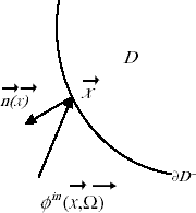
of the boundary, as schematically represented in .
Observe that no internal sources are taken into account in our analysis, and the boundaries of the medium are transparent, i.e. no reflections at the boundaries are considered.
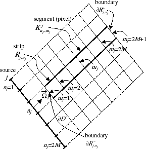
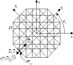
Using a pixel mesh consistent with parallel beams of radiation, as shown in and considering a particular direction with a coordinate system given by (sj, tj) that is rotated in accordance with the particular direction
, as shown in , Eq. (Equation1a
(--1-) ) can be written for each strip
in the following way
FIGURE 3 Domain partition consistent with parallel beams of radiation, and corresponding rotated coordinate system.
The boundary condition (Equation1b(--1-) ) is then written as
(--2-)
where
represents the boundary of the strip
through which the external radiation comes into the strip.
2.1. Rotated Discrete Ordinates Approximation
Adopting the coordinate system that rotates in accordance with each particular direction , the first term in the left hand side of Eq. (Equation2a
(--2-) ) can be written as
(--3)
The formulation of the radiative transfer problem given by Eq. (Equation2
(--2-) ) consists of a discrete ordinates formulation [Citation13] with the discretization of the angular domain being made in a way that is consistent with parallel beams of radiation originated at external sources.
Given the geometry, the radiative properties, and the boundary conditions, the values of φj, j = 1,2, … ,2J, at each segment (pixel) , comprised between mj and mj + 1, with mj = 1,2, … ,2M, for each strip
, with nj = 1,2, … ,2M, can be calculated. This is the direct problem. For each strip
there is an ordinary differential equation to be solved. Therefore, there is a system of 4JM coupled equations to be solved. In fact, due to the symmetry of the problem there are only 2JM independent equations.
Rearranging the summation terms on the right hand side of Eq. (Equation2a(--2-) ), and using Eq. (Equation3
(--3) ) to replace the first term on the left hand side of Eq. (Equation2a
(--2-) ), we obtain the following matricial form
(--4-)
or
(--4-)
where the elements of matrix C,
, l = 1,2, … , 2J and m = 1,2, … , 2J, are given by the following combination of scattering and absorption coefficients
(--5-)
(--5-)
and also
(--6-)
(--6-)
The formulation given by Eq. (Equation4(--4-) ) is similar to that employed in computerized transmission tomography, but here the detectors are influenced not only by the transmitted but also by the scattered radiation.
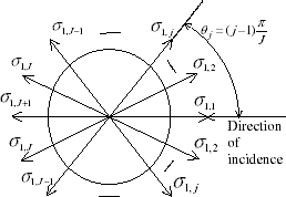
Considering the rotational symmetry of the source–detector system adopted in the present work, matrix C is symmetrical and cyclical, being written in the form
(--7)
One can observe that every row of matrix C is obtained from the previous one by just making a shift of the coefficients to the right.
represents the first row of matrix C, taking into account the symmetry of the scattering coefficients with respect to the incident direction.
Shifting the direction of incidence by an angle
Eqs. (Equation6a(--6-) ) and (Equation6b
(--6-) ) are confirmed.
For the solution of the direct problem given by Eqs. (Equation4(--4-) )–(Equation7
(--7) ) we now march along the discrete directions
, j = 1, 2… , 2J, following each one of the strips
, with nj = 1,2,…,2M. For each direction
the corresponding coordinate system (sj,tj) is used.
To the best of our knowledge this is a new procedure in the context of the discrete ordinates method, i.e. the use of the domain partition consistent with the source–detector system [Citation14] to derive the directions to be used in the discretization of the angular domain [Citation13].
2.2. Domain Partition
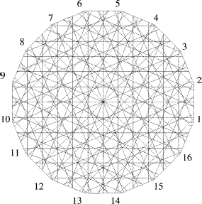
There is a total of 2J regular square meshes, here called pixel meshes (see ), each one of them compatible with one angular direction for radiation propagation . In each of these rotated coordinate systems (see ) the transport problem can be written as a one-dimensional problem. The complete intersection of all pixel meshes is taken into account, generating the domain partition in polygons pe with e = 1,2, … , E, where E is the total number of polygons. In we present one domain partition considering 2J = 16 directions, with 2M = 12 strips for each direction.
First, the intersections of all lines are calculated (observe that each strip has two limiting lines). The points where the intersections take place are the vertices of the polygons pe. Then a major task has to be performed; that is, from a set of vertices (x1, y1), (x2, y2), … , (xL, yL) where L is the total number of intersection points, we have to identify those that form a polygon. An algorithm has been developed, in which for each rectangular pixel, we sequentially investigate, for all intersection points contained in the interior or at the boundary of the pixel, all possible elements that can be created around each intersection point. Obviously each intersection point has to be a vertex of all polygons created around it. The polygons constructed in this way are characterized by the indices that relate the intersection points with the indices of all strips (and respective sources) that gave origin to them. Afterwards, in the polygons numbering step, if a polygon is created identical to the polygon created by another of its vertices, the element counter is not increased by one. In this way multiplicity is avoided in the process of polygons numbering, and at the same time the vertices that belong to each polygon are determined.
The output of the computer code written for the construction of the natural base of simple Lebesgue functions consists on the ordered listing of all polygons, their areas, optionally their vertices, and its pertinence matrix (or incidence matrix) for its localization in each one of the oriented pixels. The pertinence matrix is defined by two sets of indices, i.e. and
that locates each particular element e with respect to the rotated coordinate system (sj, tj), j = 1,2, … ,2J.
A computer code for the automatic mesh generation was written in the MATLAB® environment. More information about this kind of mesh generation can be found in the works by Reis and Roberty [Citation14] and Carita et al. [Citation1–Citation3]. The set characterization of the oriented pixels represented in , is given by
(--9-)
and
is the domain partition composed by the polygons e = 1, … ,E, i.e.
(--9-)
where ae is the area of polygon pe.
3. Solution of The Direct Problem
Both the solution of the direct problem and the formulation of the source–detector methodology to be used in the inverse problem solution [Citation4,Citation5,Citation8–Citation10], were performed in the context of the Galerkin discontinuous finite element method formulated by Lesaint and Raviart [Citation15,Citation16]. The combination of the discontinuous finite element formulation with a domain partition constructed consistently with the discrete ordinates oriented pixel meshes produces a simplified and robust algorithm for solving the discrete problem, as well as to formulate the respective reconstruction inverse problem.
The system of equations (Equation4(--4-) ) and the proper boundary conditions may be written as
(--10-)
(--10-)
for j = 1,2, … ,2J and nj = 1,2, … , 2M.
We have adopted the following representation for the radiation intensities
(--11-)
where
(--11-)
and
where Pr is the set of polynomials of degree r≥0.
For the combination of absorption and scattering coefficients we have used
(--12)
where the characteristic function χe assumes the following values
The approximation space for this discontinuous radiation intensity representation is [Citation17]
(--14)
The variational formulation for Eq. (Equation2a
(--2-) ) is given by [Citation16]
(--15)
where
represents the influx boundary of the pixel
is the jump at the influx boundary, and g corresponds to the term on the right hand side of Eq. (Equation2a
(--2-) ). If we adopt a constant polynomial inside the rotated pixel, i.e. r = 0 and therefore p(sj) = constant, we obtain from Eq. (Equation15
(--15) ), taking into account Eqs. (Equation4
(--4-) )–(Equation7
(--7) ) and (Equation10
(--10-) ), the following discretized equation
(--16-)
where
(--16-)
(--16-)
(--16-)
and
is obtained at the segment (pixel)
such that
, and may be represented by
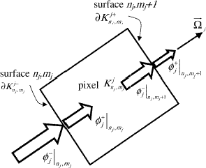
In are represented the pixel and the radiation intensities at the influx and outflux boundaries,
and
, respectively.
FIGURE 6 Rotated pixel Knj, mjj and representation of radiation intensities for the discontinuous Galerkin finite element method.
When for all j, nj and mj, Eq. (Equation10
(--10-) ) can be rewritten as
A discretized version of Eq. (Equation17a(--17-) ) can be derived in a similar way to that used to obtain Eq. (Equation16a
(--16-) ) from Eq. (Equation10a
(--10-) ).
Using either Eq. (Equation16(--16-) ) or Eq. (Equation17
(--17-) ) the solution of the direct problem of radiative transfer is obtained simply by marching along the directions
, for each strip
, with j = 1,2,…,2J, nj = 1,2,…,2M, and mj = 1,2,…,2M, starting at
where the boundary conditions are known.
This procedure is repeated until convergence on the calculated values for the radiation intensities is observed.
4. Mathematical Formulation and Solution of the Inverse Problem
Here we describe the formulation of the inverse radiative transfer problem using the source–detector methodology [Citation4,Citation5,Citation8–Citation10] for the determination of the combination of absorption and scattering coefficients given by Eq. (Equation5a(--5-) ) using measured data on the intensity of the radiation transmitted through the medium under analysis. In all our previous works we have considered only applications in one-dimensional media. In the present work we consider a two-dimensional absorbing and scattering media.
The source–detector methodology consists of an explicit formulation for the inverse radiative transfer problem in participating media [Citation18]. For each pair source–detector a non-linear equation is derived using a convolution of the direct problem (source problem) with the solution of the adjoint problem (detector problem). In both problems the modelling of scattering, absorption and emission (when included in the formulation) is done with the linearized Boltzmann equation, but in the detector problem reference values are available for the unknowns that we want to determine, being therefore included in the formulation. This approach results in a system of non-linear equations with the unknowns explicitly represented. This system of equations is called Inverse Transport Equation (ITE).
The basic steps of the source–detector methodology are therefore the formulation and solution of the following problems: (i) source problem; (ii) detector and auxiliary problems, and (iii) Inverse Transport Equation (ITE).
4.1. The Source Problem
The source problem is given by Eq. (Equation1a(--1-) –b), or in the discretized form by Eqs. (Equation16
(--16-) ) and (Equation10b
(--10-) ).
4.2. The Detector and Auxiliary Problems
The detector problem is obtained with an adjoint problem formulated by reversing the direction of radiation transfer, i.e. by replacing μ by −μ in Eq. (Equation10(--10-) ),
(--18-)
(--18-)
for j = 1,2, … ,2J and nj = 1,2, … ,2M, where
denotes the solution of the adjoint problem,
represents a reference value for the unknown
that consists on a combination of the primary unknowns σa and σs as given by Eq. (Equation5a
(--5-) –b), and
is the solution of the auxiliary problem described next.
By reversing once more the direction of radiation propagation we obtain from problem (Equation18(--18-) ) the following auxiliary problem
(--19-)
(--19-)
for j = 1,2, … ,2J and nj = 1,2, … ,2M, where A is an arbitrary input. From Eqs. (Equation18
(--18-) ) and (Equation19
(--19-) ) one observes that the auxiliary problem is equivalent to the adjoint (importance) problem.
Deriving the product of the radiation intensities , and introducing Eqs. (Equation10a
(--10-) ) and (Equation18a
(--18-) ), we obtain
(--20)
for j = 1,2, … ,2J and nj = 1,2, … ,2M.
Due to the symmetric nature of the system of rotated equations, the adjoint detector problem is equivalent to an auxiliary problem with the same radiative properties of the detector problem.
In terms of the discrete values of the radiation intensities, this equivalence can be stated as
Observe that the auxiliary problem is equivalent to a source problem, but in the former reference values are used for the radiative properties.
4.3. The Discretized Inverse Transport Equation (DITE)
To obtain the DITE we integrate the source–detector equation (Equation20(--20) ) along a specified strip
(--22)
4.4. Alternative Formulation of the Inverse Problem
When for all j, nj and mj, an alternative formulation for the DITE may be obtained using the logarithmic formulation of the radiative transfer problem given by Eq. (Equation17
(--17-) ), yielding
(--23)
4.5. Solution of the Inverse Problem
As mentioned before the solution of a direct problem, such as the source and auxiliary problems, is done by an algorithm that marches along each strip. The scattering term in the equation is lagged, being calculated using the values for the radiation intensities in the previous iteration.
In order to solve the inverse problem we used as synthetic experimental data the solution of the direct problem for the intensity of the radiation that leaves the medium calculated using the exact values for the radiative properties. No additional noise was added to this data. Nonetheless in the direct problem solution the scattering terms are taken into account, while in the solution of the inverse problem they are neglected, except for the contribution present in Eq. (Equation5a(--5-) ).
For the solution of the inverse problem, Eq. (Equation22(--22) ) or (Equation23
(--23) ), we must distinguish two situations. When the system is consistent a solution can be obtained with the q-ART algorithm [Citation1,Citation3]. The special case q→0 yields the MART maximum entropy algorithm used in image reconstruction [Citation1,Citation14]. Even with the use of noisy data we have obtained good results with this methodology when a natural base representation of the radiative properties is used. The other situation is when the system is inconsistent and it may occur because of the large number of equations derived from all pairs source–detectors. In this case two approaches can be used: (i) a Tikhonov regularization can be applied; or (ii) only the equations with highest sensitivity are considered.
In the present work we have used the q-ART Algorithm [Citation1,Citation3] for the solution of the inverse radiative transfer problem formulated with Eq. (Equation23(--23) ) for the determination of a combination of the absorption coefficients represented by
as described by Eq. (Equation5a
(--5-) ). In the direct solution, used to generate the synthetic experimental data to be used in the inverse problem solution, the last term of Eq. (Equation23
(--23) ) is taken into account. In the solution of the inverse problem we consider only the synthetic data on the transmitted radiation. The authors devised an approach to estimate also the scattering coefficients using experimental data on the scattered radiation [Citation19], and the results will be presented in a future work.
The q-ART algorithm developed by the authors was described in previous works [Citation1,Citation3] and therefore is not repeated here.
5. Results and Discussion
In order to evaluate the performance of the methodology developed several tests were performed. For the domain D reference values for the radiative properties were taken as = 2/(MJ) and
= 1/(4MJ). These values were used to allow that a significant part of the radiation goes through the medium, and measurements can be made at the point the radiation leaves the medium.
In order to provide a compact description of the test cases performed Eq. (Equation5a(--5-) ) is rewritten as
(--24)
where subscript r indicates a region in which the radiative properties deviate from the reference values
and
, and αr and assume βn different values according to the test preformed. Note that in the symbol
we have incorporated the weights of the quadrature.
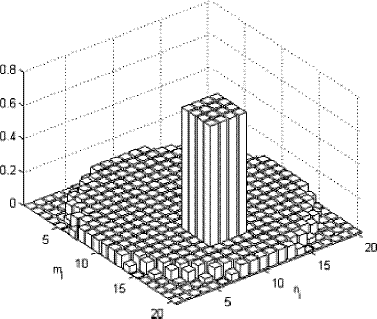
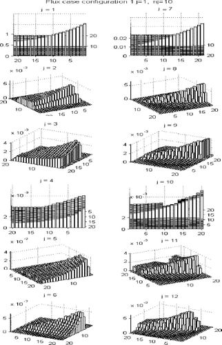
In the first test case configuration shown in both the absorption and scattering coefficients in a embedded rectangular region inside domain D, r = 1, were amplified by a factor of 10, i.e. α1 = β1 = 10. In is shown the solution of the direct radiative transfer problem using the exact values of the radiative properties to show how the radiation propagates inside the medium. Here are considered 2J = 12 sources, and for each source there are 2M = 20 strips. The radiation originated at source j = 1 is coming into the medium only through the strip n1 = 10. Each view corresponds to the components φj, j = 1,2,…,2J. One can easily observe that the scattered radiation is orders of magnitude smaller than the transmitted radiation. Also a careful observer can see the effect of the higher absorption region inside the domain.
FIGURE 8 Solution of the direct radiative transfer problem for configuration 1 with 2J=12 and 2M = 20. Radiation originated at source j = 1 is coming into the medium only through the strip n1 = 10.
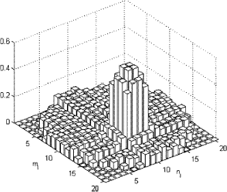
shows the reconstructed values of the radiative properties for test case 1, i.e. configuration 1 with α1 = β1 = 10.
Other test cases were run with configuration 1, varying α1and β1 up to 20, but in for α1 = β1 = 12.5, even though the deviation from the reference values is observed, the reconstruction already becomes significantly degraded.
FIGURE 9 Reconstructed values for the combination of absorption and scattering coefficients. Test case 1 with configuration 1. α1 = β1 = 10.
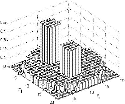
In the second configuration shown in there are two rectangular regions with different properties from domain D. The highest peak represents an amplification by the factor 10 of the absorption coefficient only, and the second peak represents an amplification by the same factor of the scattering coefficient. presents the solution of the direct problem using the exact values of the radiative properties. The same situation described for the results presented in apply here. Now one can easily see the effect of the regions with higher values of the absorption and scattering coefficients. shows the reconstructed values of the radiative properties for the first test case with configuration 2, i.e. r = 2, α1 = 10, β1 = 1, α2 = 1 and β2 = 10.
FIGURE 10 Reconstructed values for the combination of absorption and scattering coefficients. Test case 2 with configuration 1. α1=β1=12.5.
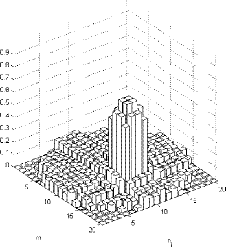
FIGURE 12 Solution of the direct radiative transfer problem for configuration 2 with 2J = 12 and 2M = 20. Radiation originated at source j = 1 is coming into the medium only through the strip n1 = 10.
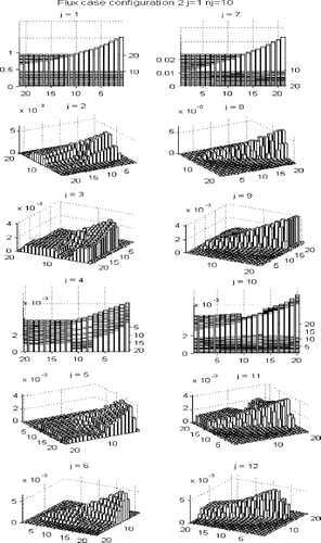
FIGURE 13 Reconstructed values for the combination of absorption and scattering coefficients. Test case 1 with configuration 2. α1 = 10, β1 = 1, α2 = 1, β2 = 10.
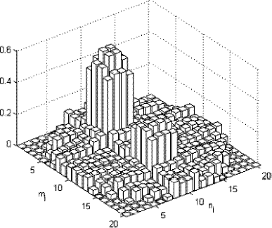
Several other test cases were performed with configuration 2, varying αr and βr, r = 1 or r = 2, independently from 1 to 20. shows the results of the inverse problem for test case 2 with configuration 2 in which α1 = 12.5, β1 = 1, α2 = 1 and β2 = 20.
FIGURE 14 Reconstructed values for the combination of absorption and scattering coefficients. Test case 2 with configuration 2. α1=12.5, β1 = 1, α2 = 1, β2 = 20.
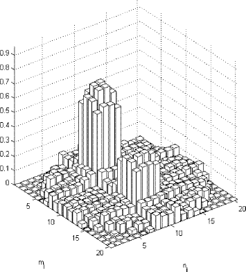
From all test cases performed we conclude that deviations from the reference values of the radiative properties could be detected even in extreme variations of such parameters. Nonetheless for the situations in which scattering increases the peak values of the reconstructed parameters may become significantly smaller than the original ones. This is probably due to the fact that the information on the scattered radiation is not properly taken into account in the inverse methodology developed.
The results presented here were obtained using the logarithmic formulation of the inverse problem given by Eq. (Equation23(--23) ) which has been intensively used for the transmission tomography, but here we consider a discrete ordinates domain partition consistent with the parallel beams of incident external radiation.
We are now working on the full implementation of the inverse radiative transfer problem in which the DITE given by Eq. (Equation22(--22) ) is used for the scattered radiation, and the logarithmic formulation is used for the strip related to the incoming and transmitted radiation.
6. Conclusions
The methodology presented here for the solution of the direct problem of radiation transport in two-dimensional participating media is convenient for the computational implementation of the inverse problem solution for the estimation of a combination of the scattering and absorption coefficients. Therefore, the results previously obtained by Carita Montero et al. [Citation1–Citation3] are a step further generalized with the partial inclusion of scattering. The marches along the spatial coordinate are performed following the directions defined by parallel beams of radiation originated at the external sources. The term of in-scattering is approximated by a quadrature where the quadrature points are determined by the partition of the domain in a way that is consistent with the geometry of the source–detector system, being expected therefore to minimize the errors in the inverse problem solution due to the spatial and angular domains discretization.
With the use of sources and detectors located in different positions (as in the computerized tomography, CT), the discontinuous Galerkin finite element method and the source–detector methodology, we were able to locate defects inside the domain under analysis and to give an estimate for a combination of the absorption and scattering coefficients.
Acknowledgements
The authors acknowledge the financial support provided by CNPq – Conselho Nacional de Desenvolvimento Científico e Tecnológico, FAPERJ – Fundação Carlos Chagas Filho de Amparo à Pesquisa do Estado do Rio de Janeiro, and CAPES – Comissão de Aperfeiçoamento de Pessoal de Nível Superior.
Additional information
Notes on contributors
Antônio J. Silva Neto
†E-mail: [email protected]
*E-mail: [email protected]
Notes
†E-mail: [email protected]
*E-mail: [email protected]
*E-mail: [email protected]
- Carita Montero, RF, Roberty, NC, and Silva Neto, AJ, 2001. Absorption coefficient estimation in heterogeneous media using a domain partition consistent with divergent beams, Inverse Problems in Engineering 9 (2001), pp. 587–617.
- Carita Montero, RF, Roberty, NC, and Silva Neto, AJ, 2000. "Absorption coefficient estimation in two-dimensional participating media using a base constructed with divergent beams". In: Proc 34th National Heat Transfer Conference. Pittsburgh, Pennsylvania, USA. 2000.
- Carita Montero, RF, Roberty, NC, and Silva Neto, AJ, 1999. "Natural base construction for absorption coefficient estimation in heterogeneous participating media with divergent beams". In: Proc. 3rd International Conference on Inverse Problems in Engineering: Theory and Practice. Port Ludlow, Washington, USA. 1999. p. pp. 389–395.
- Kauati, AT, Silva, AJ, and Roberty, NC, 2002. "The source-detector methodology for applications with anisotropic scattering". In: Proc. 4th International Conference on Inverse problems in Engineering: Theory and Practice. Angra dos Reis, Brazil. 2002.
- Kauati, AT, Silva, AJ, and Roberty, NC, 2000. "Use of the source-detector technique in tomography with anisotropic scattering". In: Proc. 17th Brazilian Congress of Biomedical Engineering. Florianópolis, Brazil. 2000. p. pp. 1009–1014, (in Portuguese).
- Arridge, SR, 1999. Optical tomography in medical imaging, Inverse Problems 15 (1999), pp. R41–R93.
- Chandrasekhar, S, 1960. Radiative Transfer, Dover Publications. New York. 1960.
- Kauati, AT, Silva, AJ, and Roberty, NC, 2001. A source-detector methodology for the construction and solution of the one-dimensional inverse transport equation, Inverse Problems in Engineering 9 (2001), pp. 45–66.
- Silva Neto, AJ, and Roberty, NC, 1998. "The source-detector approach for the solution of inverse problems in participating media". In: Proc. 5th N-NE Brazilian Congress of Mechanical Engineering. Fortaleza, Brazil. 1998. p. pp. 340–347, III (in Portuguese).
- Silva Neto, AJ, and Roberty, NC, 1998. "Scattering tomography modelling as an inverse problem". In: Proc. 4th Brazilian National Forum on Science and Technology in Health. Curitiba, Brazil. 1998. p. pp. 317–318, (in Portuguese).
- Özisik, MN, 1973. Radiative Transfer and Interactions with Conduction and Convection, John Wiley and Sons. New York. 1973.
- Duderstadt, JJ, and Martin, WR, 1979. Transport Theory, John Wiley and Sons. New York. 1979.
- Carita Montero, RF, Roberty, NC, and Silva Neto, AJ, 2000. "A method of discrete ordinates consistent with the source-detector system for radiation transport with anisotropic scattering". In: Proc. 3rd Meeting on Computational Modelling. Nova Friburgo, Brazil. 2000. p. pp. 190–191, (in Portuguese).
- Reis, ML, and Roberty, NC, 1992. Maximum entropy algorithms for image reconstruction from projections, Inverse Problems 8 (1992), pp. 623–644.
- Lesaint, P, 1973. Finite element methods for symmetric hyperbolic systems, Num. Math. 21 (1973), pp. 244–255.
- Lesaint, P, and Raviart, PA, 1974. "On a finite element method for solving the neutron transport equation". In: Mathematical Aspects of Finite Elements in Partial Differential Equations, Academic Press. New York. 1974, In: C. de Boor (Ed.).
- Johnson, C, 1987. Numerical Solution of Partial Differential Equations by the Finite Element Method, Cambridge University Press. Cambridge. 1987.
- Silva Neto, AJ, 2002. "Explicit and implicit formulations for inverse radiative transfer problems". In: Proc. 5th World Congress on Computational Mechanics, Mini-Symposium MS 125 – Computational Treatment of Inverse Problems in Mechanics. Vienna, Austria. 2002.
- Carita Montero, RF, Roberty, NC, and Silva Neto, AJ, 2003. "A discrete ordinates strategy for inverse radiative transfer problems in two-dimensional participating media". In: 4th International Conference on Inverse Problems: Identification, Design and Control. Moscow, Russia. 2003.
