Abstract
In this work, metal–mold heat transfer coefficients (h) are determined during unidirectional solidification of Al–Cu and Sn–Pb alloys. The effects of casting assembly (horizontal and vertical), alloy composition, material and thickness of the mold and melt superheat are investigated. By using measured temperatures in both casting and metal, together with numerical solutions of the solidification problem, metal–mold heat transfer coefficients are quantified based on solution of the inverse heat conduction problem. Experimental temperatures are compared with simulations furnished by an explicit finite difference numerical model, and an automatic search selects the best theoretical–experimental fitting from a range of values of metal–mold heat transfer coefficients. Experiments were conducted to analyze the evolution of h during solidification of Al–2, 4.5, 5, 8, 10, 15, 33 wt% Cu alloys and Sn–5, 10, 15, 20, 30, 39 wt% Pb in horizontal and vertical steel chills. The results permitted the establishment of expressions as a power function of time, for different alloy compositions, casting assembly material and thickness of the mold and melt superheat.
Introduction
For the purpose of accurate mathematical modeling of solidification processes, it is essential that correct boundary conditions be established. The heat transfer at the metal–mold interface is one of these boundary conditions, which is of central importance when considering the magnitude of heat transfer during the early stages of solidification. The way heat flows across the casting and the mold surfaces directly affects the evolution of solidification and plays a notable role in determining the freezing conditions within the casting, mainly in foundry systems of high thermal diffusivity like chill casting. Gravity or pressure die casting, continuous casting and squeeze castings are some of the processes where product soundness is more directly affected by heat transfer at the metal–mold interface. The loss of heat when a metal first comes into contact with the mold is regulated not only by the heat storage capacity of the mold material, but also by the heat transfer conditions within the metal itself and particularly at the metal–mold interface. The solid bodies are only in contact at isolated points and the actual area of contact is only a small fraction of the nominal area, as shown in .
FIGURE 1 Heat flow across metal–mold interface and thermal profile in the volume element during solidification (massive mold).

Part of the heat flow follows the paths of actual contact, but the remainder must pass through the gaseous and nongaseous interstitial media between the surface peaks. The interstices are limited in size, so that convection can be neglected. If temperature differences are not extreme, radiation does not play a significant role and most of the energy passes by conduction across the areas of actual physical contact.
The heat flow across a casting–massive mold interface, as shown by the schematic representation of , can be characterized by a macroscopic average metal–mold interfacial heat transfer coefficient (h i ), given by:
FIGURE 2 Thermal resistances and thermal profile in the volume element during solidification (cooled mold).

The interfacial resistance between the casting and the mold surface is generally the largest, and the overall thermal resistance (R g = 1/h g ) is given by:
The present study describes a method for obtaining interfacial heat transfer coefficients as a function of time, from experimental data concerning the solidification of Al–Cu and Sn–Pb alloys in massive and cooled molds. Experimental temperatures in the casting and in the mold are compared with simulations furnished by a numerical model, and an automatic search selects the best fitting from a range of values of interfacial heat transfer coefficients. The effects of alloy composition, material and thickness of the mold and melt superheat are also investigated.
Heat Transfer Coefficient
Several researches have attempted to quantify the transient interfacial heat transfer during solidification in terms of a heat transfer coefficient [Citation1–Citation5]. These studies have highlighted the different factors affecting heat flow across an interface during solidification. These factors include the thermophysical properties of the contacting materials, the casting and mold geometry, the roughness of the mold contacting surface, mold coatings, contact pressure, melt superheat, initial temperature of the mold, etc. The heat transfer coefficient shows a high value in the initial stage of solidification and then decline to a low steady value because the casting contracts from the mold surface, creating an interfacial gap. Most of the methods of calculation of interfacial heat transfer (h) existing in the literature are based on temperature histories at interior points of the casting or mold together with mathematical models of heat transfer during solidification. Among these methods, those based on the solution of the inverse conduction problem have been widely used in the quantification of the transient interfacial heat transfer [Citation6–Citation9].
(A) Inverse Solution
In the present work, a similar procedure determines the values of interfacial heat transfer coefficient by solving the IHCP (Inverse Heat Conduction Problem) by a numerical method. According to Beck, the IHCP is the estimation of the time or spatial profile of surface heat flux given one or more measured temperatures inside a body [Citation6]. Among the variety of proposed methods for solving the IHCP, the iterative gradient technique is a procedure that minimizes a least squares function of the differences between the temperatures measured by thermocouples and temperatures predicted by a direct model of the problem.
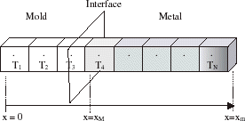
A one-dimensional solidification model of the metal–mold system that predicts the thermal field in a longitudinal section through the system was used to provide a forward problem solution for the inverse problem. This model is based on a previous model developed by Spim, Santos, Quaresma and Garcia [Citation10–Citation12]. A schematic representation of the longitudinal section of the system is shown in .
The inverse problem consists of estimating the boundary heat transfer coefficient at the metal–mold interface from measured mold, water and metal temperatures. The inverse problem can be stated as follows:
| a. | given M measured temperatures T j (j = 1, 2, 3,…, N), | ||||
| b. | estimating the heat transfer coefficient given by its components h i (i = 1, 2, 3,…N). shows a schematic of the stated problem. | ||||
To solve the problem, the estimated temperature computed from the solution of the direct problem using the estimated values of the heat transfer coefficient components h
i
(i = 1, 2, 3,…,N), should match the measured temperatures
as close as possible. This matching can be done by minimizing the standard least squares norm with respect to each of the unknown heat transfer coefficient components.
In the present work, a similar procedure determines the value of h i which minimizes an objective function [Citation10] defined by the equation:
The sequence of the solution involves the calculation of the sensitivity coefficients for measured temperatures. The assumed value of h i is corrected using the relation:
The above indicated procedure is repeated for a new value of h i , and is continued until:
(B) Heat Flow Model [Citation10–Citation12]
The differential equation for heat transfer is known as “General Equation of Heat Conduction in an Unsteady State”, and by considering constant thermal conductivity along heat flux directions and with internal heat generation, it is given for three-dimensional heat flux by:
In this study, a fixed grid methodology is used with a heat source term due to phase change, which is given by an explicit solid fraction–temperature relationship as , where the solid fraction depends on a number of parameters and L is the latent heat of fusion [J/kg]. However, it is quite reasonable to assume that fs varies only with temperature and the fs can be obtained from:
The model permits the insertion of physical properties as a function of temperature, considering the amount of fs, as: k = (k s − k l )·f s + k l ; ρ = (ρ s − ρ1)·f s + ρ l and c = (c s − c l )·f s + c l − (L*df s ), where indices s and l indicate solid and liquid respectively.
Analogy between thermal and electrical systems:
Approximating Eq. (Equation9) by finite-difference terms, and by multiplying heat flux area (At) and Δx, which is equal to the volume, the following is obtained:
The thermal resistance at the heat flux line from point i + 1 or i − 1 to point i is given by:
This term is given by the sum of thermal resistance inside element i (from the centre to the surface) according to the following equations:
This equation can be written as:
Equation (Equation18) or (Equation19) are generic and can be applied to any geometry, by varying only area and volume to be considered.
Experimental Procedure
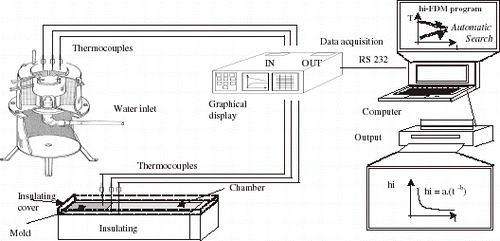
The casting assemblies used in both horizontal and vertical solidification experiments are shown in . Horizontal solidification experiments were performed with Sn, Pb, Al and Al–Cu alloys (4.5; 15; 33 wt% Cu) and Sn–Pb alloys (5; 10; 15 and 39 wt% Pb), including short and long freezing range alloys, as well as eutectic compositions. The casting and chill materials selected for experimentation, and the employed thermophysical properties are summarized in .
TABLE I Casting and chill materials used for experimentation and the corresponding thermophysical properties [Citation12–Citation15]
The main design criteria were to ensure a dominant unidirectional heat flow during solidification. This objective was achieved by adequate insulation of the chill and casting chamber. Copper and low carbon steel chills were used, with the heat-extracting surfaces being polished. In order to investigate the influence of chill thickness on heat flow, five different thicknesses of chills were used (X = 6, 17, 28, 39 and 60 mm). Two chromel–alumel thermocouples were introduced in the chill; one near the chill–casting interface and the other at the outer surface, and a third one was placed in the casting and located at 20 mm from the interface, as indicated in . Each alloy was melted in an electric resistance-type furnace until the molten metal reached a predetermined temperature. It was then stirred until the temperature was brought to a specified value and poured into the casting chamber. The aluminum alloys were degassed with hexachloroethane tablets before pouring. The effect of liquid metal superheat on heat transfer coefficient was also investigated, by using a Sn–10 wt% Pb alloy, a 60 mm thick carbon steel chill and different degrees of superheat: 20, 40, 70 and 100°C above liquidus temperature. The vertical solidification apparatus was designed in such a way that the heat was extracted only through the water-cooled bottom, promoting upward directional solidification. The use of such experimental configuration permits natural convection to be minimized, as well as solute convection due to buoyancy forces if the rejected solute has a higher density than the alloy melt. A stainless steel mold was used having an internal diameter of 50 mm, height 110 mm and a wall thickness of 5 mm. The inner vertical surface was covered with a layer of insulating alumina to minimize radial heat losses, and a top cover made of an insulating material was used to reduce heat losses from the metal–air surface. The bottom part of the mold was closed with a thin (3 mm) disc of carbon steel. The alloys were melted in situ and the lateral electric heaters had their power controlled in order to permit a desired superheat to be achieved. To begin solidification, the electric heaters were disconnected and at the same time the water flow was initiated. Experiments were carried out with Al–Cu alloys (2; 5; 8 and 10 wt% Cu) and Sn–Pb alloys (5, 10, 15, 20 and 30 wt% Pb) at various superheats. Temperatures in the casting were monitored during solidification via the output of a bank of type K thermocouples (1.6 mm diameter) accurately positioned with respect to the heat-extracting surface.
The thermocouples were calibrated at the melting points of aluminum (for Al–Cu alloys) and Tin (for Sn–Pb alloys), exhibiting fluctuations of about 1.0 and 0.4°C respectively. The experimental profiles plotted are the averages of three thermocouples readings at each location in chill and casting. Results from repeated experiments have shown differences not greater than 4°C. All of the thermocouples were connected by coaxial cables to a data logger interfaced with a computer, and the temperature data were acquired automatically. The temperature files were used in a finite-difference heat flow program to estimate the transient heat transfer coefficients.
Results and Discussion
Horizontal Casting
Effect of Alloy Composition
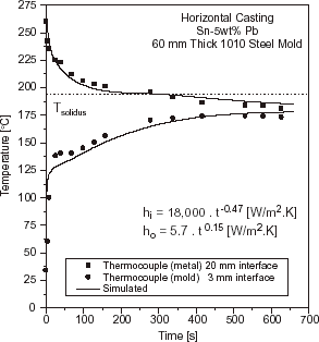
Solidification simulation of each test casting was performed by adopting two different approaches for the liberation of the latent heat of fusion. For eutectic alloys and pure metals, the latent heat (L) was transformed into equivalent number of degrees by considering a temperature accumulation factor (λ) related to L by the specific heat (λ = L/c). For short or long freezing range alloys, the latent heat evolution was taken into account by using Scheil's equation until the remaining liquid reached the eutectic composition. Temperature was experimentally measured in two locations: in the chill at 3 mm from the metal–mold interface and in the casting at 20 mm from this interface. In and typical experimental thermal responses are compared to those numerically simulated by using the transient h i profile which provides the best curve fitting for Al–Cu and Sn–Pb alloys.
FIGURE 6 Experimental and simulated temperatures responses at two locations in casting and chill: 60 mm thick steel chill and a superheat ΔT = 0.1 T L (10% of liquidus temperatures) Al–4.5 wt% Cu.
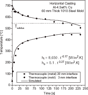
FIGURE 7 Experimental and simulated temperatures responses at two locations in casting and chill: 60 mm thick steel chill and a superheat ΔT = 0.1 T L , Sn–5 wt% Pb.
shows the metal–mold heat transfer coefficients profiles as a function of time for the case of Al–Cu alloys solidifying against a 60 mm thick carbon steel chill.
FIGURE 8 Evolution of the metal–mold interfacial heat transfer coefficients as a function of alloy composition: Al–Cu system, 60 mm thick steel chill and ΔT = 0.1 T L .
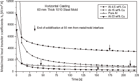
The observed differences in the h i profiles between the pure metals and the other alloys examined can be explained by the total shrinkage accompanying solidification, the extent of the solidification range and the wetting of the mold by the melt. It can be seen that the h i profile increases with increasing mushy zone length. For longer mushy zones, the interdendritic liquid can feed better the solidification contraction causing a continued presence of liquid at the interface, leading to higher values of h i . This can be taken as a general trend, but care should be exercised when applying this conclusion to the early beginning of solidification. As can be seen in , the Al–15 wt% Cu alloy exhibits initial h i values higher than those corresponding to the Al–4.5 wt% Cu alloy, which has a longer mushy zone. At the initial stage of solidification the wetting of the mold by the melt seems to be the dominant factor controlling heat transfer coefficient. In any case a more complex experimental setup would be necessary for an accurate characterization of initial heat transfer coefficients, as fluid flow in the cast alloys, with its associated heat transfer, would be at its strongest.
Effects of Chill Material and Chill Thickness
The effects of chill material and chill thickness on heat transfer coefficient are shown in and , for the cases of a Sn–10 wt% Pb alloy solidifying respectively against a carbon steel and copper chills at a superheat of ΔT = 0.1 T L .
FIGURE 9 Evolution of the metal–mold heat transfer coefficients as a function of chill thickness: Sn–10 wt% Pb alloy, steel chill and ΔT = 0.1 T L .
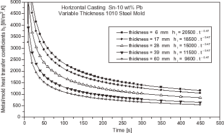
FIGURE 10 Evolution of the metal–mold heat transfer coefficients as a function of chill thickness: Sn–10 wt% Pb alloy, copper chill and ΔT = 0.1 T L .
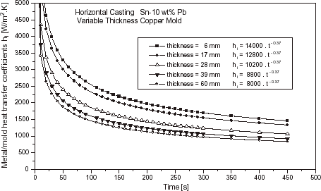
As can be seen by comparing and , the heat transfer coefficient profiles increase with increasing thermal diffusivity of the chill material. These results are in agreement with other studies in the literature [Citation3,Citation7]. It can also be seen that the h i profiles increase with decreasing chill thickness. The chill temperature rises more rapidly from beginning of solidification with decreasing chill thickness. As a consequence, mold expansion favors the thermal contact between metal and chill surface and as the solidified shell is not so thick as for thicker chills, this translates to lower contraction away from the chill. Both factors will contribute to an increase in h i values.
Effect of Superheat
The heat transfer coefficient increases with increasing values of superheat, as can be seen in for a Sn–10 wt% Pb alloy solidifying against a 60 mm thick carbon steel chill. The fluidity of molten alloys increase with increasing superheat, favoring the wetting of the chill by the melt [Citation9,Citation16]. Some results reported in the literature indicate that the surface of solidified shell becomes smoother as the superheat increases for the same chill microgeometry, thus increasing the interfacial contact [Citation17]. Some differences can be observed for values higher than 40°C (). This is not the case for Al, where fluidity plays a more significant role. The initial value of h i rises from about 1500 to 6000 W/m2 K if the superheat is increased from 10% of the melting point (T f ) to 20% of T f [Citation12]. summarizes all the values of h i , expressed as a power function of time, determined during the present experimental investigation for Al–Cu and Sn–Pb alloys under different conditions.
FIGURE 11 Evolution of the metal–mold heat transfer coefficients as a function of superheat: Sn–10 wt% Pb alloy, 60 mm thick steel chill.
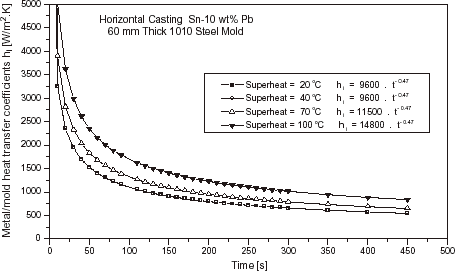
TABLE II Metal/mold heat transfer coefficients during the horizontal directional solidification
Vertical Casting
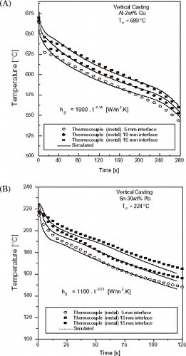
shows typical examples of the evolution of thermal profiles during the course of different experiments of upward directional solidification of an Al–Cu alloy and a Sn–Pb alloy.
FIGURE 12 Typical experimental temperatures responses at three locations in casting: Al–Cu and Sn–Pb alloys (coated mold): (A) Al–2 wt% Cu, (B) Sn–30 wt% Pb.
shows a typical example of the evolution of the overall metal–mold heat transfer coefficient (h g ) during the course of different experiments of upward directional solidification of an Al–5 wt%Cu alloy.
FIGURE 13 Evolution of the overall metal–mold heat transfer coefficient as a function of superheat: Al–5 wt% Cu, water-cooled steel mold.
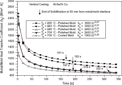
summarizes all the values of h g , expressed as a power function of time, determined during the present experimental investigation for Al–Cu and Sn–Pb alloys under different conditions.
TABLE III Overall heat transfer coefficients during the vertical directional solidification
In can be seen both in and that as expected, under the same condition of melt superheat, the heat transfer coefficient decreases when the mold surface is coated with an insulating layer of alumina. It can also be observed that the increase in melt superheat decreases the heat transfer coefficient. This is, apparently, in contradiction with results obtained in a previous article concerning the horizontal directional solidification of Al–Cu and Sn–Pb alloys [Citation12] and can be explained by the differences on the physical configuration of the two experimental setups. In both cases the superheat delays the solidification evolution. In the horizontal solidification this will translate to a higher h profile for higher melt superheats, since the contraction of metal from the mold wall will also be delayed. In the upward solidification the casting weight will contribute to a better metal–mold thermal contact if lateral contraction is effective (permitting the ingot to be gradually detached from lateral walls). This will happen sooner for solidification without superheat, and as a consequence a higher h profile will be provided with decreasing melt superheat.
Conclusions
From the experimental work on horizontal and vertical directional solidification of Al–Cu and Sn–Pb alloys, the following conclusions can be drawn:
| 1. | for both the horizontal and vertical castings, a rapid drop in interfacial heat transfer coefficient occurs during the initial stages of solidification; | ||||
| 2. | the metal–mold (h i ) or the overall heat transfer coefficient (h g ) can be expressed as a power function of time, of the form h = C 1·(t)− m , where h [W/m2 K], t [s] and C 1 and m are constants, which depend on alloy composition, chill material and superheat. | ||||
| 3. | the transient heat transfer coefficients profiles increase with increasing melt superheat for horizontal directional solidification. A reverse situation has been observed for vertical upward directional solidification, where the h g profiles decrease with increasing melt superheat. | ||||
Nomenclature
Greek Symbols
Subscripts
Acknowledgments
The authors would like to acknowledge financial support provided by FAPESP (The Scientific Research Foundation of the State of São Paulo, Brazil) and CNPq (The Brazilian Research Council).
References
References
- Prates , M and Biloni , H . 1972 . Variables Affecting the nature of chill-zone . Metallurgical Transactions , 3A : 1501
- Ho , K and Pehlke , RD . 1984 . Mechanisms of heat transfer at a metal-mold interface . AFS Transactions , 92 : 587
- Ho , K and Pehlke , RD . 1985 . Metal-mold interfacial heat transfer . Metallurgical Transactions , 16B : 585
- Reddy , AV and Beckermann , C . 1993 . Measurements of metal-mold interfacial heat transfer coefficients during solidification of Sn and Sn–Pb alloys . Experimental Heat Transfer , 6 : 111
- Evans JF Kirkwood DH Beech J 1991 The determination of metal-mold interfacial heat transfer coefficients and the prediction of gross shrinkage cavities in chill mold castings In: M. Rappaz, M.R. Ozgu and K.W. Mahin (Eds.) Modeling of Casting, Welding and Advanced Solidification Processes 531 The Minerals, Metals and Materials Society
- Beck , JV . 1988 . Combined parameter and function estimation in heat transfer with application to contact conductance . Transactions of the ASME , 110 : 1046
- Krishnan , M and Sharma , DGR . 1996 . Determination of the interfacial heat transfer coefficients h in unidirectional heat flow by Beck's nonlinear estimation procedure . International Communications of Heat Mass Transfer , 23 : 203
- Martorano , MA and Capocchi , JDT . 2000 . Heat transfer coefficient at the metal mould interface in the unidirectional solidification of Cu-8% Sn alloys . International Journal of Heat and Mass Transfer , 43 : 2541
- Taha , MA , El-Mahallawy , NA , Assar , AWM and Hammouda , RM . 1992 . Effect of melt superheat and chill material on interfacial heat transfer coefficient in end-chill Al and Al–Cu alloys casting . Journal of Materials Science , 27 : 3467
- Spim , JA and Garcia , A . 2000 . Numerical analysis of solidification of complex shaped bodies: coupling of mesh elements of different geometries . Materials Science & Engineering – A , 277 : 198
- Spim , JA and Garcia , A . 2000 . A modified network approach for modeling solidification of complex shaped domains . Numerical Heat Transfer, Part B – Fundamentals , 38 : 75
- Santos , CA , Quaresma , JMV and Garcia , A . 2001 . Determination of transient interfacial heat transfer coefficients in chill mold castings . Journal of Alloys and Compounds , 319 ( 1–2 ) : 174
- Mondolfo , LF . 1976 . Effect of interfacial energies on heterogeneous nucleation . Materials Science Technology , 5 : 118
- Pehlike RD et al. 1982 Summary of Thermal Properties for Casting Alloys and Mold Materials, University of Michigan
- Toloukian YS et al. 1970 Thermophysical Properties of Matter IFI/Plenum, N.Y. 1
- Kumar , TSP and Prabhu , KN . 1991 . Heat flux transients at the casting/chill interface during solidification of aluminum base alloys . Metallurgical Transactions , 22B : 717
- Flemings MC 1974 Solidification Processing Mc-Graw Hill
