Abstract
A least square dynamically constrained inversion algorithm (DCIA) is developed for monitoring open ocean eddies in the regions, where open boundaries are the major sources of model forecast uncertainties on time scales larger than one week. We employ a finite-difference quasigeostrophic numerical model to constrain evolution of the ocean state. The inversion algorithm is based upon minimization of a quadratic cost function in the space of initial and boundary conditions for quasigeostrophic equations. The problem is regularized by enforcing smoothness in the fields of vorticity, buoyancy, and vertical velocity.
We demonstrate that quasigeostrophic currents in an open ocean 1000 × 1000 km region can be effectively reconstructed using acoustic tomography and satellite altimetry data supported by additional sources of information. Performance of the algorithm is tested in the framework of twin-data experiments and then applied to the real observations. The analyzed observations span over the period of two months and include (i) direct and differential acoustic travel times measured at the array of five acoustic transceivers; (ii) satellite sea surface height measurements; (iii) vertical density profiles, and (iv) current velocities observed by the ship-borne acoustic Doppler current profiler (ADCP). We discuss interpolation properties of the travel time operators, study the impact of various data types on the quality of inversion, and compare performance of the proposed algorithm with the standard least square inversion of the acoustic travel times.
1 Introduction
Acoustic tomography (AT) has always been considered as a prospective tool for monitoring four-dimensional (4d) variability of the ocean. Nevertheless, examples of AT inversions that are useful for quantitative studies are very rare in oceanographic literature. The major reason for that is complexity of the relationship bestween the AT travel times and ocean state variables.
In the past decades methods of oceanographic AT data processing were mostly confined to the least square technique (e.g. [Citation7,Citation25]) and did not take into account prior knowledge of ocean dynamics. With an increase of computer power and advent of the massive satellite observations it became feasible to incorporate complex systems of PDEs into the algorithms of oceanographic data processing. Technically, these algorithms seek for an “optimal” evolution of oceanic fields only among those realizations that obey certain dynamical laws expressed in the form of discrete analogs of PDEs. At present, considerable experience has been accumulated in the inversion of various types of in situ and remotely sensed data using dynamically constrained inversion algorithms (DCIAs) incorporating dynamics of various complexity (e.g. [Citation18,Citation22,Citation24]).
Application of these algorithms to AT inversion problems was initiated by Sheinbaum [Citation17], and Gunson and Malanotte-Rizzoli [Citation6] who considered highly idealized settings of the AT DCIAs within the framework of twin data experiments. Most recently, more realistic twin data AT experimental settings were studied including both sequential [Citation16] and 4d variational inversion schemes involving quasigeostrophic [Citation15,Citation20] and primitive equation [Citation14] constraints.
In the present study we make a step forward in application of the DCIAs to oceanographic data. Six types of observations are synthesized in a dynamically and statistically consistent manner: these include two types of the AT data (direct and reciprocal travel times), satellite altimetry, hydrographic profiles, acoustic Doppler current profiler (ADCP) velocity measurements and wind stress data. 4d data interpolation is performed using a baroclinic quasigeostrophic (QG) numerical model as a strong dynamical constraint [Citation20]. In contrast to previous studies, we treat open boundary conditions of the model as primary control parameters that are varied to obtain an optimal fit of the model trajectory to the data. Additional control fields occupy less than 15% of the control space dimensions and include initial conditions and the wind forcing error field. Our primary interest is to assess feasibility of monitoring mesoscale eddy dynamics in open ocean by means of acoustic tomography complemented by relatively sparse in situ ship-borne observations and satellite altimetry.
The article is organized as follows: in the next section we present a 4d DCIA for synthesis of different types of data. The inversion is based upon finding a least-squares fit of an ocean state to observations, arbitrarily distributed in space and time. The least squares optimization is performed on the nonlinear manifold defined by the QG constraints. Regularization of the problem is introduced by enforcing smoothness of the model fields rather than attracting them to a prior “background state.” This is done to avoid uncertainties associated with the poorly known statistics of the background control fields, especially of those at the open lateral boundaries. Results of twin data experiments are reported in Section 3. They include analysis of the interpolation properties of the travel time operators, the impact of various data types on the quality of inversion, and sensitivity of the results with respect to regularization and observational noise. In Section 4 the algorithm is applied to real data, and its performance is compared with the standard least square inversion of the acoustic travel time observations. Finally, conclusions are given in Section 5.
2 Description of the method
2.1 Dynamical Constraints
We assume that evolution of the 3d ocean state is described by the set of dynamical constraints, that can be derived from the Navier–Stokes equations under the quasigeostrophic approximation (e.g. [Citation13]). Basically, the density deviation ρ from the horizontally homogeneous background state , and the vertical component of the depth-averaged relative vorticity
satisfy the following PDEs:
(--1)
(--2)
here
is the depth-averaged nondivergent horizontal velocity vector,
is the corresponding stream function, subscripts denote partial derivatives,
, overbar stands for the vertical average, H0 is the mean ocean depth, ν is the horizontal diffusivity coefficient, and f is the Coriolis parameter equal to the doubled vertical component of the Earth's angular velocity.
Additional diagnostic constraints are introduced by the relationships between the relative vorticity ω, stream function ψ, vertical velocity w, and density:
(--3)
(--4)
(--5)
(--6)
where g is the acceleration due to gravity, and
is the mean water density. The elliptic equation for vertical velocity is solved with the boundary conditions
(--7)
(--8)
(--9)
where εw(x, y, t) is an unknown error in the estimate of the vertical velocity we(x, y, t) at the base of the Ekman boundary layer, h(x, y) is the depth deviation from H0, and ∂Ω is the lateral boundary of a 3d domain Ω within which the inversion is performed.
The values of g, f, ρ0, ρb, H0, and h are assumed to be known with much greater accuracy than the model's initial and boundary conditions. Therefore, we treat these parameters as known and do not vary them in the course of fitting the model solution to the data. At the time scales considered, the effects of diffusion are negligible, and we fix ν to be small enough to affect only the numerical stability of the solution.
Equations (Equation1(--1) )–(Equation6
(--6) ) require setting the initial conditions for
(Eq. (Equation1
(--1) )), ρ (Eq. (Equation2
(--2) )) and the lateral boundary conditions for ω (Eq. (Equation1
(--1) )), ρ (Eq. (Equation2
(--2) )) and
(Eq. (Equation3
(--3) )). The right hand side of (Equation7
(--7) ) can be estimated on the boundary and does not require additional boundary conditions since
, while Δψ = ω and ψ, ω are known on ∂Ω. Therefore, the problem is entirely controlled by the initial (t = 0) values of the fields
, ρ, the values of ψ, ω (or equivalent values of
) at the lateral boundary and the vertical velocity error εw.
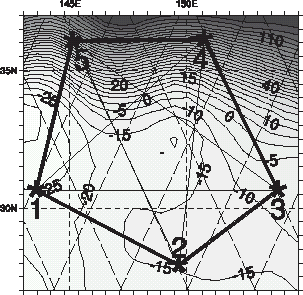
The values of physical parameters uncontrolled by the inversion scheme were chosen to simulate the background conditions in the Kuroshio Extension region, where real acoustic observations have been conducted for 2 months in 1997 [Citation25]. The area is characterized by relatively smooth bottom topography with H0 = 5300 m and h(x, y) not exceeding 550 m. The rest of the model parameters are f = 7.7 × 10⁻⁵ s−1, fy = 1.93 × 10⁻¹¹ s−1 m−1, ρ0 = 1026.5 kg/m3, ν = 500 m2s−1. The model is configured on a rectangular grid with horizontal step δx = 55 km () and variable resolution in the vertical. The vertical grid levels are optimized to minimize the condition number of the vertical differentiation operator present in (Equation4(--4) ). The grid has n = 21 points in each of the three spatial dimensions. In time direction there are nt = 120 intervals, giving T = 60 days of integration with the time step of 12 h. A curious reader can find more details on the employed system of equations and its numerical implementation in the Appendix.
FIGURE 1 Climatological distribution of the seawater density at 236 m in the Kuroshio Extension region. Positions of the acoustic transceivers are given by asterisks and correspond to the configuration of the real AT array maintained in the region for 2 months in 1997. Sloping dashed lines denote satellite tracks along which sea surface height is measured. Solid lines symbolically show the tracks of acoustic rays. Bold lines give the area “best covered” by the acoustic tomography. Density contours are in 10−2 kg/m3.
2.2 Inversion Algorithm
The DCIA is based upon constrained minimization of a quadratic cost function defined on the space of ocean state trajectories Y(t):
(--10)
where the ocean state vector Y at time t is given by the gridpoint values of all the fields present in (Equation1
(--1) )–(Equation6
(--6) ).
and
denote the two groups of terms which attract the model trajectory to the data (
), and regularize the problem (
).
The first group penalizes squared differences between the various data sets and their model counterparts:
(--11)
where the linear operators
, and
project the fields of model sea surface height (SSH) anomalies
![]() and the 3d fields of ρ and stream function ψ onto the measurement points p along satellite tracks and onto the tomographic data respectively.
and the 3d fields of ρ and stream function ψ onto the measurement points p along satellite tracks and onto the tomographic data respectively.
The first two terms in (Equation11(--11) ) correspond to tomographic observations, namely “direct” AT, measuring travel time perturbations δτρ along the ray paths γk, and “differential” AT, measuring the differences of travel times in opposite directions δτψ for a given ray path. Numerically the ray paths were computed by solving eigenray problems [Citation3] for each pair of transceivers in under the assumption of horizontal homogeneity of the background distribution of the inverse speed of sound σb(z). The tomographic operators
and
were computed as second-order approximations to the ray path integrals
![]() which relate travel time perturbations to the variations of the inverse speed of sound σ and along-ray velocities u·s (e.g. [Citation10]). We adopted an empirical linear expression for σ in terms of density perturbations ρ :
which relate travel time perturbations to the variations of the inverse speed of sound σ and along-ray velocities u·s (e.g. [Citation10]). We adopted an empirical linear expression for σ in terms of density perturbations ρ : . The scalar function
was derived from the analysis of long-term hydrographic observations in the region. The grid representation of
was obtained in the form of a n2(n − 1)-dimensional vector, whose elements
satisfy the condition
on the ρ-grid. Similar representation was derived for
.
The last three terms in (Equation11(--11) ) correspond to satellite observations of SSH anomalies, and in situ measurements of density and velocity. Operators
and
linearily project model velocities
and densities onto the corresponding measurement points ennumerated by the indices q and r respectively. The weights
, and Wρ(z) are inversely proportional to the squared error variances of the model/data misfits.
The second group of terms penalizes the amplitude of the Ekman pumping error εw and variability of the density, relative vorticity ω and vertical velocity w fields at spatio-temporal scales close to grid size:
![]() The weights
The weights were computed as inverse squared rms variances of the corresponding fields in the trial (or “first guess”) model run, and then multiplied by the scaling factors, which were tuned to provide an optimal balance between the smoothness of the solution and its statistical consistency with the data. The data were assimilated by varying the initial and boundary conditions of the model in a way that
was minimized. Constrained minimization of (Equation10
(--10) ) was transformed to the unconstrained problem by introducing Lagrangian multipliers (e.g. [Citation8,Citation19]).
Numerically the inverse problem is controlled by the open boundary values of and ρ(∂Ω, t) at two external gridpoint layers, the initial conditions ρ(Ω, 0) and
, and the Ekman pumping error εw(x, y, t). The total number of the gridpoints occupied by the control fields (control space dimension) is D = 435 902. Minimization of the cost function was done iteratively using the M1QN3 quasi-Newton algorithm of Gilbert and Lemarechal [Citation4]. Five diagonals were kept in memory to update the Hessian matrix approximation. The cost function gradient was computed using the adjoint of the dynamical system (Equation1
(--1) )–(Equation9
(--9) ). The inner product (•) in the space of control variables was defined by the diagonal metric
derived from the cost function mean squared gradient
value at the zeroth iteration. Numerically
is represented by the diagonal D × D matrix, whose first n3 = 9181 diagonal elements are the horizontally averaged squared values of the cost function gradient with respect to
and
, which are followed by 43 681 elements representing the mean squared value of the gradient with respect to εw etc. With this metric specification the gradient norm is defined by
![]() so that
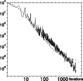
so that at the zeroth iteration. Convergence to the machine precision was achieved, as a rule, after 1000–2500 iterations () depending on the relative magnitude of regularization terms in the cost function.
FIGURE 2 Evolution of the cost function (dashed line) and the norm of the gradient (solid line) with iteration number. Both quantities are normalized by their initial values.
3 Twin data experiments
Four-dimensional interpolation properties of the inversion algorithm were first studied numerically by the “twin data” technique. A reference model trajectory was reconstructed using a limited amount of “data” picked from that trajectory and then contaminated by noise.
3.1 Experimental Setting
The reference model solution was defined by specifying the control vector as follows. Initial conditions for density were generated by adding a number of mesoscale disturbances (upper left panel in ) to the climatological values of ρ (). The barotropic component of the flow at t = 0 was specified by assuming no motion at z = 2000 m. After that the model was integrated for two months with a version of free radiation conditions (e.g. [Citation12]) at the open boundaries and wind stress forcing derived from 6-h NCEP reanalysis for the period of real observations (see Subsection 4.1.2).
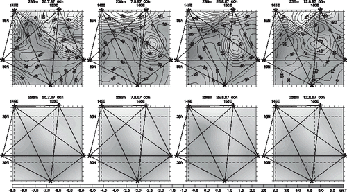
FIGURE 3 Difference between the density fields of the reference and the model solutions at 414 m before (upper panels), and after the inversion. Contour interval is 0.05 kg/m3.
Tomographic and altimetric “data” were then picked from the reference solution using the relationships
![]() where K is the number of ray paths which were kept fixed during the integration period, tildes denote random fields with the amplitudes equal to those of ψ, ρ, and ζ, while ε have the sense of noise levels of the corresponding data. These “data” were used further to reconstruct the reference state.
where K is the number of ray paths which were kept fixed during the integration period, tildes denote random fields with the amplitudes equal to those of ψ, ρ, and ζ, while ε have the sense of noise levels of the corresponding data. These “data” were used further to reconstruct the reference state.
Since the model is nonlinear, the result of inversion may depend on the first-guess solution, which initiates the optimization procedure. In the basic set of experiments we used a “climatological” first-guess solution which was derived in the same manner as the reference solution but without the mesoscale disturbances. Additional experiments were conducted to assess sensitivity of the inversion with respect to variation of the first-guess solution (see Section 3.3). Our basic idea was to find out whether travel time measurements at five acoustic transceivers are sufficient for a robust reconstruction of the smaller scale eddy activity in the region. The quality of reconstruction q was gauged by departure of the optimized model trajectory from the reference one:
(--12)
where ϕ is a state vector component of the model (ψ or ρ), and angular brackets stand for the horizontal average over the pentagonal region in . For simplicity of further treatment we shall characterize assimilated solutions by the parameters
(--13)
which have the meaning of the fraction of the ocean state variance, observed by our measurement system.
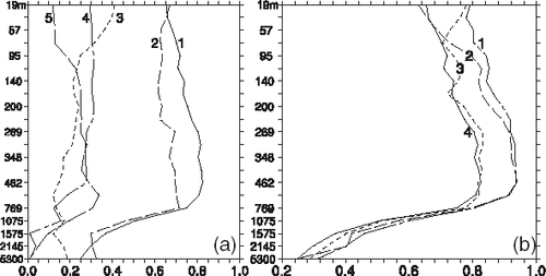
We have conducted more than one hundred DCI experiments to study sensitivity of the algorithm to the structure of ray operators, types of assimilated data, and their noise levels. Typical results are shown in –. As it is seen, more than 70% of the mesoscale signal is captured by AT observations. At the intermediate depths the quality of inversion reaches even higher values (0.8–0.9, b).
FIGURE 4 Quality of inversion q* as a function of the noise level ε for the cases of AT travel time (solid lines) and differential travel time observations. Curves with larger (smaller) q* were computed for the cases of K = 250 (125) rays. SSH noise level εζ = 0.05 was kept constant.
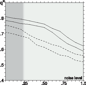
FIGURE 5 Quality of inversion q* as a function of depth for various types of data sets (a) and their combinations; (b) Curves in the left panel correspond to the inversions of travel times δτρ (1); differential travel times δτψ (2); altimetry (3); density
(4); and current velocity
(5); observations. Curves on the right correspond to the inversions of the following combinations of data: δτρ (4); δτρ and δτψ (2); δτρ and
(3); and all types of observations (curve 1). Note that the formal shares of altimetry (3.6%), density (1.0%) and velocity (0.6%) data points in the total amount are much smaller than their relative contributions to the improvement of q*.
3.2 Sensitivity to the Ray Structure
One of the major parameters of an AT observation system is the structure of monitored rays. In the following treatment we assume the ray paths to be fixed and predetermined by the eigenray analysis of the background state σb(z). A more difficult task of establishing the correspondence of the real travel time data with the ray paths (the so-called ray identification problem) will be considered in Section 4.
Each pair of transceivers can be characterized by a limited number of rays whose trajectories depend on the distance between the transceivers and their vertical positions with respect to the main oceanic sound channel located at the depth z of maximum σb (1050 m). A typical ray path oscillates in the vertical around the sound channel axis within a certain sampling depth (SD) range and a horizontal period of 25–50 km. We shall characterize observational properties of a ray system by the Gram matrix
 where
where
![]() and
and are the inverse diagonal elements of
corresponding to the control variable
.
The system would have been perfect if the operators were mutually orthogonal (for instance, each ray would have sampled the ocean at a prescribed depth range that does not intersect with the depth ranges of other rays). A “bad” system is composed of “parallel” operators sampling the ocean along the ray paths which are very close to each other. To characterize the amount of “independent measurements” we introduce the parameter , where gmax is the maximum eigenvalue of G. “Observational efficiency” can be characterized by the ratio
, which gauges the mean contribution of a ray to the total amount of information provided by the system of K rays. η is unity for an “ideal” system and zero for the worst conditioned one. Of course, the above mentioned criterion of “independence” describes the property of observational settings alone and does not take into account the dynamical information. Nevertheless, we assume that M and η can still give us some idea of the ray system properties in the dynamically constrained 4d case.
summarizes the results for the seven ray systems considered. The first 4 lines account for the cases of the maximum possible number of rays (K = 250) and its subsystems (K = 126, 125, and 41). In the first set (K = 126) the total number of rays was reduced two times, whereas the rays with small SDs (oscillating in the vicinity of the sound channel depth z = 1050) were totally omitted. In the second (K = 125) and third (K = 41) subsets the total number of rays was reduced 2 and 6 times, by taking into account only every second (sixth) ray. Three additional experiments were made by varying the vertical position of the transceivers.
TABLE I Assimilation quality  computed for the ray systems with different number of rays K and vertical position h of the transceivers. Superscripts denote data types (travel times TT or differential travel times DT) used in the experiments
As expected, q* has the largest values for K = 250, but this case should not be considered as realistic, because such a large number of rays cannot be identified with confidence at a 1000 km range under typical oceanic conditions [Citation25]. Assimilation quality is weakly sensitive to a double reduction of K (compare lines 1 and 3), and starts to drop as K falls below 80 (8–10 rays per station pair). It is also noteworthy that removal of the rays with small SDs (line 2) degrades observational efficiency of the system and produces larger inversion errors (compare with line 3). Experiments with varying the depths of the transceivers show that for a given number of rays the optimum efficiency and, correspondingly, the best inversion quality is achieved when h coincides with the depth of the sound channel (compare line 3 and lines 5–7).
We conclude that within the framework of the proposed algorithm the ray system can be improved by positioning the transceivers in the main sound channel and taking into the account rays with the smallest possible sampling depth. It should be noted, however, that practical utilization of these rays may appear to be a challenging task because the corresponding acoustic signals are usually more difficult for identification.
3.3 Noise Sensitivity and the Role of Regularization
Results of the inversion experiments conducted for the various values of (ε)ψ, (ε)ρ, and (ε)ζ are shown in . The value (ε) = 0.25 is assumed to be the typical one for oceanic conditions: depending on depth, it corresponds to the noise amplitudes of 5–15 cm/s and to 0.01–0.3 kg/m3 in the fields of velocity and density. For the “observations” of SSH anomalies we took in correspondence with the accuracy of the Topex/Poseidon altimeter. The experiments were conducted for all the ray structures outlined in the previous subsection. The ray patterns corresponding to transceivers' positioning at the axis of the sound channel proved to be the most efficient in the presence of noise as well.
Results in show that the inversion quality is weakly sensitive to the noise level: q* starts to be significantly influenced by noise only at . Even at
the quality of inversion decreases only by 25%. Such a weak dependence of q* on ε can be explained by the integrating nature of AT measurements and the corresponding model-data projection operators
which tend to cancel contributions of the small-scale noise errors in the course of integration along the ray paths.
Another reason for the robustness of the algorithm is the Laplacian-type regularization which heavily penalizes the grid-scale structures in the solution. With a realistic number of monitored rays K ∼ 100 we have approximately 200 observations of direct and reciprocal travel times per model time step, whereas the number of unknown parameters per time step is . Regularization terms introduce a vast amount (∼5 × 10⁶) of bogus data points that can be viewed as “observations of zero Laplacians” of the model fields [Citation19]. These “data” effectively remove noisy solutions from the search subspace and stabilize the problem with respect to noisy variations of the real data and of the first guess state.
The model's nonlinearity may, however, cause multiple minima of corresponding to smooth variations of the first guess control fields. To estimate the degree of non-uniqueness of the inverse solution, we conducted a series of experiments with varying initial and boundary conditions for the first guess solution. Apart from the basic inversion with the “climatological” first guess conditions described in Section 3.1, we tried weaker initial disturbances by multiplying the initial climatological values of ρ and
by the factors
. Inversions were performed with 125 rays (configuration corresponding to line 3 in ). The “degree of nonuniqueness” was gauged by the relative departure d of the vector of optimized control variables C from the same vector obtained at α = 1:
![]()
Results of these experiments are assembled in . As we see, inversions with α ≥ 0.3 are clustered reasonably close to the basic inversion with α = 1. The corresponding quality of inversion lies within the limits obtained with noisy data at noise levels (ε) ≤ 0.5 (). We may thus conclude that inversion uncertainties, associated with multiple minima, are comparable with the uncertainties caused by the observational noise. This result certainly depends on the relative magnitude of regularization weights whose values were optimized to keep d below 0.02 at α ≥ 0.5. With low regularization we failed to obtain inverse solutions at α ≤ 0.3 because of the violation of the CFL condition in the adjoint model during the first few iterations of the minimization procedure. At α ≥ 0.3 the values of d were found to be an order in magnitude larger than those exposed in , whereas the inverse solutions were severely contaminated by the grid-scale noise. Alternatively, with sufficiently high regularization we were able to keep d below 0.001 at α ≥ 0.5, but the quality of inversion degraded to the level of q ∼ 0.2 − 0.3, that is certainly inconsistent with data errors.
TABLE II Results of the inversion experiments with fixed regularization and varying first guess
3.4 Contributions of Differential Tomography, Altimetry and in situ Observations
Impact of the various types of data on the inversion quality was studied by successive introduction of the data subsets into the cost function. Computations were conducted for the case with 125 rays and the spatio-temporal configuration of the data sets outlined in Section 4.
Vertical profiles of q* for various data sets and their combinations are shown in . Tomography data (curves 1, 2 in a) are the most numerous in number among all the data sets. For satellite altimetry, density, and velocity measurements our configuration had 1162, 331, and 180 observation points respectively. Nevertheless, each additional type of observations appears to be important and provides an improvement in q*, which is definitely larger than its formal share in the total amount of measurement points (b).
In particular, sea surface height observations provide major improvement in the uppermost layer of the ocean, which is poorly sampled by the acoustic rays (curve 3 in b). Minor improvements are also seen in the deep layers, indicating better coverage of the barotropic mode in the presence of SSH data. also shows that relative errors are much larger in the deeper layers where their reduction is not as large as in the upper 1000 m of the water column. That can be partly explained by much lower spatial variability of the fields in the deep ocean and their weak dependence on the processes occurring above. Another possible explanation is in the difference in time scales for the upper and lower layers. Effective determination of the 3d ocean structure from the AT data (which are integral by nature) is possible because of the use of data from different times in combination with dynamical constraints which are able to re-distribute information is space–time. However, if time evolution is slow compared to the model integration period, as one would expect for baroclinic modes in deep layers, the system cannot properly determine the 3d ocean structure at those depths, whereas resolution is much better where the ocean changes more rapidly.
4 Assimilation of real observations
4.1 The Data
The core dataset analyzed in the present study was collected in the Kuroshio Extension (KE) region where an array of five acoustic transceiver moorings () was maintained for two months (20.7.97–22.9.97). Yuan et al. [Citation25] gave a detailed account of the data and described some preliminary results obtained by a standard 3d statistical interpolation. Below we will focus on the technical details of the 4d dynamically constrained inversion of the same data and on the comparison with the results of Yuan et al. [Citation25].
4.1.1 Acoustic Travel Times and Ray Identification
In the course of the experiment five acoustic transceivers continuously exchanged the signals measuring acoustic travel times (τ+, τ−) in two opposite directions along the vertical slice connecting a pair of transceivers. Prior to the inversion the values of τ+ and τ− were smoothed in time with a 2-day running mean and then subsampled at 12 h discretization providing the final sets of travel times and differential travel times
.
The most difficult step in preprocessing AT data is identification of the ray paths, i.e. identification of the eigenfunctions corresponding to the measured eigenvalues τk of the ray tracing problem. If the ocean state between a pair of transceivers were perfectly known at any time, the task would be trivial as soon as the ray approximation holds. In real life spatial distribution of the sound slowness σ between transceivers is known within some uncertainty δσ. If δσ is large enough compared to the background distribution σb used for ray tracing, nonlinear effects become significant and may completely destroy the travel time prediction skill of the ray tracing algorithm. Unfortunately, that kind of situation holds for the Kuroshio Extension region where strong variability of the hydrographic fields is always observed and travel time errors associated with nonlinearity may exceed 150–200 ms if a horizontally homogeneous background field σ b(z) is used for ray tracing [Citation21].
We made an attempt to reduce the nonlinearity errors by selecting a horizontally varying background field σb(x, y, z). It was computed by combining in situ observations with the climatological monthly means of Levitus and Boyer [Citation9]. As a result a reasonable fit has been obtained between the computed background travel times and the values of ⟨τk⟩ averaged over the whole period of observations ().
TABLE III Identification of the ray paths. The number of identified rays N is shown for each station pair. The ray bundles are characterized by their temporal mean travel times ⟨τ⟩, the corresponding rms variances , and the rms misfits between the mean measured travel times and those computed using the time-invariant background sound slowness distribution. Error bars show variations of the corresponding quantities within the bundle. Note relatively large travel time variances for the pairs containing stations 4 and 5 located across the KE front (Fig. 1)
We assumed that the observed travel time errors had two basic uncorrelated constituents. The first one, σo = 18 ms is the error associated with inaccuracies in travel time measurements, with the influence of ageostrophic motions, numerical approximations, and with the assumption of a fixed relationship between the modeled density variations ρ and associated variations of the sound speed slowness. The second constituent σk is the error caused by deviations of the real ray paths from the background ones. σk was assumed to depend linearily on a ray's SD [Citation21] and vary from 20 ms for the “low amplitude” rays to 60 ms for the rays probing the entire depth of the ocean. Therefore, absolute values of
varied between 27 and 63 ms.
4.1.2 Satellite Altimetry and in situ Observations
The Topex/Poseidon satellite altimeter crossed the observation region along 12 tracks shown in by dashed lines. SSH anomalies were preprocessed in two steps. First we subtracted the 2-month means from the corresponding along-track data. Then the residual anomalies were low-pass filtered along the tracks and subsampled at 50 km horizontal resolution. We estimate the error σζ of these filtered data ζ* to be 5 cm. This value already incorporates the QG approximation error and has been used for weighting of the T/P observations in the inversion algorithm.
Hydrographic measurements were made along the lines connecting acoustic transceivers during their deployment and recovery cruises. 31 vertical soundings matched the AT observations time frame and were subject to inversion. 17 stations were taken in the first three days along the section, connecting the transceivers 2 and 5 (). The total number of density measurement points was 331. Density observation errors were assumed to be depth-dependent and proportional to the measured rms variations of the density field with the proportionality coefficient ε = 0.25, i.e. a 25% noise level was adopted (cf. Section 3.1). In physical units these errors varied within the range of 0.4–0.05 kg/m3 depending on depth.
Velocities at the AT array were measured simultaneously with the hydrographic surveys by the shipboard ADCP profiler. Assimilated ADCP observations covered the depth interval 185–590 m at 80 m vertical spacing giving the total of 180 data points. 110 velocity values were measured in the first three days of the period of model integration, and the rest 70 observations were taken at the last 2 days. By the analogy with density errors we assume that velocity error σu is proportional to velocity rms variances at different depths with the 25% error level. In physical units σu varied from 0.21 m/s at 110 m to 0.07 m/s at 590 m.
The sixth type of data used in the inversion is the surface wind stress vector converted into the Ekman suction rate we = 1/f curl τ at the base of the upper mixed layer. We used 6-h 10 m winds from the NCEP reanalysis. A nonlinear drag law used by Da Silva et al. [Citation2] was employed to convert wind into stress. When AT observations were made, the spatio-temporal variance of we was close to 4 × 10⁻⁶ m/s. We assumed that the uncertainty σw was equal to 10−6 m/s and did not vary in space and time.
4.2 Comparison with a Standard Inversion
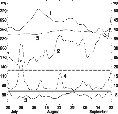
illustrates error reduction in travel times after the inversion. The “first guess” solution corresponding to the upper curves was obtained as a result of model integration with free radiation boundary conditions. This solution is obviously rejected by the AT data. After the inversion the model/data misfits fell well below the prior error bars shown by bold horizontal lines. With rare exceptions (on July 29, and September 22) the QG model fits AT data within one-sigma criterion.
FIGURE 6 Evolution with time of the tomography (solid lines, left axis) and differential tomography (dashed lines, right axis) model/data misfits. Curves 1 and 2 correspond to errors of the first-guess solution. Mean prior error variance levels are shown by thick horizontal lines. Curves 3 and 4 are those obtained after the DCI. Long dashed line 5 (left axis) shows evolution of the travel time error obtained by the LSI method.
Yuan et al. [Citation25] processed the same travel time data without employing the dynamical constraints. In their inversion (hereafter LSI) the sound slowness field was represented by 100 basis functions, which did not vary in time. The travel time data were inverted by the least square optimization of the amplitudes of the basis functions at every time step independently.
When compared with a result of LSI (curve 5 in ), the corresponding DCI error (curve 3) exhibits a somewhat stronger variation in time caused by imposing additional dynamical constraints. The average travel time error is, however, almost five times smaller for the DCI analysis. This can be explained by at least two reasons: (i) a larger number degrees of freedom per time step used in the present study; and (ii) ability of the DCIA to do interpolation with spatially varying resolution.
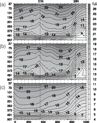
Advantages of the DCI approach are also seen in , which gives a comparison with direct observations of the reconstructed temperature sections in the vertical plane connecting transceivers 2–5 (). The DCIA has captured the mesoscale disturbance at 31°N with a pronounced cold core above 300 m whose anomaly changes in sign below that level. This structure is also seen in the optimal initial conditions in the case when hydrographic data are not taken into the account (see also [Citation21] for comparison of the linear and nonlinear 3d inversions of the same travel time data).
FIGURE 7 Temperature section along (T2–T5) line as measured on July 20–22 by CTD hydrocasts (a) and obtained as a result of the DCI (b), and LSI (c) methods.
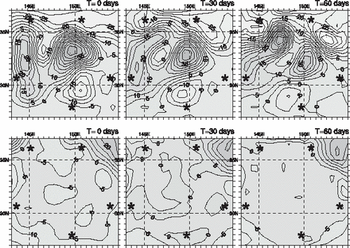
Temporal variability of the temperature anomalies at 200 m is compared in . The results of LSI and DCI are in qualitative agreement. Both reproduce the cold meander (CM) at 150–152°E and 32–33°N and trace the average location of the KE front at 35°N. Dynamics of the warmer waters south of KE front appear to be different primarily because of the missing cold disturbance at 31°N 148°E in the lower panels. Horizontal structure of the CM also seems to be different. Our inversion interprets it as a detached mesoscale eddy which was moving westward at a speed of 4 cm/s in July–September and eventually decayed at the end of the measurement period (, upper panels). LSI interprets CM as a semi-detached quasistationary disturbance whose amplitude decreased in mid-September simultaneously with the southern retreat of a large warm disturbance which has developed at 147°E 34°N by the end of August. On the upper panels in an intense warm anomaly also reaches the latitude of 35° at the end of August, but its maximum meridional extension is observed almost 2.5° east of the analogous feature seen in the lower panels in . Dynamics of that warm anomaly was characterized by strong interaction with the CM eddy, resulting in the detachment of a warm core eddy which is clearly seen in the second half of September at 34°N 151°E in both temperature and stream function fields. Detachment of the eddy from the western warm water tongue was possibly triggered by a cold core anomaly at 31–32°N, 147°E, which has not been captured by the LSI.
FIGURE 8 Comparison of the evolution of temperature anomalies (gray color) inferred from the dynamically constrained inversion (upper panels) with the anomalies obtained by the 3D LSI method of the same travel time data. Stream function is available only for the DCI solution and is shown by contours (in 1000 m2/s).
We assume that significant discrepancies in the positions and evolution of mesoscale features arise due to the absence of dynamical constraints in the LSI approach. As can be observed in the lower panels of , a large portion of temporal variability in temperature anomalies is spatially confined to the points of ray intersections. In the 4d variational approach, such a “restricted” mode of variation is not consistent with QG dynamics, and time evolution of the mesoscale features appears to be more realistic. Quantitatively, the results of DCI provide a much better fit to the travel times () and demonstrate statistical consistency with the additional five types of data which are not taken into the account by the LSI method.
5 Summary
We have illustrated a possibility to employ AT data for reconstruction of the oceanic variability using quasigeostrophic dynamical constraints in combination with other types of observations, which are linearily related to the ocean state vector. AT observations are obviously the most difficult component to handle, since the exact operators, projecting oceanic state variables onto the travel times are nonlinear, especially in the energetic regions like Kuroshio Extension. We have managed to find a reasonable solution to the problem by considering horizontally inhomogeneous reference state and taking into account errors associated with the above mentioned nonlinearity and finite accuracy of the algorithm projecting model variables onto the ray paths. The proposed DCIA has shown good performance and was found to be superior to the standard least squares inversion in terms of the formal model/data misfits and from the viewpoint of flexibility in the description of mesoscale structures. Therefore, we assume that the major goal of investigation has been successfully achieved.
Because of the large dimension of the problem, carrying out rigorous sensitivity analysis and posterior error estimation was prohibitive from the computational point of view. We do believe, however, that experiments described in Section 3 shed some light on the statistical properties of the DCIA, demonstrate its well-posedness and also the robustness of the inverse solutions.
Employment of the Tikhonov-type weak smoothness constraints is an important feature of the presented algorithm. This choice of regularization resulted in somewhat slower convergence than one may expect from regularization based upon attracting the control variables to some pre-determined “background” values. However, our formulation of the problem appears to be computationally feasible for moderate facilities. It is also free from uncertainties associated with the necessity to choose the background state and its covariance at the open lateral boundaries. Preliminary numerical experiments have shown much better performance of the smoothness regularization technique when a 2-month assimilation period was considered.
Experiments with varying the positions of acoustic transceivers in the vertical have shown that the best observability is achieved when the travel time measurements are performed at the axis of the main sound channel. For a given number of rays observational properties of the AT system are optimal when the rays are evenly distributed over the sampling depth spectrum and small amplitude rays are taken into the account. The data components considered in this study complement each other in three aspects: travel time data provide information on the baroclinic structure of the ocean, differential travel times contain a considerable barotropic signal while altimetry provides additional description of the upper layer, poorly observed by the ray patterns. Observations of the upper layer densities and velocities, although limited in number, significantly improve the quality of inversion by correcting the errors caused by a limited accuracy of the travel time operators.
In a broader context, the described DCI technique can be applied for acoustic monitoring of hydrodynamic flows with weak perturbations of the background sound speed distribution, i.e. when the ray paths' variations are negligible. Dynamical constraints employed in this study are substantially nonlinear and close in complexity to the general Navier–Stokes equations in 2d. We have shown feasibility of the travel time inversion for control space of a large (∼5 × 10⁵) dimension with Tikhonov-type smoothness regularization and unknown boundary conditions. In application problems with well-known boundary conditions, the control space may include diffusion coefficient varying in space and time and/or other important characteristics of the monitored medium.
Despite a promising performance of the presented algorithm, there are still a lot of problems with AT data inversion. The central one is adequate representation of the ray operators in media with strongly varying sound speed. Employment of a horizontally inhomogeneous background state is just a partial solution to the problem obtained at the expense of a significant increase of the prior error bars for AT data. For longer integrations and larger separations between transceivers nonlinearity of the ray operators may substantially contaminate the linearily processed signal. Taking second-order corrections to travel times is computationally expensive and may have limited applicability, because quadratic approximation still implies that the rays are close to their reference paths. An alternative way is to update the ray paths after a certain number of iterations of the optimization procedure. With this approach it is necessary to estimate the effect of the errors associated with interpolation from the model grid onto the updated ray paths which usually have extra-fine (200–500 m) horizontal resolution. Other important issues like processing of the acoustic travel time data by means of the open boundary controlled numerical models based on 3d Navier–Stokes equations are still at the very beginning of their investigation.
Acknowledgments
The major part of the article was presented as an invited talk at the First International Symposium “Inverse Problems: Modeling and Simulation” [Citation23]. The study was supported by NASA Grant NAG5-10045, NOAA Grant NA17RJ 1230 (to JIMAR), and the Frontier Research system for Global Change through its sponsorship of the International Pacific Research center (IPRC). SOEST contribution number 6254. IPRC contribution number 233.
Additional information
Notes on contributors
Dmitri Nechaev ‡
‡E-mail: [email protected]
†E-mail: [email protected]
Notes
‡E-mail: [email protected]
†E-mail: [email protected]
†E-mail: [email protected]
- Arakawa, A, 1966. Computational design for long-term numerical integration of the equations of fluid motion: two-dimensional incompressible flow, Part I, J. Comput. Phys. 1 (1966), p. 119.
- Da Silva, AM, Young, CC, and Levitus, S, 1994. Atlas of surface marine data, Algorithms and Procedures 1 (1994), NOAA/NODC.
- Dushaw, BD, and Colosi, JA, 1998. "Ray tracing for ocean acoustic tomography". In: APL University of Washington Tech. Report TM 3–98. 1998. p. 31pp.
- Gilbert, JC, and C. Lemaréchal, , 1989. Some numerical experiments with variable storage quasi-Newton algorithms, Math. Program. 45 (1989), p. 407.
- Griffies, SM, Böning, C, Bryan, FO, Chassignet, EP, Gerdes, R, Hasumi, H, Hirst, A, Treguier, A-M, and Webb, D, 2000. Developments in ocean climate modelling, Ocean Modelling 2 (2000), p. 123.
- Gunson, JR, and Malanotte-Rizzoli, P, 1996. Assimilation studies of the open ocean flows. 1. Estimation of initial and boundary conditions, J. Geophys. Res. 101 (28) (1996), p. 457.
- Howe, BM, Worceter, PF, and Spindel, RC, 1987. Ocean acoustic tomography: mesoscale velocity, J. Geophys. Res. 92 (1987), p. 3785.
- Le Dimet, FX, and Talagrand, O, 1986. Variational algorithms for analysis and assimilation of meteorological observations: theoretical aspects, Tellus 38a (1986), p. 97.
- Levitus, S, and Boyer, TP, 1994. World Ocean Atlas 1994 Vol. 3, 4 (1994), NOAA Atlas NESDIS 3, 4. US Dept. of Commer., Washington, D.C.
- Munk, W, Worcester, P, and Wunsch, C, 1995. Ocean Acoustic Tomography. New York. 1995. p. pp. 434.
- Nechaev, D, and Yaremchuk, M, 1994. CTD data assimilation into a three-dimensional quasigeostrophic open ocean model, Dyn. Atmosph. and Oceans 21 (1994), p. 137.
- Orlanski, I, 1976. A simple boundary condition for unbounded hyperbolic flows, J. Comput. Phys. 21 (1976), p. 251.
- Pedlosky, J, 1987. Geophysical Fluid Dynamics. New York. 1987. p. 710pp, 2nd Edn..
- Remy, E, and Gaillard, F, 1999. "Assimilation of simulated acoustic tomography data". In: Proc. WMO Symp. on Assimilation of Observations in Meteorology and Oceanography. Quebec City, Canada. 1999, 7–11 June.
- Remy, E, Gaillard, F, and Verron, J, 2002. Variational assimilation of ocean tomographic data: twin experiments in a quasi-geostrophic model, Q. J. Roy. Meteor. Soc. 128 (2002), p. 1739.
- Shinke, T, Yoshikawa, Y, Kamoshida, T, and Mitsudera, H, 2001. Analysis method for ocean acoustic tomography data using Kalman filter: evaluation by identical twin experiment, Japanese Journal of Applied Physics 40 (2001), p. 3835.
- Sheinbaum, J, 1995. Variational assimilation of simulated acoustic tomography data and point observations: a comparative study, J. Geophys. Res. 100 (1995), p. C10, 20, 745.
- Thacker, WC, and Long, RB, 1988. Fitting dynamics to data, J. Geophys. Res. 93 (1988), p. 1227.
- Thacker, WC, 1988. Fitting models to inadequate data by enforcing spatial and temporal smoothness, J. Geophys. Res. 93 (1988), p. 10 556.
- Yaremchuk, M, and Nechaev, D, 2001. Simulations of quasigeostrophic currents derived from satellite altimetry and acoustic tomography of an open ocean region, J. Atmosph. Oceanic Tech. 18 (11) (2001), p. p. 1894.
- Yaremchuk, M, and Yaremchuk, A, 2001. Variational inversion of the ocean acoustic tomography data using quadratic approximation to travel times, Geophys. Res. Lett. 28 (9) (2001), p. 1767.
- Yaremchuk, M, and Lebedev, K, 2002. Inverse modeling of intra-annual variability in the subtropical North Pacific, J. of Phys. Oceanogr. 32 (10) (2002), p. 2 725.
- Yaremchuk, M, and Lebedev, K, 2002. "A 4-dimensional inversion of the acoustic tomography and satellite altimetry data using quasigeostrophic constraints". In: Proc. 1st Int. Symp. Inverse problems: Modeling and Simulation. Turkey. 2002. p. p. 174.
- Yu, L, and Malanotte-Rizzoli, P, 1998. Inverse modeling of the seasonal variability in the North Atlantic Ocean, J. Phys. Oceanogr. 28 (1998), p. 902.
- Yuan, G, Nakano, I, Fujimori, H, Nakamura, T, Kamoshida, T, and Kaya, A, 1999. Tomographic measurements of the Kuroshio extension meander and associated eddies, Geophys. Res. Lett. 26 (1999), p. 79.
Appendix
The equations of quasigeostrophic (QG) approximation (e.g. [Citation13]) are widely used in geophysical fluid dynamics to describe oceanic variability at time scales exceeding 1–2 days and spatial scales L larger than 10–20 km. At these scales ocean currents have a typical magnitude U ∼ 10–30 cm/s, the Rossby number is small, and the Coriolis force is almost balanced by the horizontal gradient of pressure p:
Conventionally QG equations are written in the local Cartesian coordinates with x directed eastward, y northward, and z upward. The Earth's curvature is neglected, since the spatial scale of study region is much smaller than the Earth's radius. The horizontal variations of the Coriolis parameter
are small in such regions, and QG velocity field is nondivergent with scaled p playing the role of the stream function
. Here ωE is the vertical component of the Earth's angular velocity.
In addition to the geostrophic relation (A1), QG approximation includes vorticity evolution equation, buoyancy (entropy) conservation equation, and the hydrostatic relation:
where ω = Δψ. Equations (A2) and (A3) can be reduced to a single conservation equation for the QG potential vorticity. The latter equation is derived from Eqs. (A2) and (A3) as (A2)
(A3)] (bracketed numbers symbolically denote the corresponding equations).
In this study we utilize the system of Eqs. (Equation1(--1) )–(Equation9
(--9) ) which is equivalent to the conventional equations of QG approximation. Equation (Equation1
(--1) ) is obtained by vertical averaging of (A2):
Relationships (Equation3
(--3) ), (Equation5
(--5) ), and (Equation6
(--6) ) can be easily derived from the geostrophic balance (A1), the definition of ψ, and hydrostatics (A4). Equation (Equation4
(--4) ) is obtained as
and taking (Equation5
(--5) ) and (Equation6
(--6) ) into the account.
The system (Equation1(--1) )–(Equation9
(--9) ) has been already used in [Citation11,Citation20], for 4d dynamically constrained inversions of oceanographic data. Our specific choice of variables (
instead of potential vorticity and stream function) was made for two reasons. First, the state vector contains density perturbations instead of the hardly measurable potential vorticity. This requires less complicated model-data projection operators, resulting in a better conditioning of the inverse formulation of the model. Second, the diagnosed model fields include vertical velocity which may be important in applications.
The model fields are discretized on Arakawa's A-grid (e.g. [Citation5]) with homogeneous horizontal stepping δx = δy and variable spacing δzk in the vertical. Central differences in space and time are used to approximate the first-order differential operators. The Laplacian Δ and ∂zz are represented by
 The operator J is approximated by the standard Arakawa's scheme [Citation1]. The discrete representation
 of the vertical average in (A5) is given by the standard trapezoidal rule:
![]() Under this notation the finite-difference scheme for the Eqs. (Equation1
Under this notation the finite-difference scheme for the Eqs. (Equation1(--1) )–(Equation6
(--6) ) can be written down in the form
where for simplicity we omitted the indices {i, j, k, m} which enumerate the elements of the arrays representing model variables. The system (A6)–(A11) is integrated forward in time using the leap-frog scheme. The integration algorithm provides a nonlinear mapping of the 435 902-dimensional control vector C of the initial and boundary grid point values of the appropriate fields onto the 4d model state
.
The cost function is minimized with respect to the components of C subject to the constraints given by (A6)–(A11). We utilize the standard constrained minimization technique (e.g. [Citation8]) and introduce the Lagrangian function:
where λs represent the values of the Lagrangian multipliers at a grid point ijkm, and bracketed numbers symbolically denote the finite-difference relationships (A6)–(A11) written down at the same point. Given a set of control variables C, we solve the system
by integrating (A6)–(A11) forward in time, and simultaneously compute the cost function value
. The adjoint system
is derived analytically from (A12), and then solved by backward integration in time to provide the cost function gradient
with respect to C. Given the algorithm
, we utilize the quasi-Newton minimization algorithm of Gilbert and Lemaréchal [Citation4] to perform the minimization.